 Arduino Enigma
This project documents how to turn a web page into a functioning physical object. It has a hardware and a software side.
The software side of this project is a port to the Arduino platform of the original Sinclair Scientific Calculator simulator (http://righto.com/sinclair).
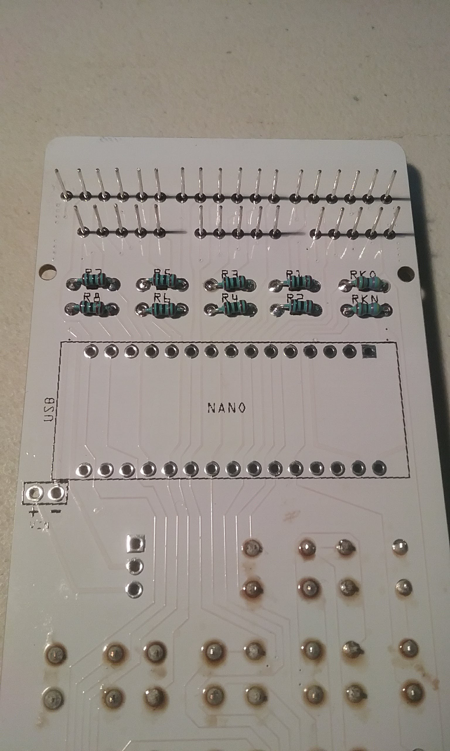
The hardware part has evolved over time. It started as a quick modification to the Kim UNO by @Oscarv (http://obsolescence.wixsite.com/obsolescence/kim-uno-summary-c1uuh) with the keys arranged in the Sinclair pattern and a 9 digit display.
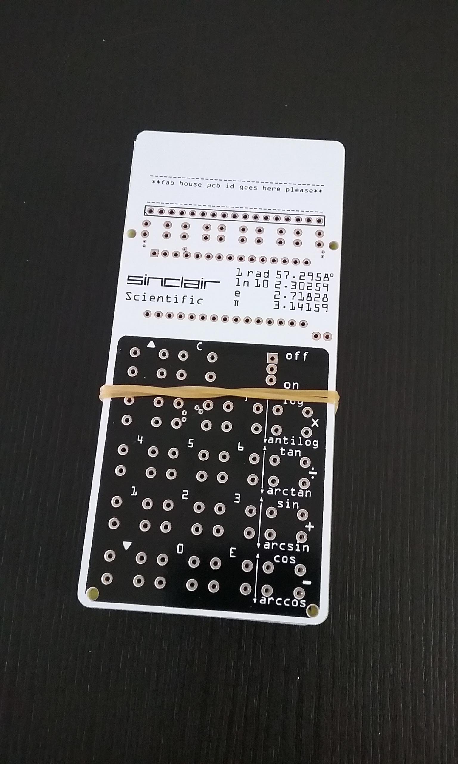
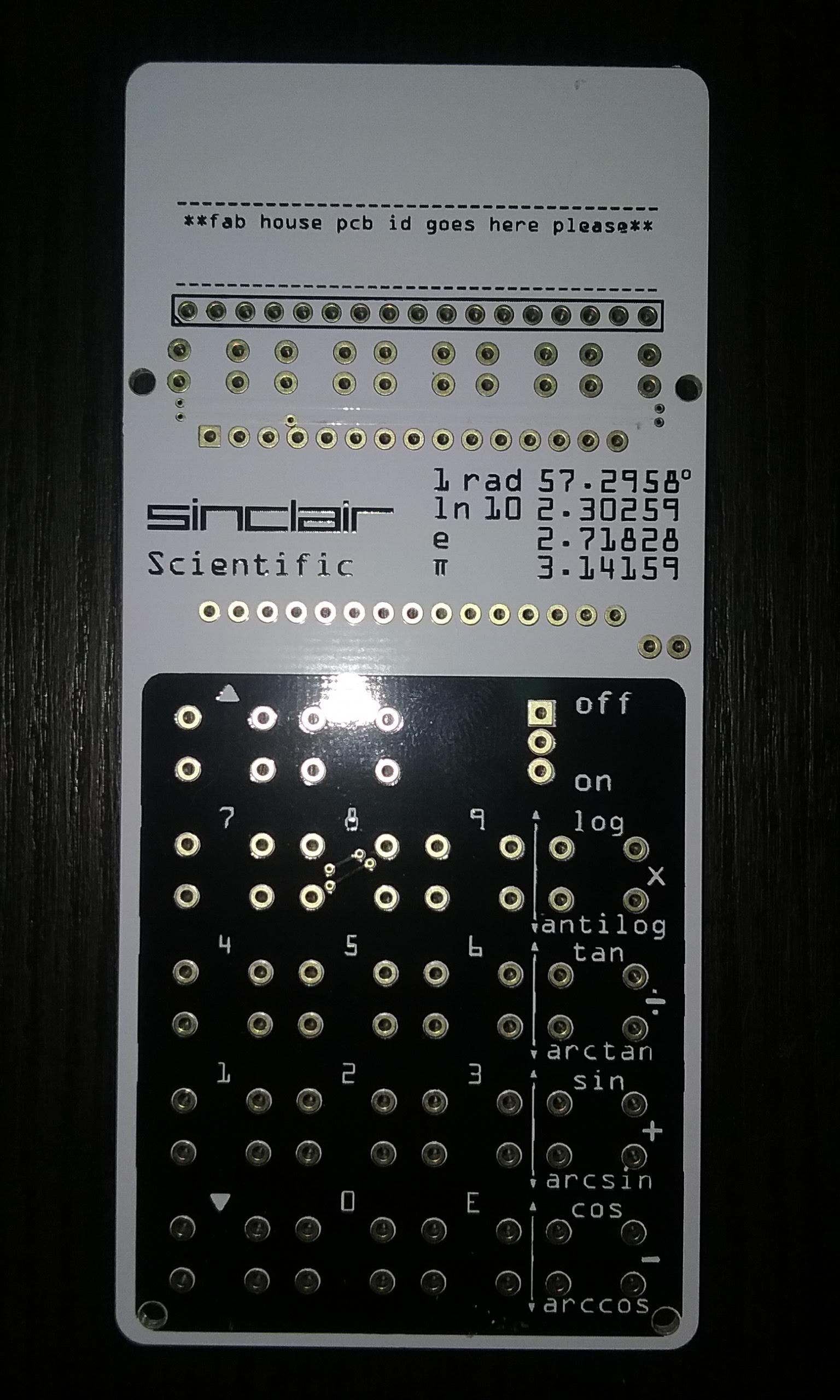
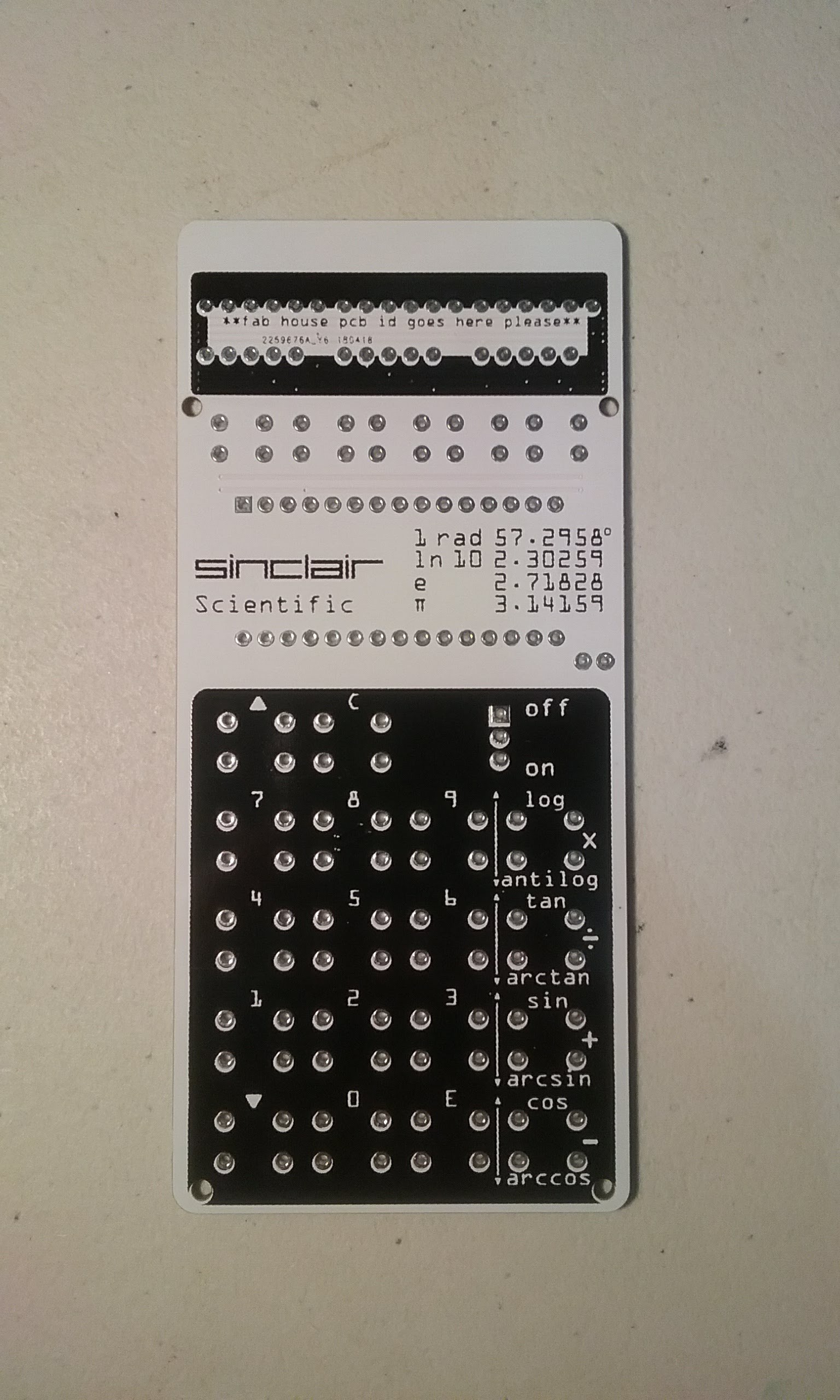
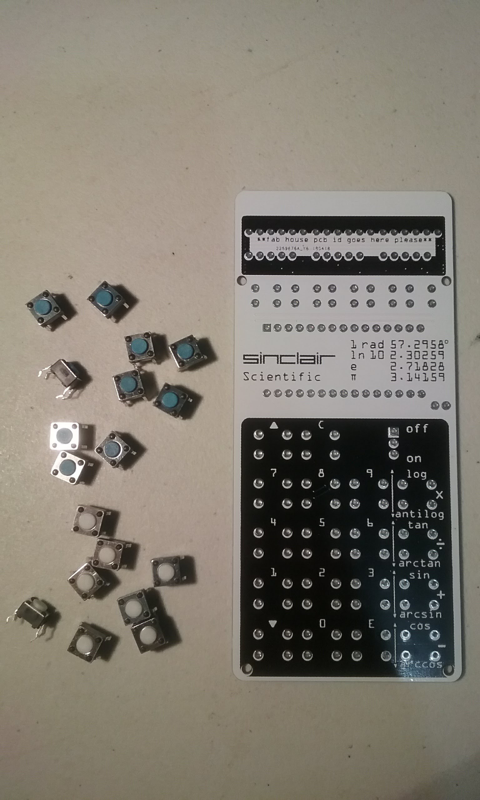
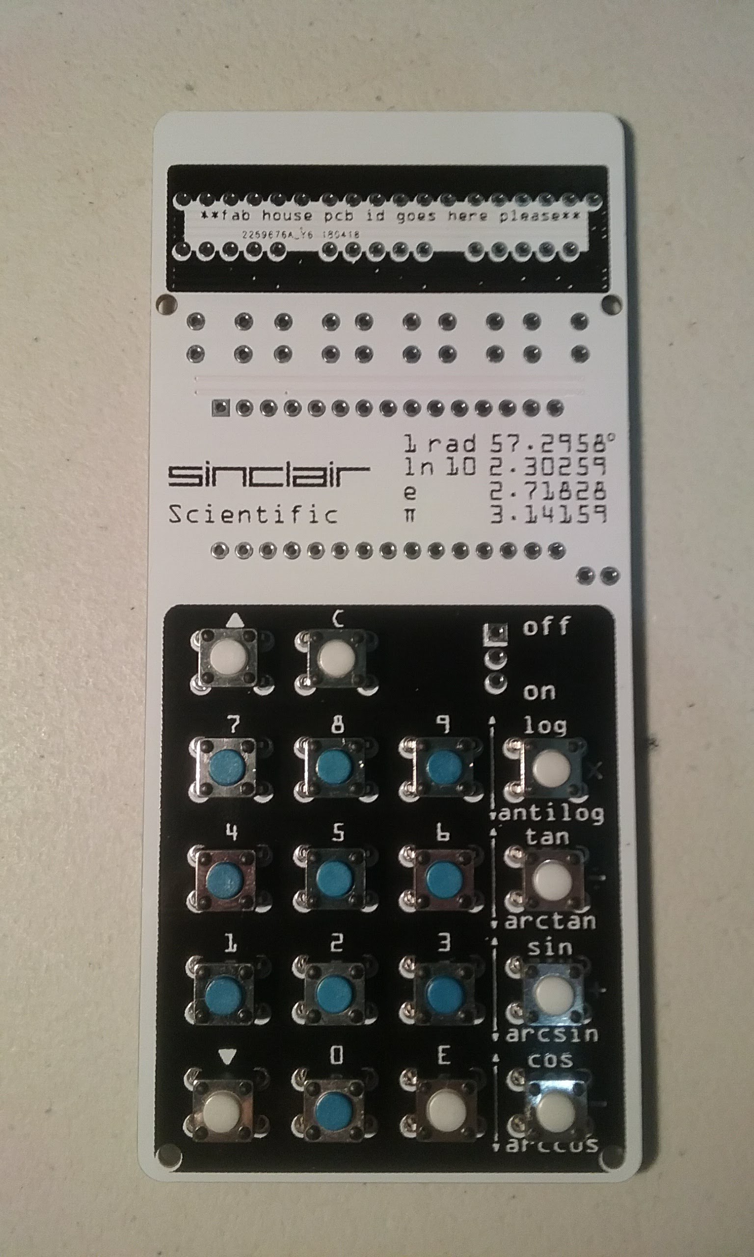
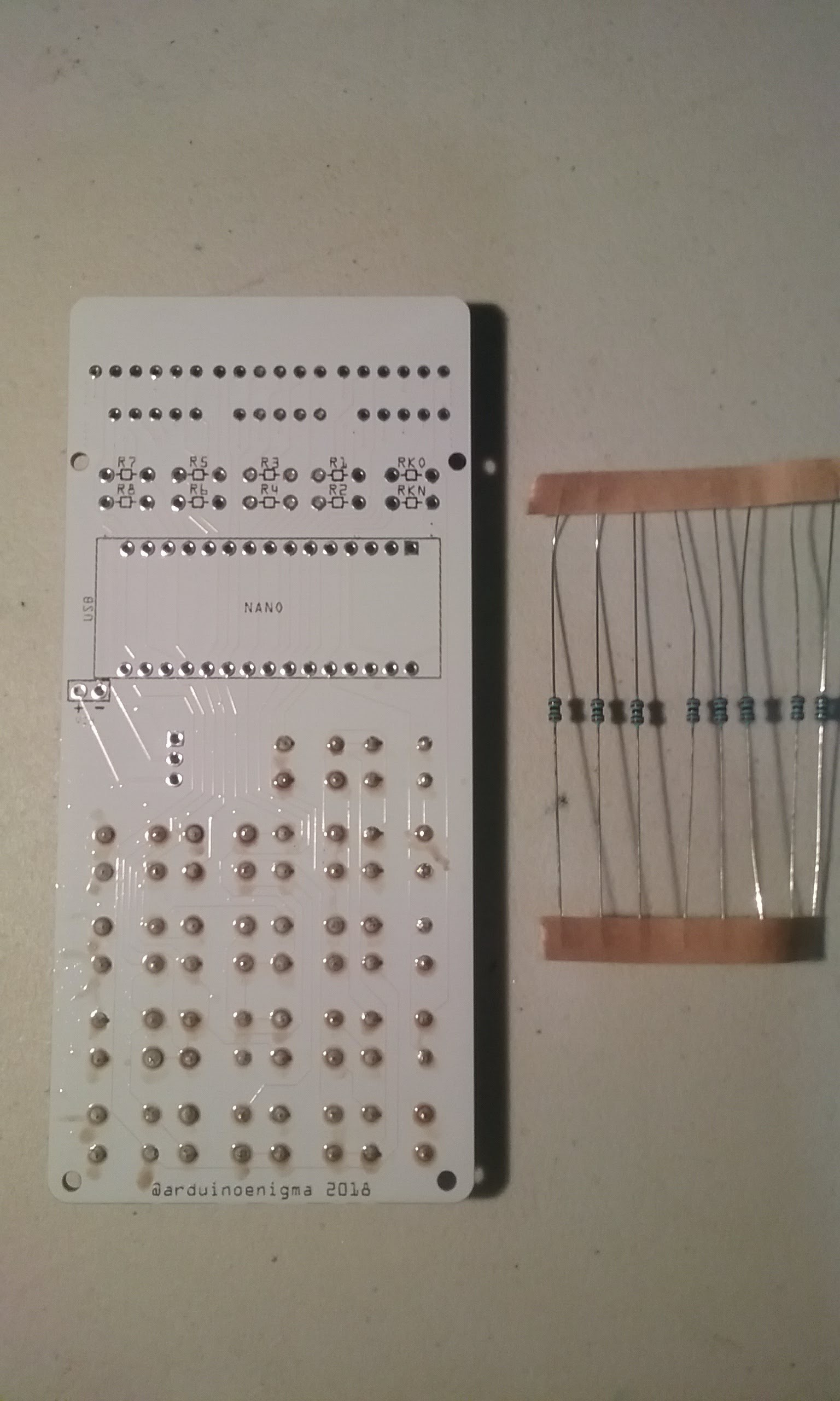
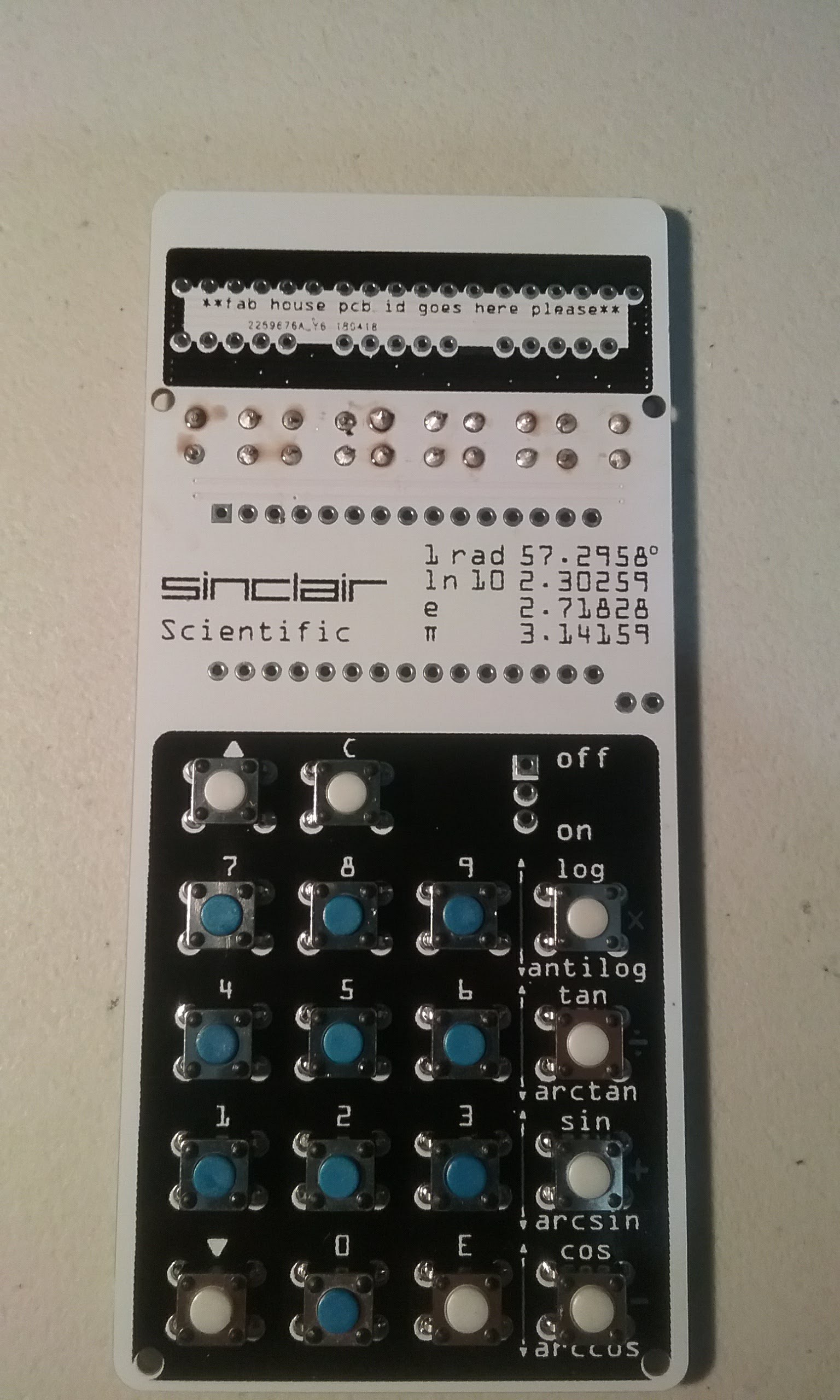
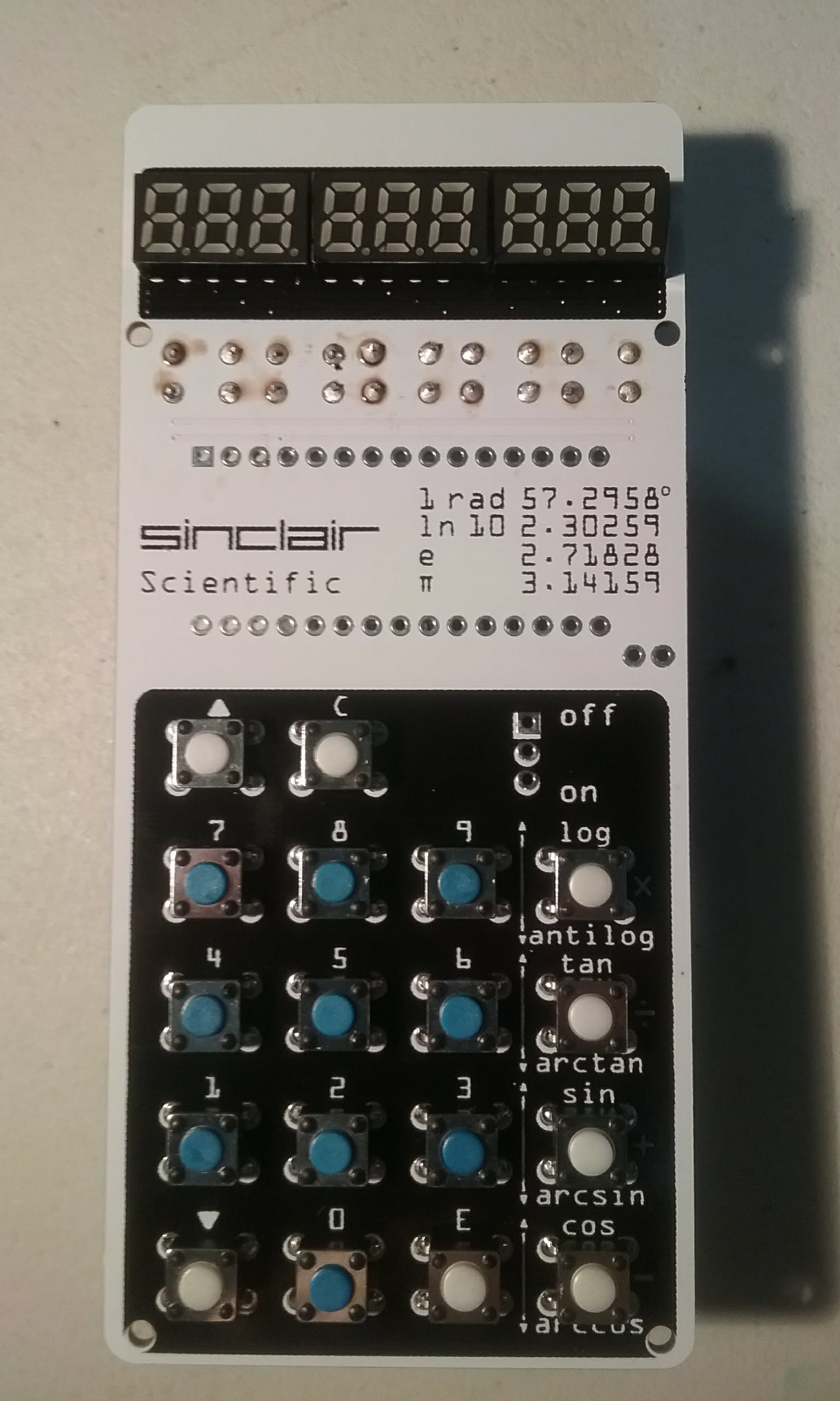
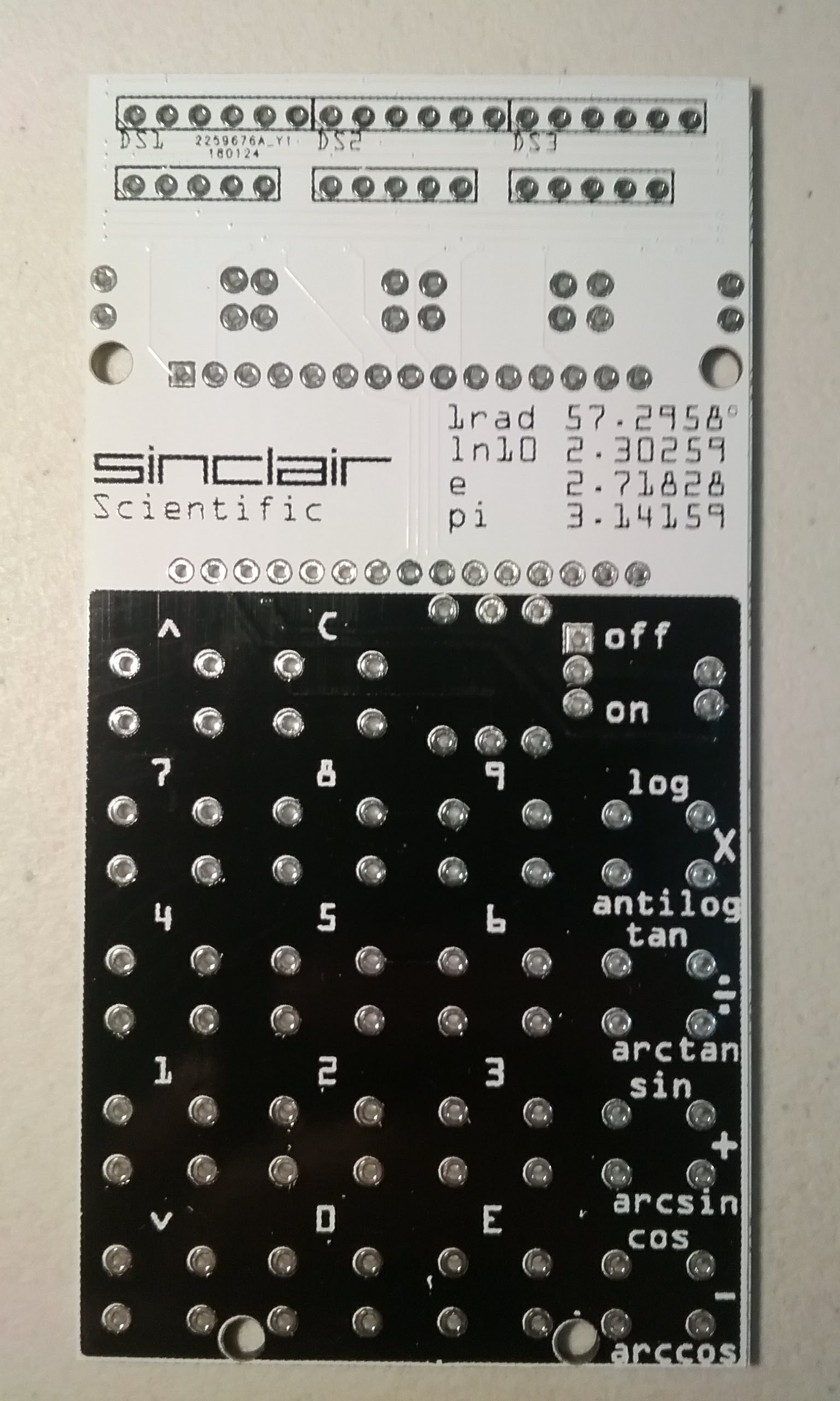
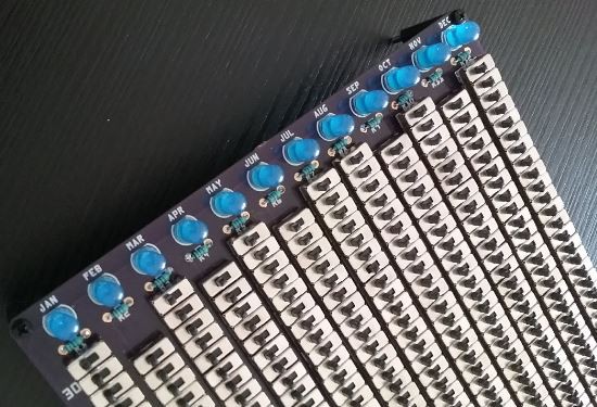
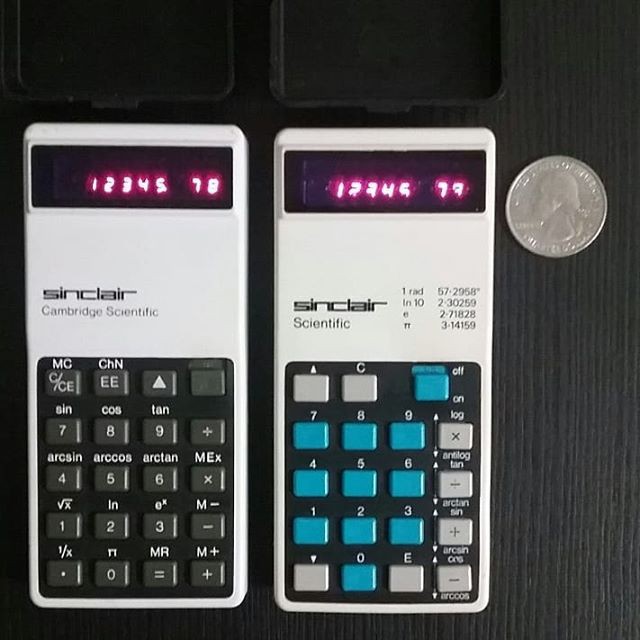
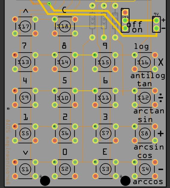
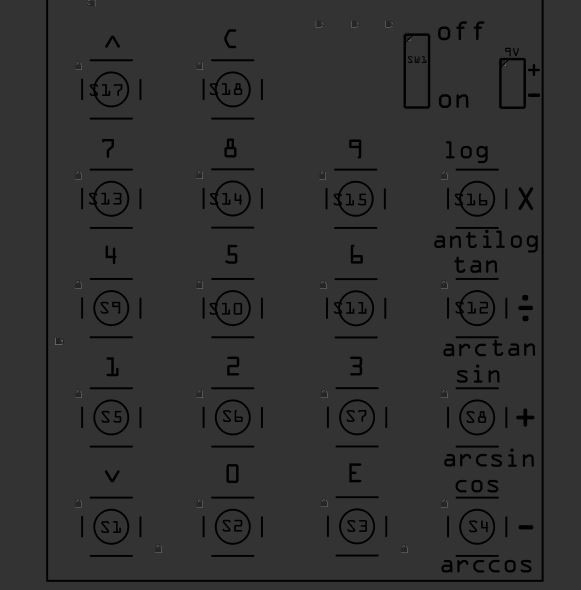
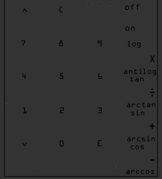
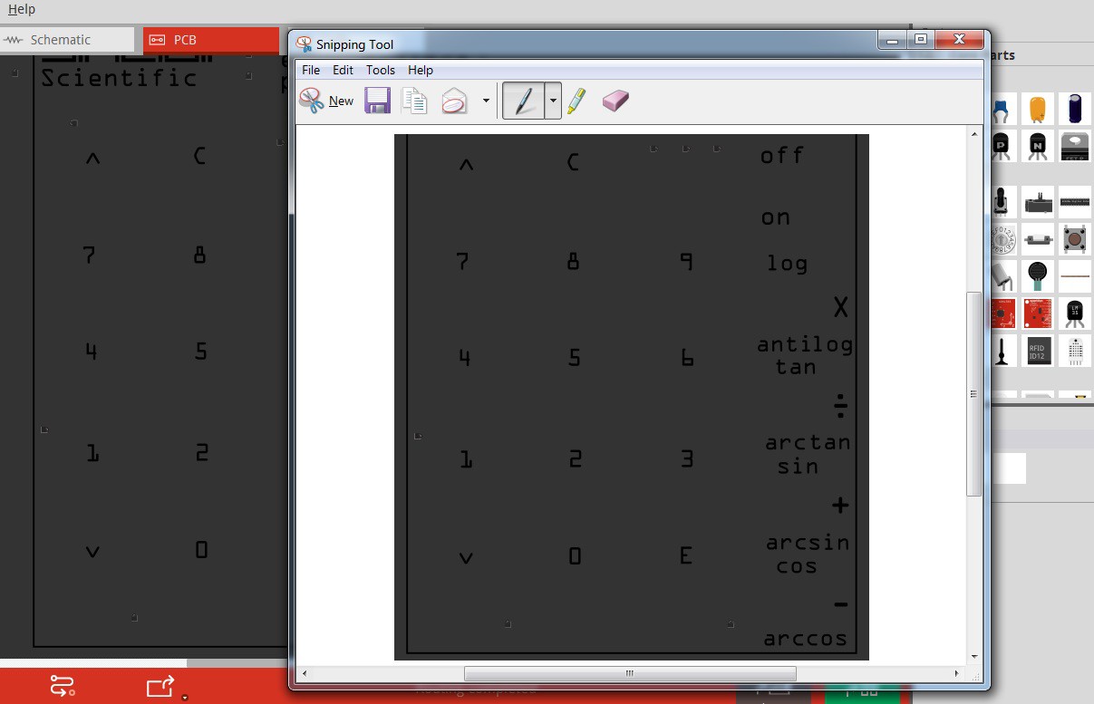
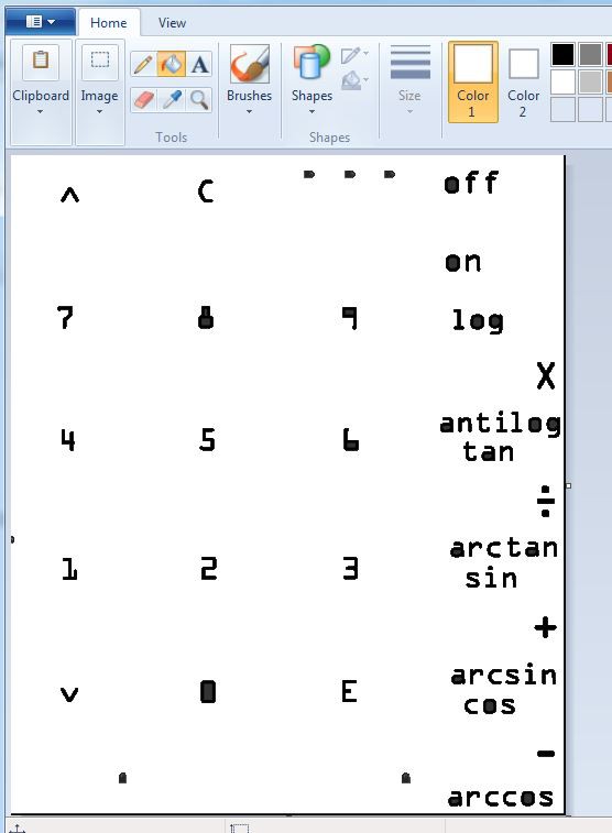
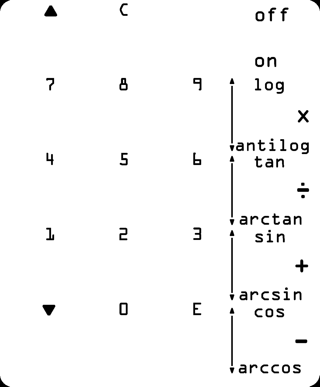
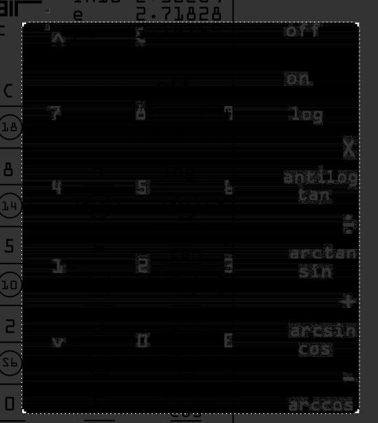
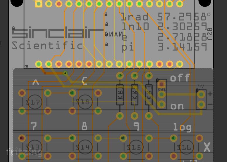
Over time, the PCB has evolved, over two iterations the width has been reduced to match that of the original calculator. The keyboard on the latest version is dimensionally accurate. Its keys line up with the buttons on the real calculator.
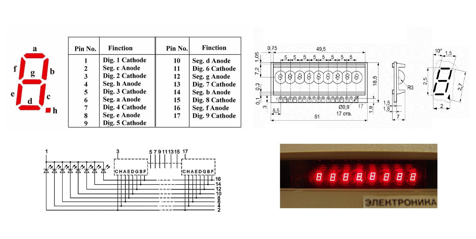
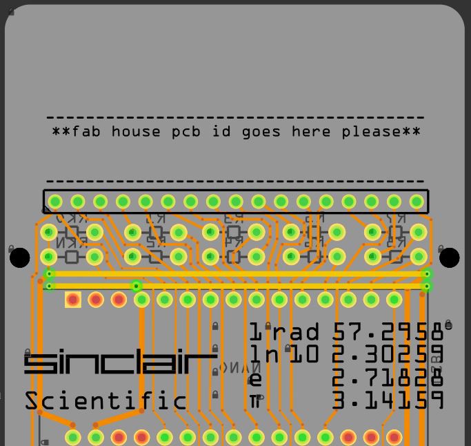
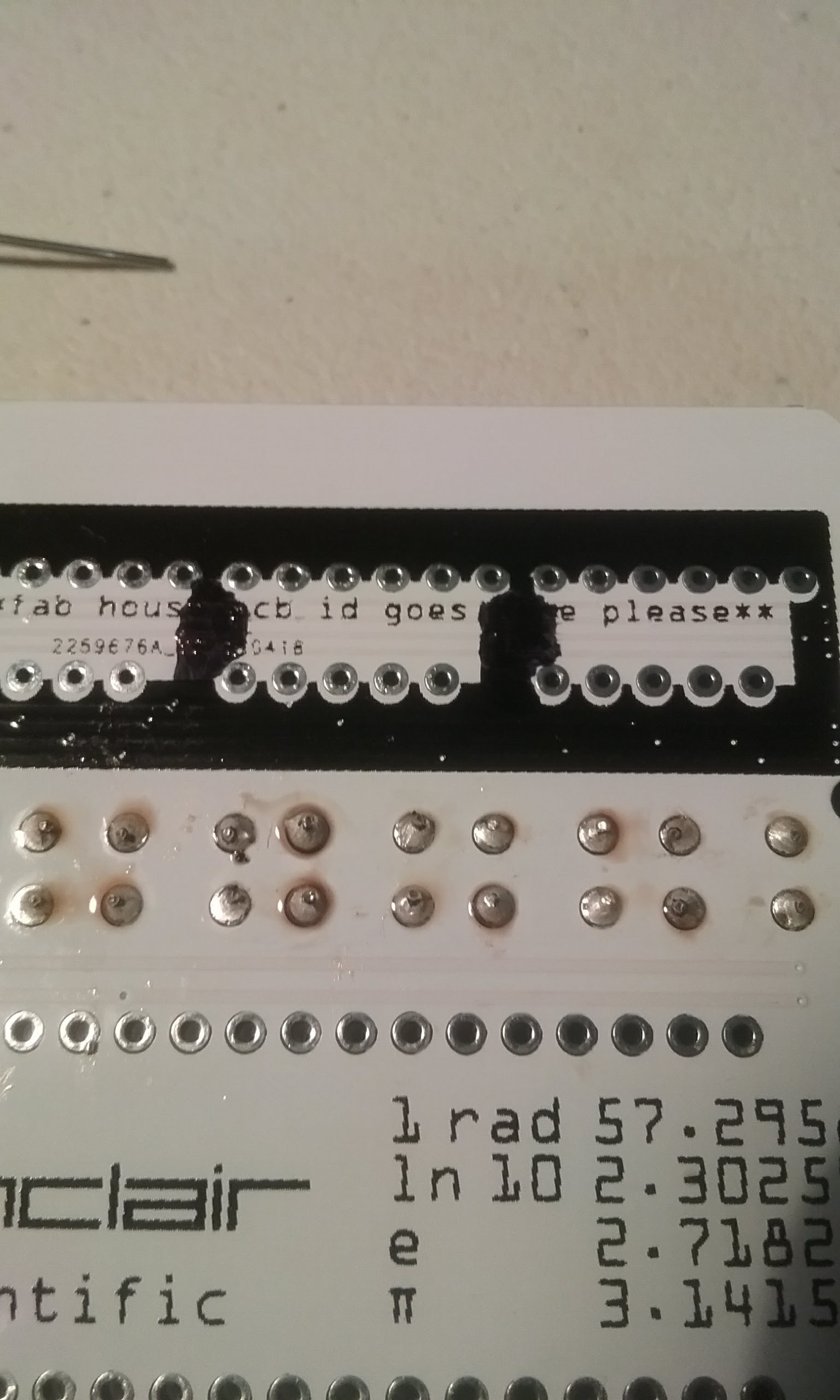
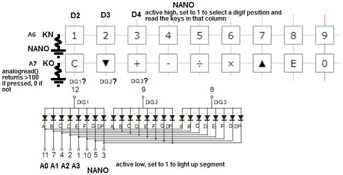
By experimenting with a real Sinclair Scientific calculator, the connections between the keyboard and the display digits were deduced. An accurate schematic has been created, its correctness verified by pressing simultaneously multiple keys on the calculator and observing that the display glitches in the same way in the original and the emulator.
This has turned the V5 and V6 PCBs into the most accurate emulators out there.
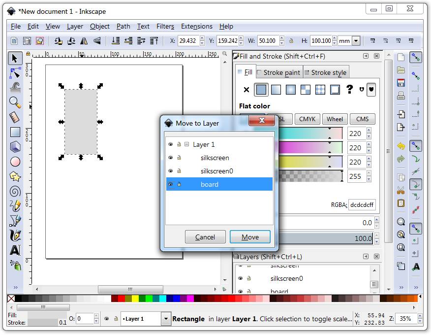
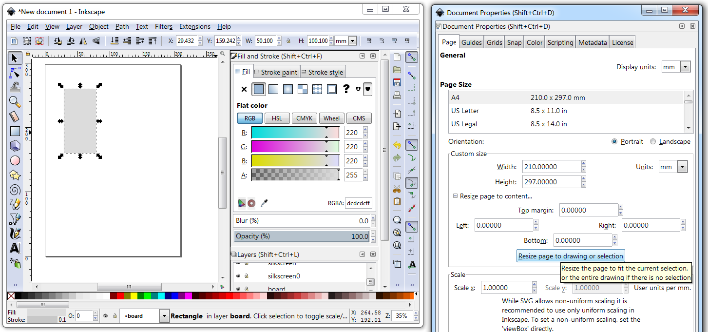
The V5 PCB is limited in height to 100mm so it can be manufactured inexpensively.
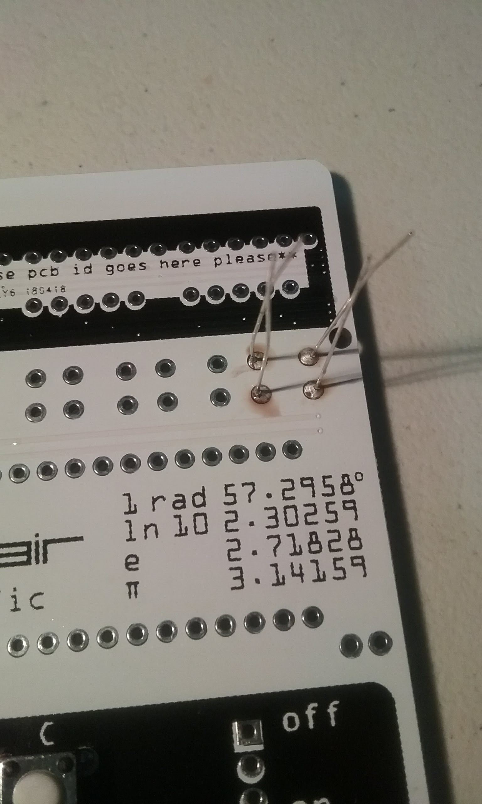
The V6 PCB has the same accurate keyboard and display circuit as V5 and is also dimensionally accurate at 110 x 51mm.
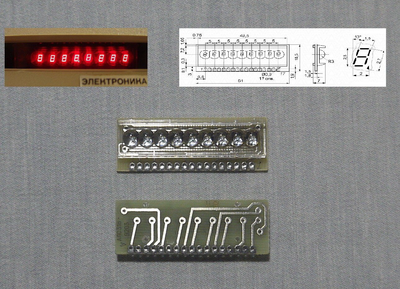
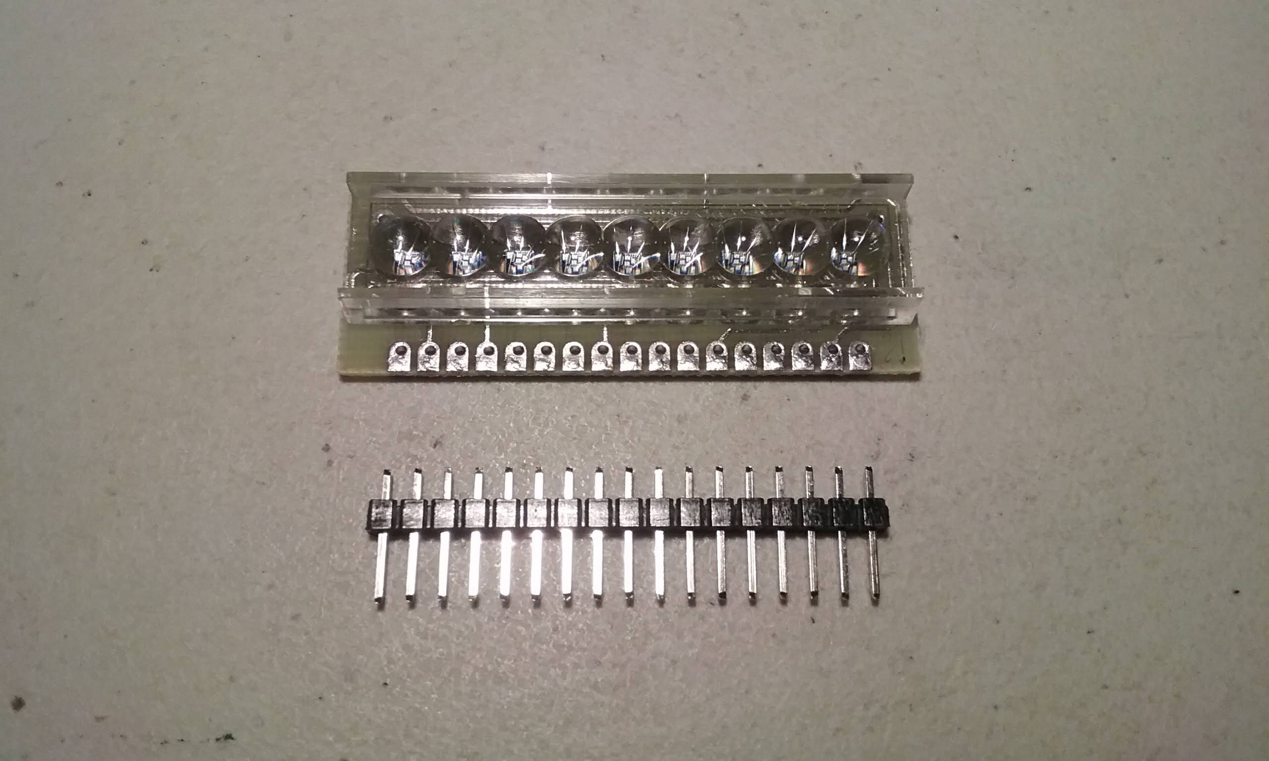
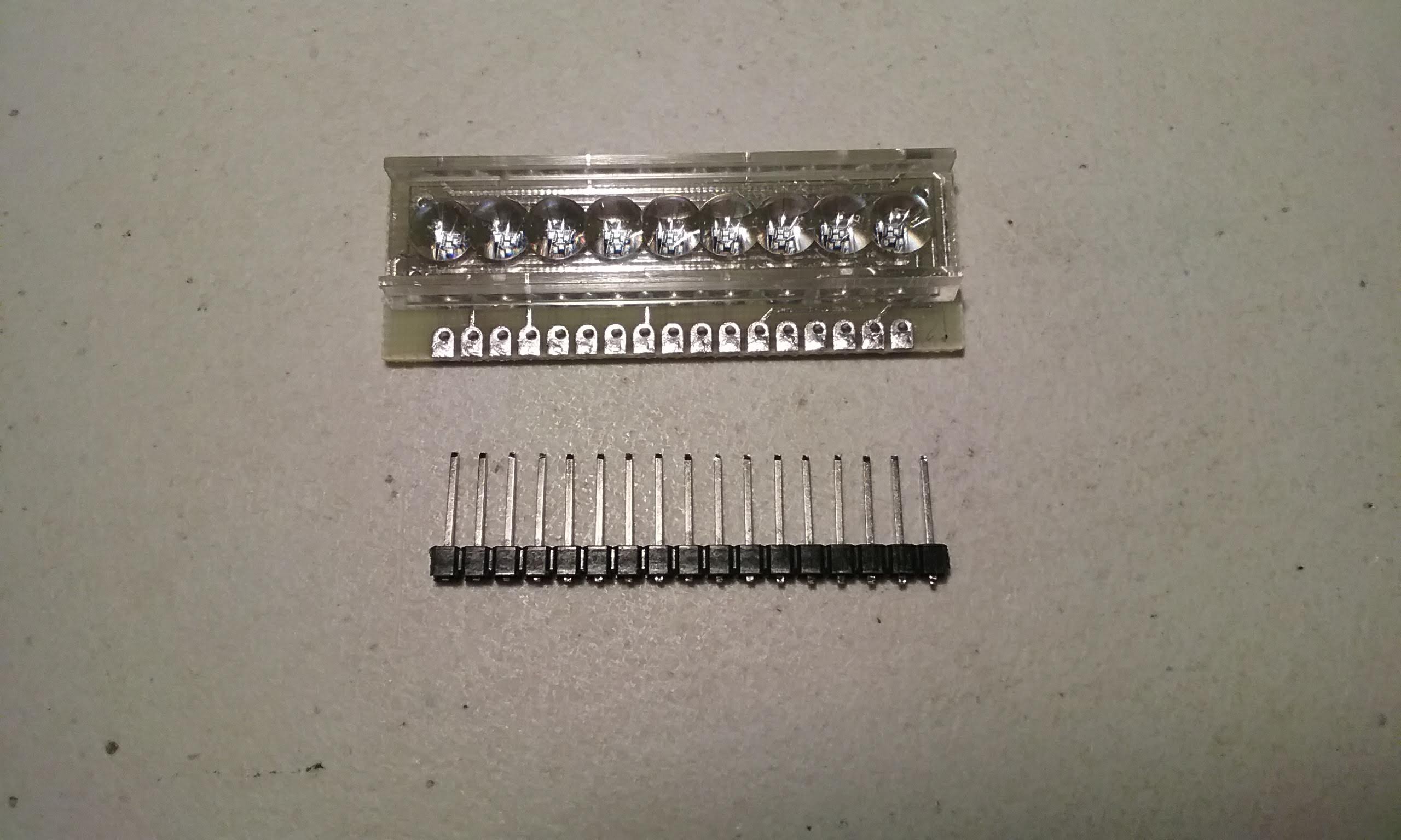
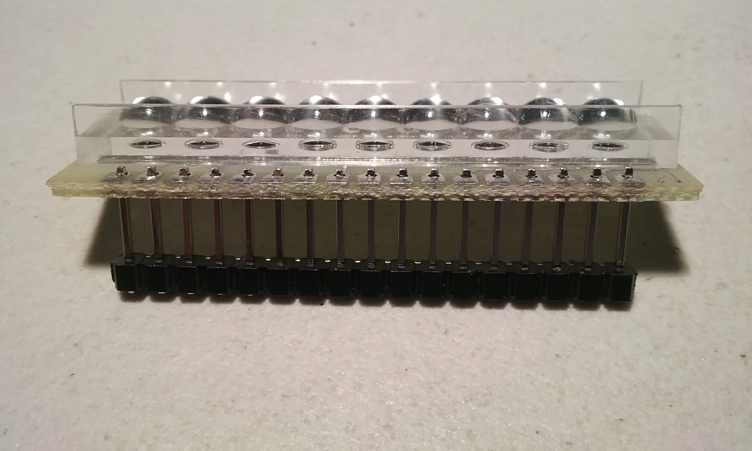
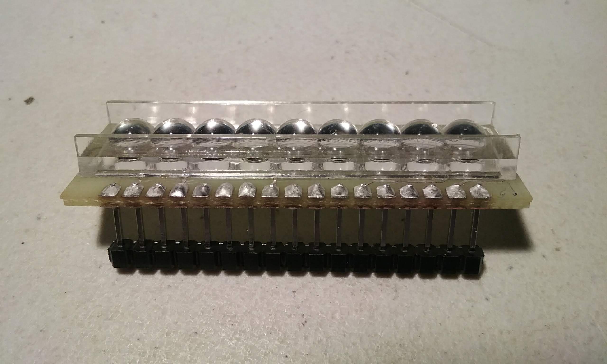
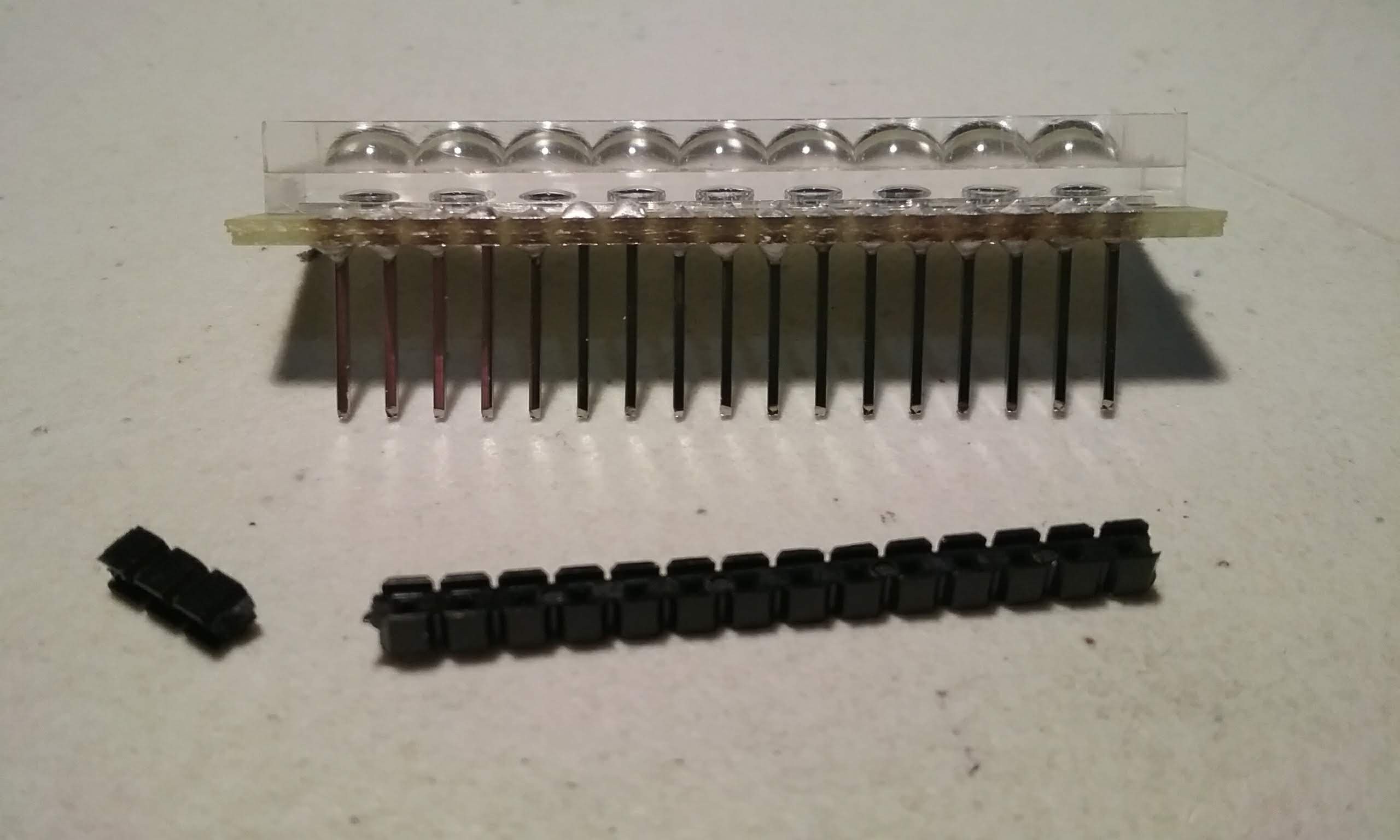
A version using bubble LED displays is in the works depending on the continued availability of those modules.
Open Source Licenses:
The original TI / Sinclair simulator is licensed under GPL v2 so the Arduino port is also licensed under GPL v2
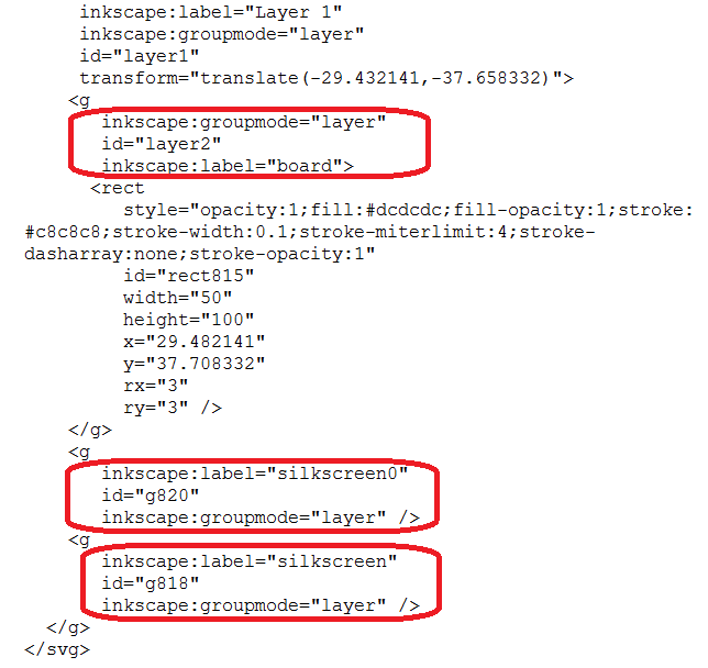
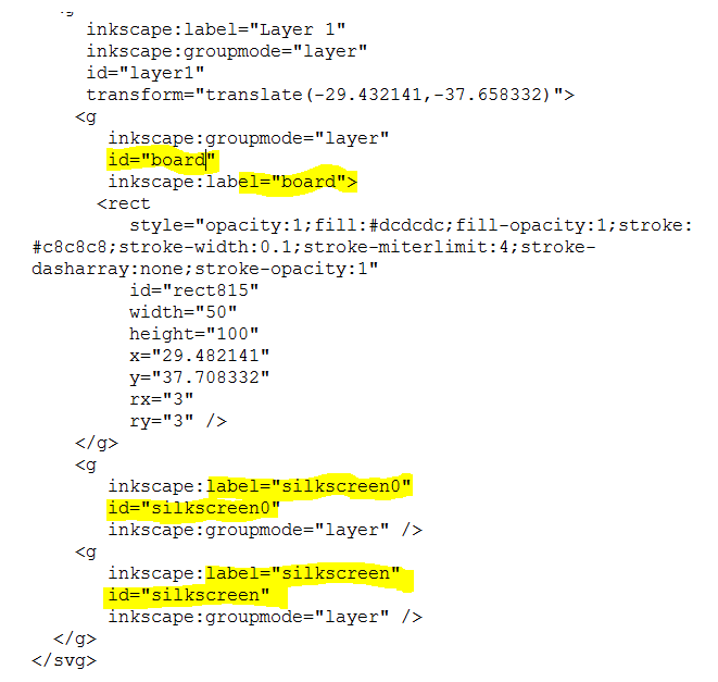
The PCB files are:

Sinclair Scientific Calculator Emulator by @ArduinoEnigma is licensed under a Creative Commons Attribution-ShareAlike 4.0 International License.
Based on a work at http://righto.com/sinclair.
Project Logs in chronological order:
11/17/2017 - The keyboard is designed.
https://hackaday.io/project/91895-sinclair-scientific-calculator-emulator/log/121215-11172017-the-keyboard-is-designed
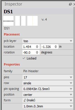
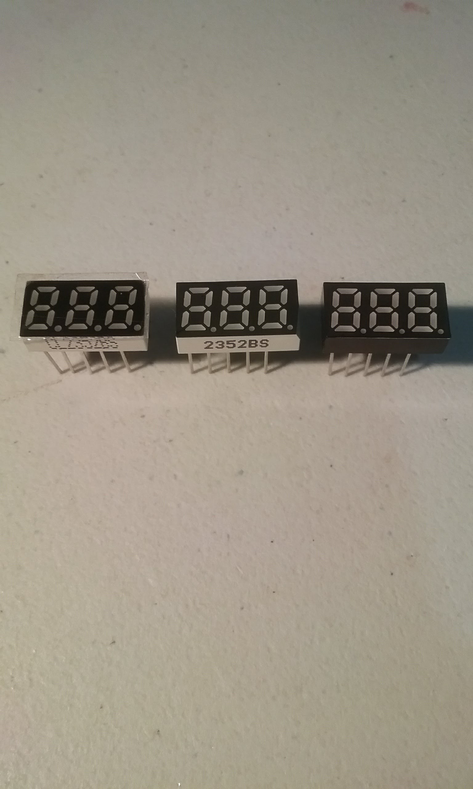
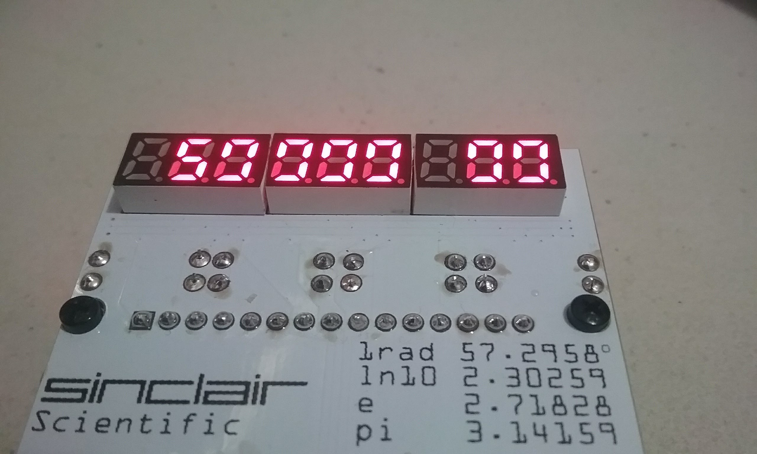
12/21/2017 - A suitable display is found, design of the PCB continues.
https://hackaday.io/project/91895-sinclair-scientific-calculator-emulator/log/121370-12212017-a-suitable-display-is-found-design-of-the-pcb-continues
12/23/2017 - Putting the Display and Keyboard together.
https://hackaday.io/project/91895-sinclair-scientific-calculator-emulator/log/122095-12232017-putting-the-display-and-keyboard-together
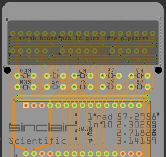
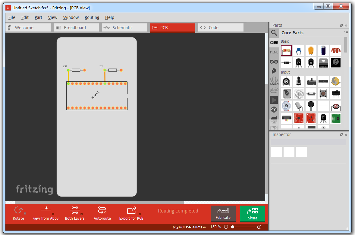
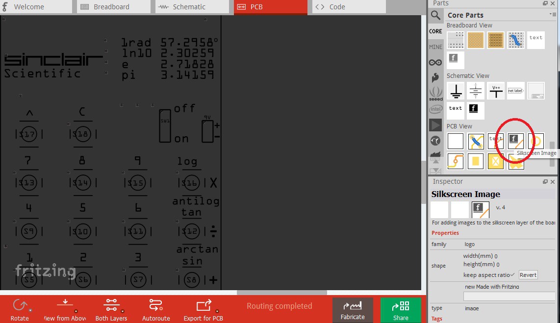
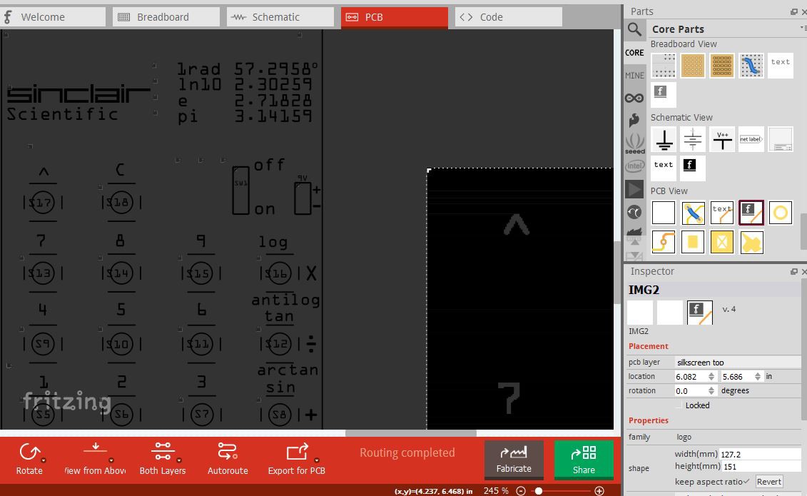
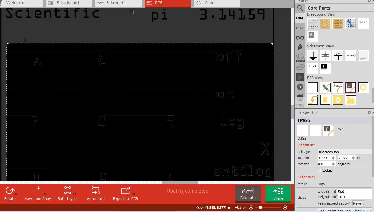
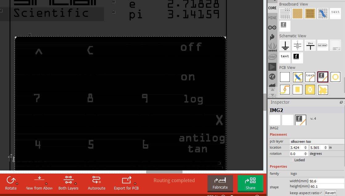
12/25/2017 - Finished Routing the Board and Submited for Production (how to do tented vias in Fritzing)
https://hackaday.io/project/91895-sinclair-scientific-calculator-emulator/log/123664-12252017-finished-routing-the-board-and-submited-for-production
12/30/2017 - The desire to design a slimmer version begins
https://hackaday.io/project/91895-sinclair-scientific-calculator-emulator/log/125443-12302017-the-desire-to-design-a-slimmer-version-begins
01/03/2018 - The manufactured V1 boards arrive
https://hackaday.io/project/91895-sinclair-scientific-calculator-emulator/log/125513-01032018-the-manufactured-v1-boards-arrive
01/05/2018 - V1 is assembled, a problem appears
https://hackaday.io/project/91895-sinclair-scientific-calculator-emulator/log/125515-01052018-v1-is-assembled-a-problem-appears
01/06/2018 - Work on the Arduino port of the TMS0805 Simulator continues
https://hackaday.io/project/91895-sinclair-scientific-calculator-emulator/log/126356-01062018-work-on-the-arduino-port-of-the-tms0805-simulator-continues
01/07/2018 - Using a fast pin library to improve performance
https://hackaday.io/project/91895-sinclair-scientific-calculator-emulator/log/126425-01072018-using-a-fast-pin-library-to-improve-performance...


 RasmusB
 Jacob Still
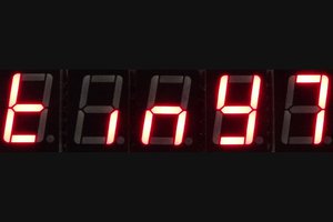
 Alex
Alex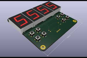
 Ken Yap
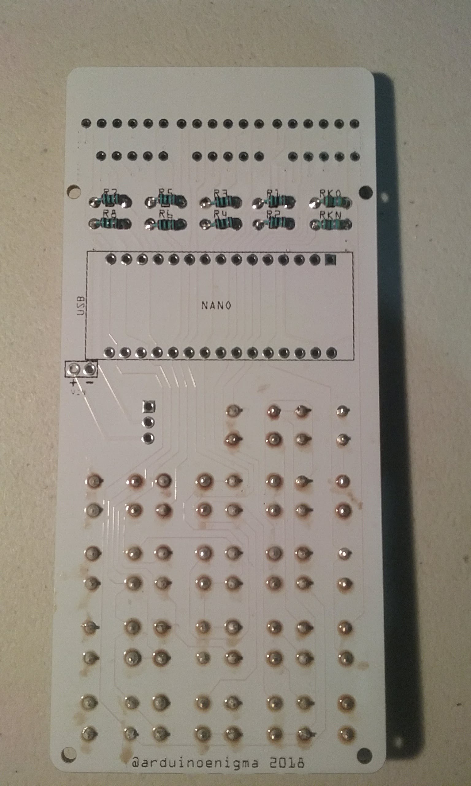
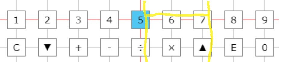
I have an issue with this one. I built the first one and it worked like a charm. Then I built a second one with the same exact parts for a friend. Everything works except the "1" key. The "1" does not register. Actually, it registers and blanks the screen to zeros, as if I had pressed CLEAR. I replaced the key with another one, traced some of the connections, but could not find anything wrong.
Any suggestions anyone?
Thanks,
Telly