This was the first solution I was planning to implement based upon this Instructable. It is the "SunFounder 2 Channel 5V Relay Shield Module for Arduino UNO 2560 1280 ARM PIC AVR STM32 Raspberry Pi" for about $7 via Amazon.
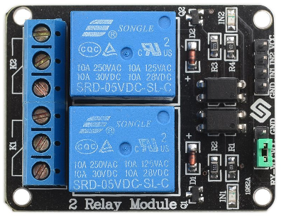
- (2) High-current Relays
- Input: 5VDC 15-20mA driver current
- Output: 28-30VDC 10A / 125-250VAC 10A
- Relay output status LEDs
- Optically isolated
- Active LOW
Concern:
The major drawback to this module is that it is Active LOW, meaning this relay triggers from NC to NO by driving the input to GND. Depending on application, this isn't a big deal to invert logic in controller, or it may even be the desired solution. However, w/ this particular project, if the RPi were rebooted (due to power flicker/outage, etc.) it would possibly trigger the garage door to activate during the bootup process. Not a secure solution--particularly if we are away/asleep when this happens, and it opens the door.
If you do enough reading in the Instructable's comments and this product's Amazon customer reviews, that's a common observation/complaint. Granted, folks overcame this by inverting the signal w/ a transistor or implementing a pull-up resistor, or implementing some other such additional physical circuitry. In my case however, I prefer to keep the entire system as compact/simple as possible--meaning fewest number of boards/modules.
If my next relay option doesn't work out, I may return to this board and first try the pull-up resistor technique. This is most likely the correct reasoning here, b/c when the RPi is booting up, the pins are floating somewhere between HIGH and LOW, and it's just the luck of the environment conditions whether the relay will be triggered or not.
Discussions
Become a Hackaday.io Member
Create an account to leave a comment. Already have an account? Log In.