 zakqwy
Okay, time to get serious about figuring out if GimbalBot will ever fly. That means doing some static thrust tests on the propeller; and not just one, but two, in a coaxial contra-rotating configuration. Oh yeah, and with the propeller nuts facing each other, like they will in the final model.
I had originally intended to use the 4' chunk of rectangular aluminum tube I picked up last week to build a simple balance. I hadn't really figured out details on the actual motor connection, since I wasn't entirely sure how I was going to mount the motors. I've since decided (as of v05 or so) to use brackets cut from commercially available CFRP angle stock, as shown in the close-up picture below:
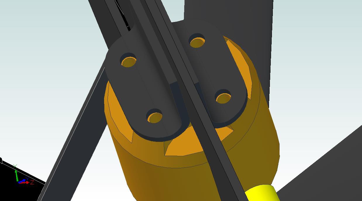
(note that the brackets are slightly offset, as the motor's bolt pattern is a 'helpful' trapezoid. Also, the holes aren't perfectly aligned due to my subpar CAD modeling skillz.)
So... now that I have this designed, why not use that as a method to constrain the motors during static thrust testing? It would also give me a chance to test my space glue! Now I just need a way to affix that assembly to the aluminum tube without building the entire GimbalBot frame.
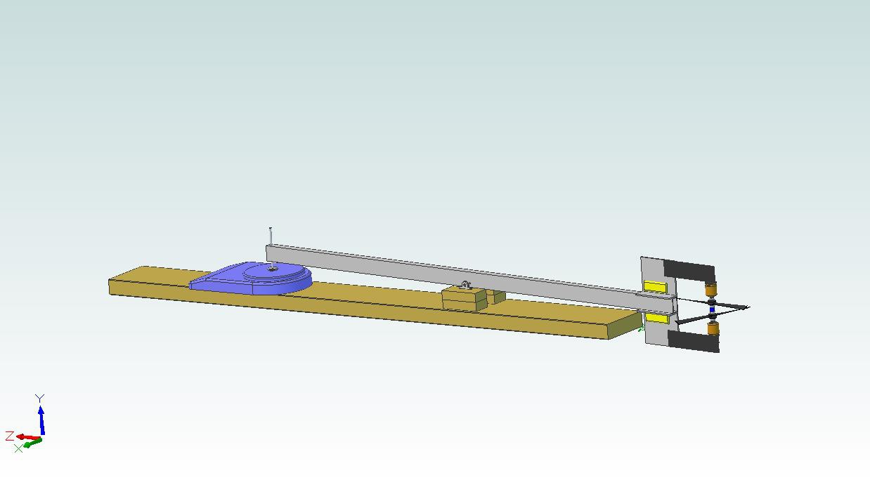
First thought (poorly cropped):
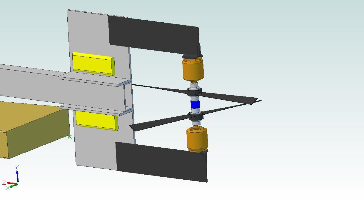
Close-up of the motor assembly, including the brand-new Jefito bearing (highlighted in blue):
Some of this design was driven by the wood I have stashed in my basement, and the cheap-but-adequate desktop scale I bought for a corporate pinewood derby competition (yes, they have those, and no, I didn't come close to winning). In practice, I'll (a) clamp it to my workbench, (b) hide behind something when I first turn it on, (c) make sure the center of rotation is the same distance from the pivot as the adjustable peg that contacts the scale, and (d) preload the scale to a few hundred grams to guarantee good contact. In addition, I'll be measuring current draw from the ESCs at 12vdc; if the extra computer power supply I have lying around can't provide enough juice, I might have to swipe my car battery for the test.
Most of the needed parts have been ordered. Looking for recommendations on the Jefito bearing; I need something that can handle 30k rpm or so in a compact package. The short length of the CFRP motor support is based on existing stock I have; I might end up using something else (i.e. longer) so I can get a better connection to the mounting bracket.
Anyone think I'll actually get good data?
Discussions
Become a Hackaday.io Member
Create an account to leave a comment. Already have an account? Log In.
Are you sure? yes | no