 zakqwy
As I wait for parts to build the propeller thrust testing jig, I want to dive into one of the primary design constraints that has driven many of the decisions illustrated in the various CAD models. Way back in early May, I showed a revised frame design that included a slip ring; the intention behind this device is to allow Rho to rotate freely though 360 degrees without having to back up and unwind the thruster motor power leads. As discussed in greater depth in that post, I'm not concerned about individual thrust vector changes; realistically, dRho and dTheta shouldn't be too high for a given control change. However, I don't want to worry about Rho hitting the limit of its range of motion after a sequence of unidirectional corrections, as the 'unwinding' procedure wouldn't be instantaneous and would result in the fan gimbal crossing unwanted thrust vectors.
While I've been piecing together the CAD model from other various constraints (the Theta servo and standard CFRP plate dimensions, for example) I've also been shopping around a bit for off-the-shelf slip ring options. More discussions with Curtis suggest that Moog makes a wide selection of decent units, so I started rooting through their catalog to see what is available. Generally, I wanted something as light as possible, with minimal cross-sectional area, that would handle the current and voltage needs of the thruster assembly. Additional bonus features would include (a) low connection noise so I could send control signals through the ring (rather than a short-range RF link); (b) low static and dynamic friction; (c) long-life; and (d) [this one is a stretch] some axial- and radial- load handling capability.
So what's out there? Lots. Mercury wetted stuff seems like it has some good features: low noise, low friction, great capacity for a given size--but they have more stringent mounting orientation requirements, probably to keep the Hg in the right spot. The bigger issue in general, however, seems to be in current and voltage ratings: as a rule, it seems like these devices are rated for lower currents than I need at my voltage range. Bumping the current capacity up sufficiently makes the device hilariously large, as I end up with something rated in the low kilowatts.
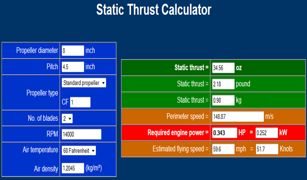
Time to run some numbers, working backwards from the thrust calculation site I found some weeks ago.
Based on the 12x12" CFRP sheet constraint (and the need for a fair amount of width on the pitch ring), I figured that the largest diameter prop I could fit is 8". Targeting ~1kg thrust per propeller, the calculator suggested I would need to spin around 14k RPM, which (assuming a lot of things about the propeller, not to mention ambient air density and so forth) would require ~250 watts of motor power:
Getting back to real-world thrust testing, I'm concerned about how two contra-rotating propellers will 'stack' in terms of thrust (some literature I briefly studied suggested 20-30% loss, and net value would likely depends on more variables than I could realistically model); either way, I wanted a decent amount of overhead, so I decided to (a) size the motors for higher wattage (and RPM) capacity, and keep the overall system weight minimal even if on paper it looks like my thrust:weight ratio is decent.
So... call it 600 watts for a pair of motors. Most brushless stuff I'm looking at is sized for the RC world, meaning 2-4 series-connected LiPo batteries. Think voltage in the range of 10-20 VDC, give or take. That means 30-60 amps at peak power demand. Not a lot of slip rings available that are optimized for that specific voltage and current range: as I alluded to above, a 60 amp slip ring might be rated for 250 volts, and they tend to be quite large.
Another great suggestion from Curtis: voltage conversion. What if I sent a higher voltage at a lower amperage through the slip ring, then stepped it down for the motors? I mulled this over a bit and realized that I could string together a bunch of small LiPo batteries (so I wouldn't need to step-up too), dump high voltage/low current through the slip ring, then connect that to a voltage converter small enough to fit on the motor plate. I didn't think that would happen, but a deep dive into various catalogs produced an ideal unit from GE's Critical Power division. The device is rated for 52-60 VDC in/12 VDC out at 600 W, and it's the size of two motor controllers! The unit does have cooling airflow requirements, but I'm not too concerned about that--after all, it'll be mounted right above two propellers:
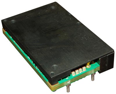
Once I found that GE device (it's the mysterious black box mounted to the motor plate you might have noticed if you've opened up a recent CAD model assembly), I was able to select a reasonable slip ring; the unit I'm using has tons of circuit pairs, but I'll parallel most of 'em together to handle the motor load. I'll also probably send lower voltage to power the ESCs and servos, and probably to try control signals too--hopefully that works and I can dispense with the wireless link. K.I.S.S., right?
12vdc out of the GE unit drove the decision to spec a pair of 1250kv motors: at 12v, I'd hit 15000RPM, and the corresponding current is right at the limit of the power converter. On paper, it seems like everything adds up; I've said it before a few times, but the project really does come down to thrust testing at this point.
That's where we stand. My challenge now is getting my hands on the hardware; I reached out to GE in several ways and eventually got a call from a local rep, who is working to get me two units. These devices are only sold in case quantities through my normal distribution channels, and I don't want to buy 24 of 'em just to use one. Likewise with Moog: no response on pricing yet, so hopefully I hear back soon.
Anyone have any thoughts on a better way to do this? I'd love to avoid using a converter altogether, but 60vdc brushless motors (that hit my size and power requirements) seem to be tough to find, since there aren't many quads that use 16S LiPo configurations. I don't think building my own converter makes sense, since that's a pretty intense engineering effort by itself and the GE device appears to have excellent power density.
Discussions
Become a Hackaday.io Member
Create an account to leave a comment. Already have an account? Log In.