 zakqwy
I did a bit of assembly work today on the thrust testing rig. First thing's first: I needed to cut down the prop nuts (there must be another term for these) since I need the motors as close together as possible:
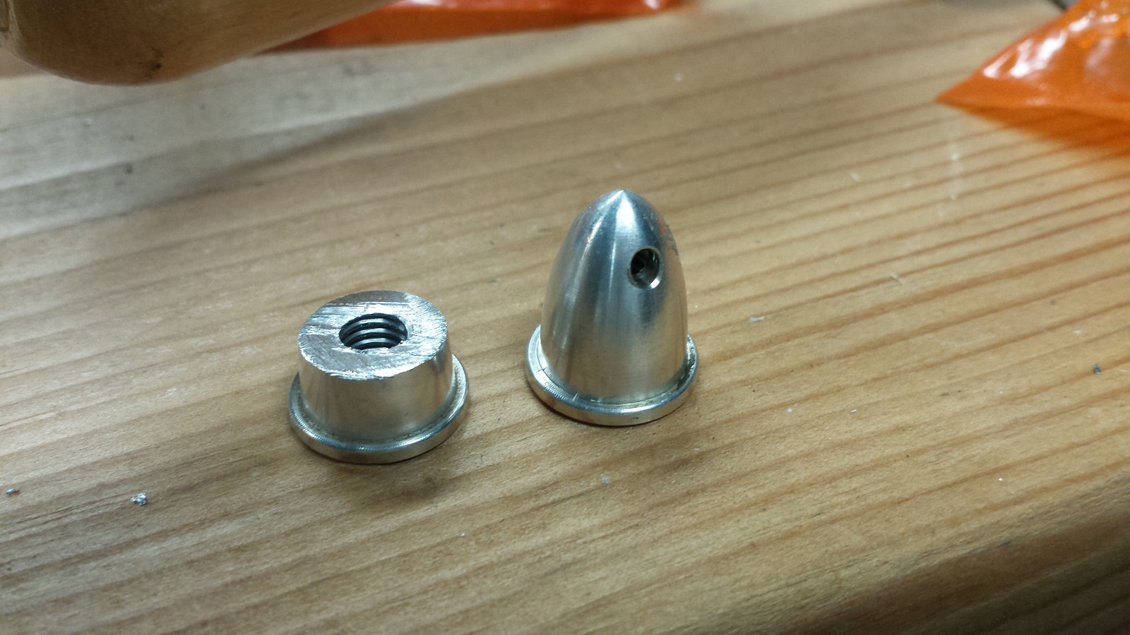
I filed the cut edge down a bit, but I suppose I might need to hit it again if the balance is upset too much.
Other than copious amounts of painter's tape sticking to the CFRP angle stock, the space glue seems to have done its job. I drilled a few holes (see previous post regarding PPE), re-drilled a few holes, slotted a few misaligned holes with my Dremel, and eventually cobbled together the 'business end' of the thrust testing rig:
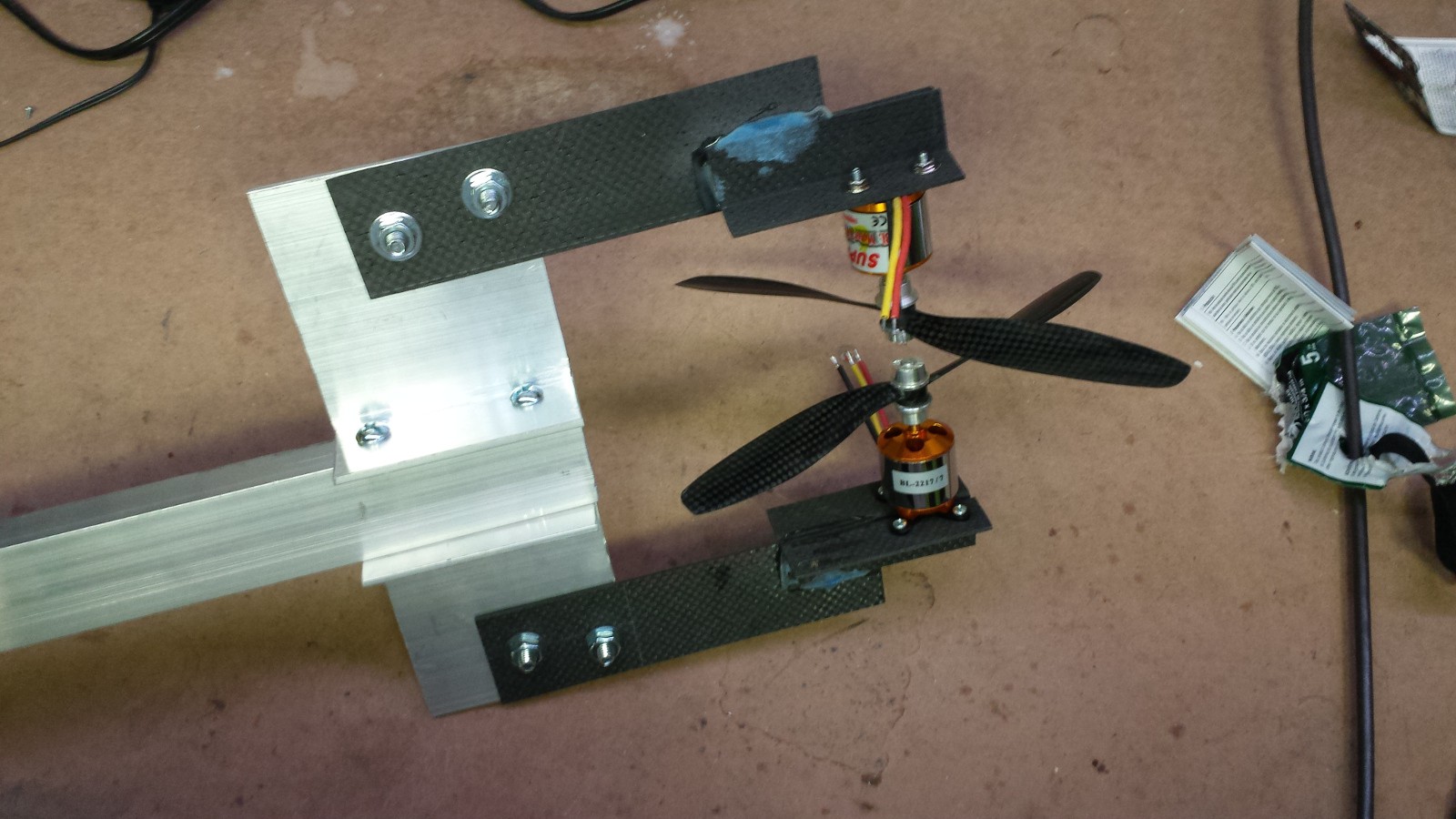
It's like a weird 4-foot-long trident dealie with crazy propellers on the end. Or the eye of Sauron, if you replace the fiery center with rapidly spinning blades of death. Either way, definitely one of the odder contraptions that's come out of my basement.
No testing yet, but that will come soon. I have a 30amp/12vdc power supply that will conveniently not power both motors, but I'll be able to at least get them spinning. First observation: as Jefito reminded us in late May, the plates lack lateral stiffness. It's quite easy to push the propellers sideways, so I'm curious to see what happens at 15k rpm. I thought about gluing on some reinforcing strips to stiffen up the CFRP plates, but I'm inclined to run the rig up to a few thousand revolutions first to see how badly it vibrates. So what will fail first: the glue joint or the plate itself? Or will the bolts just back themselves out and fly apart? Stay tuned..
Discussions
Become a Hackaday.io Member
Create an account to leave a comment. Already have an account? Log In.