 zakqwy
I had a lengthy conversation with Jefito yesterday evening and ended up spending some time doing a bit of CAD work. He brought up motor cooling; specifically, the fact that I might be able to get better performance out of my brushless motors if I could figure out a way to cool the stators during operation. He had a few ideas beyond simply increasing airflow, including some novel thoughts featuring dry ice or liquid N2. Definitely worth considering, as GimbalBot's flight time probably means the few minutes of coolant I could carry would be adequate. It's been many years since I've used LN2 in a personal project and I've been looking for an excuse to find a good MN supplier.
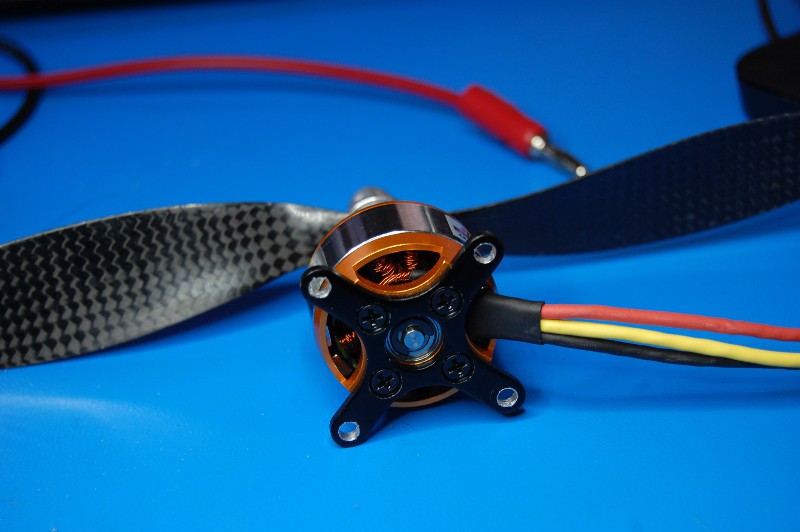
However, we ended up discussing air cooling as a simpler alternative. I came up with an idea for directing additional airflow into the back of the motors, taking advantage of the fact that they already have large cooling passageways machined into their backs (with vents opposite those holes on top of the motor rotors):
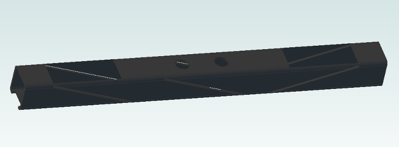
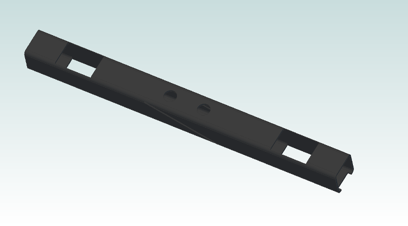
Using the hollow CFRP motor mount as a duct, I used a series of diagonal slots to orient three CFRP plates to deflect airflow. I also cut a few holes where the motor sits (and in the CFRP motor mount plate, not shown) to direct airflow into the two motor cavities:
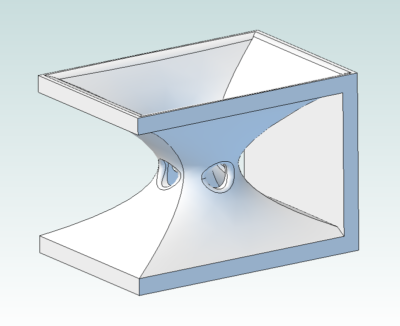
Here's a confession--I've never done a 3D printing project. I've certainly played around with 3D printed stuff, and hit the button to run a stock program or two; in college we had a Z corp SLS setup that we used for resin bonded sand, but it was being used for things quite a bit so I set my sights elsewhere. Since then, I've always gotten hung up on details like machine/material cost and the structural deficiencies of commonly available rapid prototyping compounds. In this case, however, 3D printing is the perfect fit for a few nozzles:
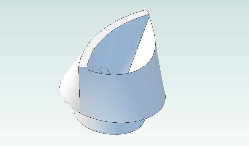
Yaay fillets!
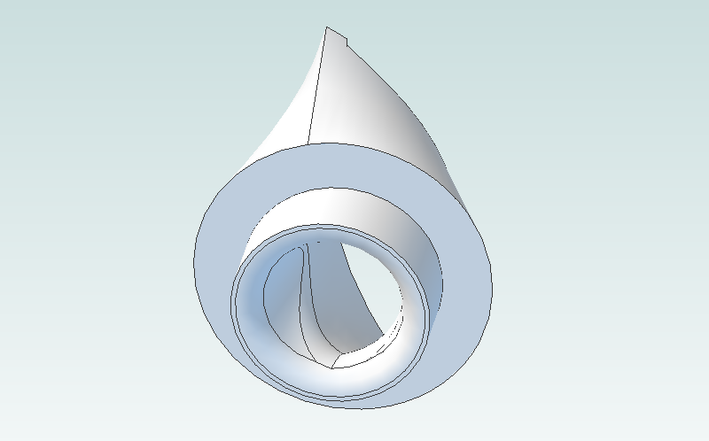
I dropped the opacity of the motor down a bit so the fit between the nozzle and the motor/mount makes a bit more sense:
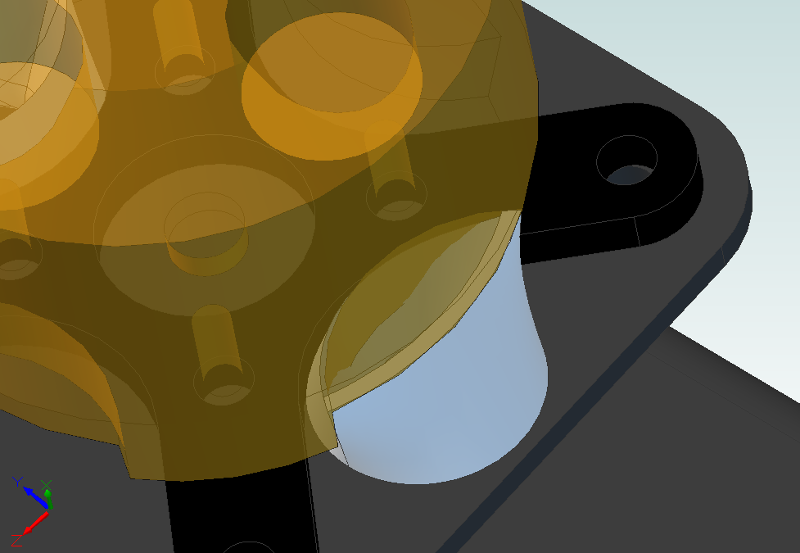
I need to tweak the dimensions a bit, mostly because my original measurements of the motor vents weren't intended to be highly accurate. But you get the idea:
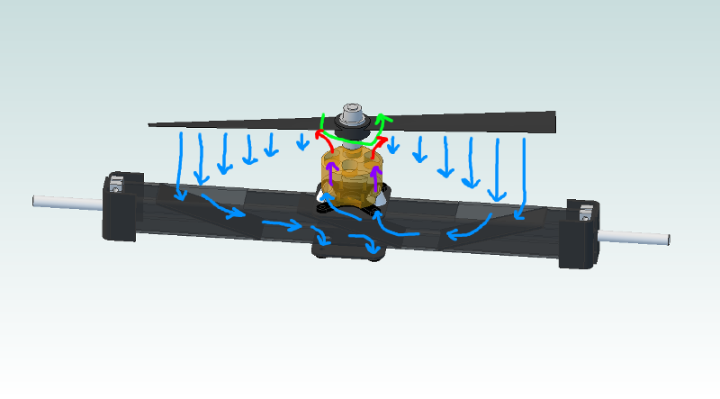
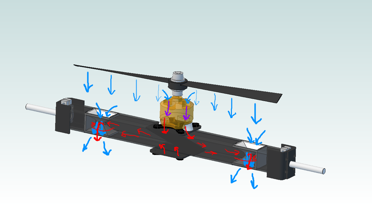
Sorry about the crudely annotated drawing. Green is motor rotation, blue is cold air (with length somewhat proportional to velocity), and purple and red are air getting progressively hotter as it travels through the motor. The idea is that the air velocity below the propeller is not uniform; instead, the velocity increases as you get to the perimeter of the blade:

source: http://www.gorhamschaffler.com/system_effects.htm
Or at least, that's what my understanding of propellers suggests. This design is intended to capture some of that high velocity air and send it back through the motor. Think the pressure above the motor will be low enough to cause a decent amount of air to move? Or am I naive to assume that the velocity profile of the air coming off the fan blades can be described so simply, without accounting for the myriad of factors (distance from propeller, airflow disturbances caused by the frame, propeller shape, lack of duct compared to the picture above, etc) involved in a good simulation? If I follow this plan, I'd cut a fairly large hole in the CFRP motor mount and run instrumented cooling tests at a constant thrust (or current) with various inlet opening sizes and locations.
So here's another thought: What if I design a venturi that will pull air through the motor and exhaust it through the CFRP motor mount? I'd still use the same nozzle, but the motor frame might look more like this:
Then it's time for a bit more 3D printing:
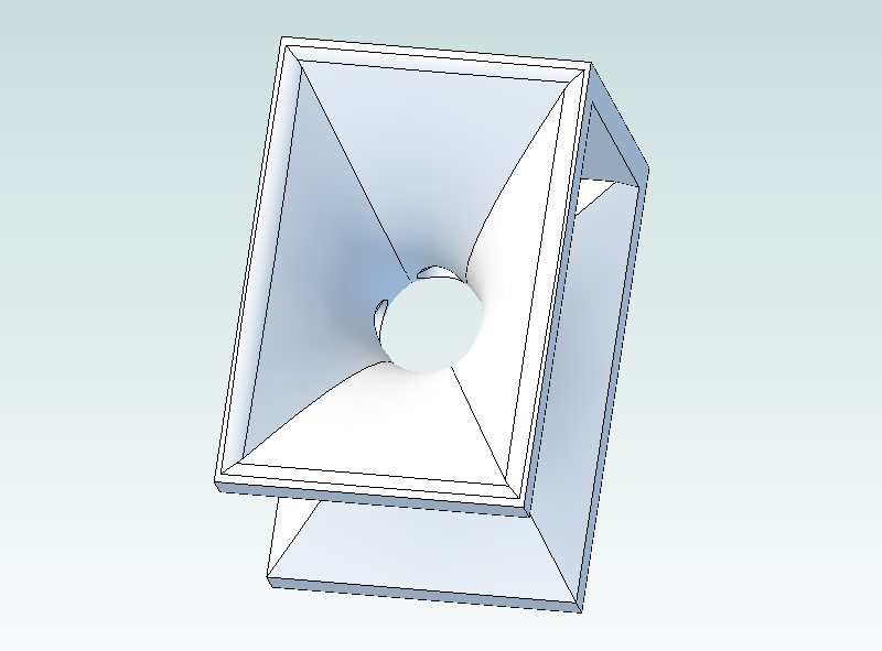
These little guys fit into the motor mount like this, with air velocity now represented by line thickness instead of length:
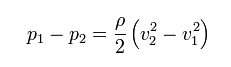
If you aren't familiar with the venturi effect, take a read through the Wikipedia article. Essentially, Bernoulli's principle says that conservation of mechanical energy along a streamline (along with a few assumptions about the fluid, such as incompressibility or at least fairly low speed) means potential and kinetic energy can change, but must sum to be the same figure. If you do the math, you'll find that the velocity of a fluid traveling through an orifice is proportional to the square root of the pressure drop across that orifice, corrected for fluid density:
source: http://en.wikipedia.org/wiki/Venturi_effect
where p1 and p2 are the high and low pressure ports, rho is the fluid density (assumed constant throughout the system--i.e. incompressible) and v1 and v2 are the velocity at the narrow and wide point in the system. So... I've got a high velocity jet of fluid (air) being forced through the venturi by the propellers, and the four low pressure ports are near the vena contracta. The pressure differential between this point and the top of the motor stator should give me some flow through the cooling system. Again, I'm hoping that the holes above the motor will provide an adequate high pressure side to generate flow through the venturi.
So--I'd love to hear some thoughts on this before finalizing dimensions and sending the 3D printing order out. I'm actually fairly comfortable sizing a venturi, since I spent a few years selling industrial differential pressure based flow meters (amongst many other types). I'll need to make a few assumptions about things like velocity, but I should be able to get a rough idea of beta ratio (the ratio of the constriction diameter to the entrance diameter) and port cross sectional area. I think it's a better solution than the flow diverter model since it should have a much less severe effect on the propellers, and I'm much more confident that I'll be able to achieve an adequate pressure differential across the stator to generate some airflow. Having said that, the turbulence and general sketchiness of the airflow that close to the propeller could cause all sorts of unpredictable effects that make the system fail miserably.
More to come on this tangent, I assure you! Comments?
Discussions
Become a Hackaday.io Member
Create an account to leave a comment. Already have an account? Log In.
Without reading all of your posts on how you selected the motor for your application... are you driving it harder than how it is specified by the manufacturer? I wouldn't be too worried about noticing a smell unless you are knowingly pushing it beyond its specs. Definitely take some temperature measurements before going crazy with a cooling system. Anything you do for a cooling system (using a shaft mounted impeller or diverting airflow from your main thrust) is going to reduce your overall efficiency so you should definitely be sure that you need it.
Keep it up.
Are you sure? yes | no
As far as motor specs are concerned, these units are rated for 500 watts; my thrust calculator (linked in the sidebar) suggests that at the thrust values I've seen on the scale, I should be pulling well under this even with <70% motor efficiency. However, I really don't trust the motor specs; they're $23 apiece hobby units designed for multirotor applications, most of which don't see this kind of thrust per corner unless you get into massive motors. Either way, the motor rotor was _really_ hot when I ran with the 10" props. I didn't check it with a TC, but I'm fairly sure the stator wasn't happy.
I haven't seen any small brushless DC motors with built in cooling impellers, but I'd definitely look in to using one if you've seen 'em around with the right specs! I need at least 500 watts of power handling at 12k+ RPM in a package under 100 grams, give or take.
Either way, you're right about the temperature measurement comment. I was planning to take before and after temp measurements after cutting a bunch of holes in the motor mounts and getting ducts and venturis rapid prototyped; maybe I should just grab baselines NOW so I can see whether or not it's really a problem!
Are you sure? yes | no
I think going with the Venturi method sounds like a smart idea, but I'm no expert in the field. Have you considered setting up thermocouples to do a before / after on the air leaving the motors? How does the project feel now in comparison to what you expected 4 months ago?
Are you sure? yes | no
I've got a few TCs lying around that I'm planning to rig up to run some tests; if possible, I'd like to get air temperatures along the cooling duct and also some contact readings from the motor itself. The TCs I've got are bare so they should be fairly responsive in moving air, and I can datalog them with a TC amp/Arduino/serial port logger. However, I probably won't set this up until I've got a cooling system installed so I can do good before/after tests.
I didn't really know where GimbalBot was going when I first published the project in late April (or when I sketched the first drawing last October). I've had to come to terms with the fact that this isn't an engineering project; beyond a few simple calculations based on very generous assumptions, I haven't done the extensive system modeling and validation to prove out the concept before getting my hands dirty. GimbalBot is a hack. It's not the right way to tackle such an ambitious design, but I've thoroughly enjoyed the various lessons along the way. I still think I can get GimbalBot to work (even if it doesn't stay off the ground for too long), and I've learned an insane amount about a wide variety of subjects--composites, robotics, CAD modeling, fluid dynamics, power systems, inertial measurement, controls, sensor fusion, filtering, etc. Definitely happy with how things have gone to date, even if the path would have been difficult to predict a few months ago.
Are you sure? yes | no
Nope. Propellers, as shown in the photo at the top of this log entry, are twisted to compensate for that; the pitch is greater near the hub than at the tip to try to make the velocity imparted to the air and the load on the propeller's structure more uniform. The propellers in your airflow diagrams are twisted the other way, which would increase the non-uniformity. (I don't think you can buy propellers like that.) I don't think this would really impact the viability of your cooling system, though.
Are you sure? yes | no
Do you think the airflow deflector design would be a better choice than the venturi system?
Are you sure? yes | no