 zakqwy
So I've come to the conclusion that my servos were designed to actuate smaller masses, and as such their control parameters aren't exactly suited for the larger than normal loads I'm putting on them. The vibration I'm seeing at the end of each stroke--particularly for the outer servo--looks suspiciously like ringing due to an under damped loop:

source: http://woodharbinger.com/site/index.php/control-loop-tuning-for-building-performance/
It's hard to say without looking at a response waveform, but it seems like adding a bit of derivative could help tamp down the ringing a bit. Or dropping the proportional gain. Or playing around with it for half an hour, because putzing around with PID loops is actually really fun.
I got in touch with the support folks at the company that manufactures the servos I'm using; they're high end units ($150 each for hobby stuff? yup!) but they aren't explicitly programmable. It's a bit odd, and something I didn't think to ensure when I ordered them; they have lower end servos ($50ish) with lower speed/torque specs and plastic gears that can be programmed, and the top-of-the-line units (one step above mine) are also programmable. But not the series I selected.
In any case, the customer support guy gave me an unfortunate if not unexpected response--the servo I'm using isn't programmable, and it works well for the applications it's designed for. He recommended taking a look at the higher end unit as it's the highest performance device they've ever built. I told him that I wasn't interested in investing in additional servos unless the programming features would allow one direct access to the servo loop tuning parameters; needless to say, he hasn't gotten back to me yet. Oh well.
The servos are still excellent units; they're crazy fast and seem to have plenty of torque for the application. I'm afraid the ringing will give me all sorts of problems developing GimbalBot's control algorithms, so I'd like to get ahead of this now. Time to void some warranties!
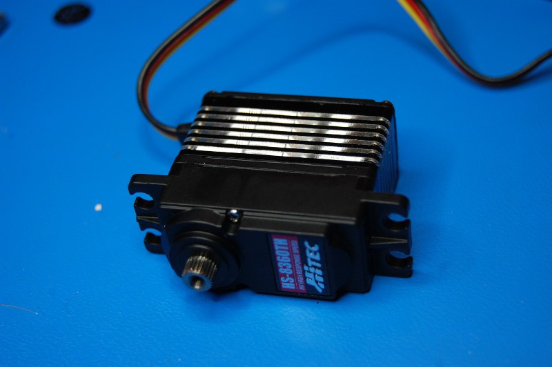
The patient:
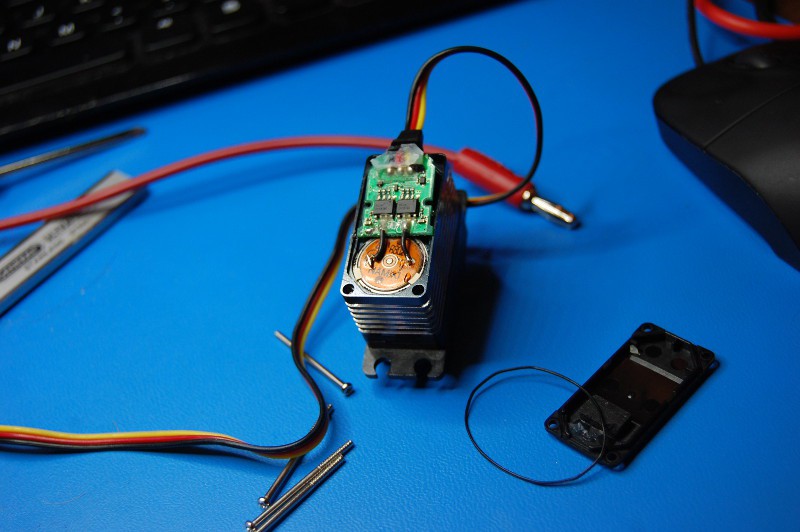
I removed four Phillips head screws and carefully pried off the rear cover; it was glued on to the circuit board pretty well, so this was a bit of a delicate operation. Lots more glue on the board:
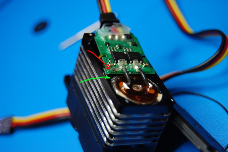
 Here's where it starts to get annoying. Yeah, more annoying than a glued down circuit board. You can see the two motor leads in the picture above; it appears that the motor also grounded to the circuit board through a third wire, barely visible in the following picture (the green arrow shows where the wire connects to the motor, while the red arrow shows where the wire is soldered to the circuit board under a heap of glue):
Curiosity quickly got the better of me, so I scraped off the glue and headed up my soldering iron. A bit of braid made quick work of the offending solder joint:
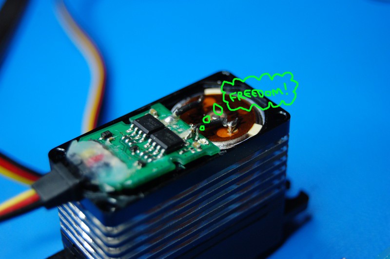
... allowing me to lift up the board:
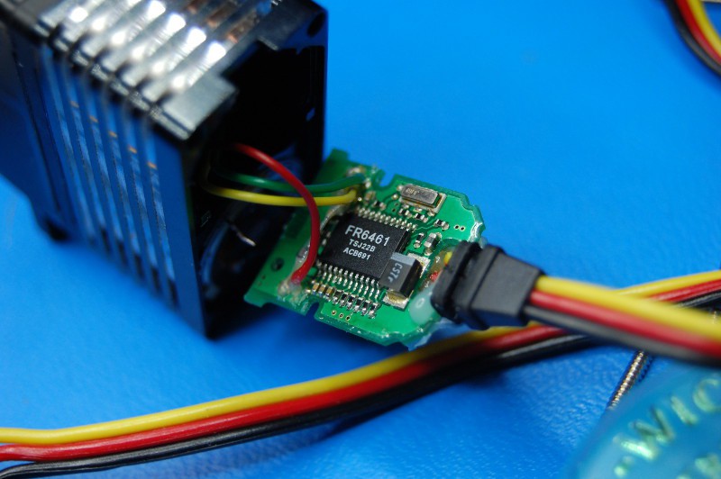
Now we're cookin' with gas. A quick Google search turns up FR6461 as a digital servo controller chip. I found a datasheet (*.pdf warning) that gave me all sorts of (potentially) good news. Take a look at this part of the datasheet:
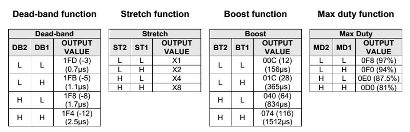
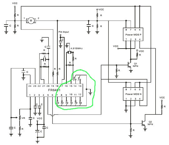
The eight configuration pins are 7, 8, 9, 10, 11, 12, 13, and 14; in the picture above, you can see the first six are tied directly through six black components to a copper plane, which has vias that carry it to the servo ground lead. The other two pins are similarly connected on the other side. That means, assuming the components are just jumpers, all eight bits are currently low, meaning the Deadband is 0.7 uS, the 'Stretch' is X1, the Boost' is 156 uS, and the Max Duty is 97%.
So what do those mean? Deadband is pretty obvious, and is presumably measured in raw servo pulse width. I'm assuming Max Duty is the maximum motor duty cycle; given the heatsink and general "extreme performance" of this servo, I'm not surprised it's set to 97%. But what are Stretch and Boost? Anyone have any ideas? I can always run a few tests, but it's a bit of a pain to pull various jumpers, resolder the stupid motor ground wire, and reinstall the servo in GimbalBot more than once. At least it looks like the eight bits don't have to be pulled high; the reference schematic from the datasheet shows eight momentary switches:
Should I try to install external tuning switches on the servo, at least for Stretch and Boost? Is my soldering up to snuff?
Discussions
Become a Hackaday.io Member
Create an account to leave a comment. Already have an account? Log In.
Have you thought about adjusting the derivative term by analog means if the jumpers doesn't work?
Hint: look at pin 22, 21, 20 and the opamp A1, A2, A3 inside the block diagram.
http://electronicdesign.com/analog/whats-all-p-i-d-stuff-anyhow
http://mechatronicsheaven.blogspot.ca/2010/12/how-to-implement-pid-controller.html
Are you sure? yes | no
I might skip flip-flopping tuning bits entirely at this point; choosing between four discrete and quite varied values for parameters (regardless of what 'Boost' and 'Stretch' actually mean) doesn't inspire a great deal of confidence, especially given that I'm operating well outside the realm of typical RC applications. I'll post a follow-up project log tonight.
Are you sure? yes | no