 zakqwy
This post can only start with a comment I received on the previous post from K.C. Lee. My response is also shown below:
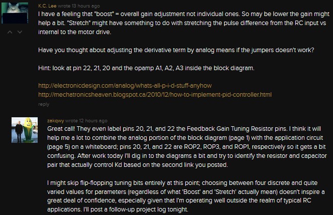
It's an excellent comment from someone who wants to help me learn more about analog circuits. Unfortunately, K.C. Lee posted a previous comment that was a bit less Socratic; I saw the previous (and subsequently deleted) comment show up on my feed this morning. Full disclosure, people: I copied the answer into an email, sent it to myself, and haven't looked at it since. I want to explore this circuit on my own--I've never done much with op-amps--but it will be nice to check my answer when I'm done. I hope you trust that I've done that.
First, as I suggest in my comments above, I used my whiteboard to combine two items from the FR6461 datasheet: the chip's internal block diagram and the application circuit. I cut off a decent amount of circuitry from both sides, but I think I've captured the relevant stuff (apologies as always for the shoddy whiteboard picture quality):
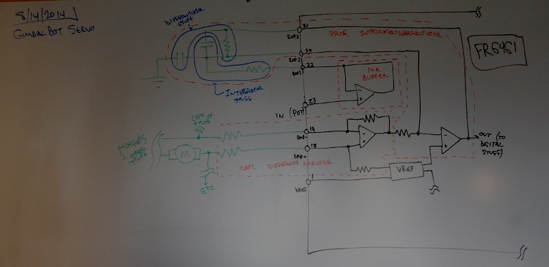
A few things to highlight on the diagram:
- Black symbols and lines are from the internal FR6461 block diagram; green symbols and lines are from the application circuit.
- Like I said, I'm pretty new to op-amps; I've seen Dave's great intro video (amongst a few others on the same subject) and played around with 741s as audio preamps as a kid, but I've never gotten in to any sort of depth with the things. I read through a great report (*.pdf warning) I found online from UPRM, and tried to identify different op-amp circuits from the diagram. They are as follows:
- Mr. Buffer. He handles the incoming signal from the potentiometer, which returns an instantaneous measurement of the current servo shaft position, and presumably scales it to a value usable by the rest of the circuitry.
- Prof. Integrator-Differentiator. At least, that's what it looks like, based on the Integrator and Differentiator sections of the report linked above. I used blue marker to highlight the resistor and capacitor associated with each function.
- Capt. Differential Amplifier. His inputs are connected to quite a few items, but from what I can tell he's looking to see what the entire system is telling the servo to do; not where it is, but what direction it's going and how fast it's trying to get there. Presumably, looking at the differential across the motor drive circuitry will output a signal proportional to speed and direction, which is then fed in to Prof. Integrator-Differentiator. Here's the concern I have with this: why is the furthest-left capacitor grounded? Is it just a filtering cap to deal with noise? Do the Integrator and Differentiator functions actually share the second capacitor? That seems like it would make a bit more sense; in the second document K.E. Lee linked the second design (series PID algorithm) seems to follow the right side...
- Okay, back up for a second. I can't line up the circuit with any of the examples shown there; the resistor and capacitor staying in parallel doesn't seem to follow, given that they are connected to the output of the rightmost op-amp. I can only find op-amp sample circuits where the capacitor is used in series with a resistor in the feedback line, not parallel.
- Time to do a bit more reading.
- Okay, midway through some reading. It looks like the center capacitor--the one in parallel with the resistor--is there to prevent local amplifier oscillation. I'm marking that on my board. The resistor and capacitor I labeled are part of the differentiator circuit; still not clear on why the capacitor is grounded though. More reading!
So I'm still not entirely clear on how the circuit works, but I'd like to understand how the thing is actually wired. As such, I'm going to do two things; first, I'll draw a blown-up picture of the PCB; second, I'll try to derive the schematic for the above circuit from that drawing, and related it to the FR6461 block diagram (probably erasing the green stuff in the process); third, I'll redraw the entire thing as a flat schematic, pulling the resistors and capacitors into better positions with respect to the various op-amps. I keep getting confused looking at the board, since the FR6461 pin positions force me to change schematic wire routing.
Comments are welcome. I'm going to stop this log now but will hopefully post another tonight with an as-built schematic of the analog portion of the servo board, integrated with the FR6461 block diagram.
Discussions
Become a Hackaday.io Member
Create an account to leave a comment. Already have an account? Log In.