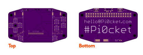
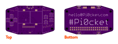
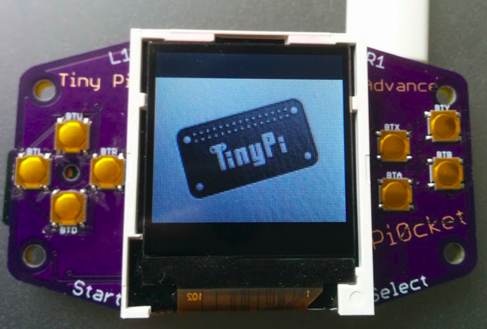
• always learning!!

    moosepr04/20/2018 at 22:19 0 comments

    So most of the drive behind this project is to learn and grow from the original TinyPi. The TinyPi method of mounding the Pi onto the back of the PCB saves space, however can be a little tricky to get the solder to pass through and make a good connection. There is also the screen ribbon that can be a bit of a challenge.

    The screen can easily be solved. There are many screens that are designed to connect to a zif socket. This will make installing the screen a trivial task of inserting a ribbon and swinging a lever.

    Attaching the Pi is more of a challenge!! 

    The 'normal' method of attaching the Pi would be to use header pins. The problem with this is that the space being so critical, the front face of the PCB needs to be kept clear for buttons, so that is a limiting factor. 

    The next best option is to use SMD header pins, which could be pre-soldered during the rest of the assembly process. The problem with the SMD header pins is the larger then standard footprint needed would require more board area!!

    While searching about I managed to find some surface mounted pogo pins. these would have an additional benefit of making the Pi attachment solder free!! this means that anyone could build the device, and make it more accessible to the masses. The downside of the pogo pins, is the additional distance between the boards. This could be used as an advantage, and the battery can be placed between the boards. So i bought some pins from everyone's favourite Chinese supply website, and did a test

    now these pins are crazy tiny!! so I eventually managed to get those pins attached to the solder pads on the test boards i had

    so with some screws and spacers, the pi can be clamped onto the back of the boards and connect to the PCB.

    Maybe this could work.....

  • spin it!

    moosepr04/13/2018 at 20:43 1 comment

    so having all the right angle buttons on the back with the Pi, had its issues. Thankfully not all of the buttons technically need to be mounted on the back. The Start and Select buttons can be sneaked down at the bottom left and right of the screen, which means we can spin the Pi round and have clear ports!!. At the same time, i thought i would try some smaller Piezo transducers, which could flank the screen rather than being behind the screen. All this will help reduce thickness and make a better TinyPi :)

    onwards.......

  • Try before you buy!!

    moosepr03/26/2018 at 22:00 4 comments

    The board design was pretty much nailed, I just added a touch more design flourish and then it was done

    The boards were made by @oshpark and as usual came back flawless

    so i fired up the soldering iron, and while i was waiting, just had a look at how it all fitted together, and oh no!!

    I did not check where those ports were!! As this is just an early prototype i carried on and made it work. Trimmed some of the usb socket metal and things just about went together.

    although nobody is using that usb port!!

    It just goes to show that you should always check your designs before you splash the cash!! At lest it went together ok ;)

  • Leaning curve

    moosepr03/24/2018 at 09:51 4 comments

    I wanted to build on the work of TinyPi, but also improve upon it. The main goal of the original project was to go as small as possible. While this does give targets and bragging rights a plenty, it also has an impact on the usability of the device. Because the pi sits flush against the back of the pcb, and the screen takes a massive hunk of space, there is then minimal space for the controls.

    Moving to the landscape layout, but keeping the screen portrait (they look terrible any other way) meant that there was a touch more space to play with. This space meant that the power switch and the battery connections could be moved to get rid of the wires that poke out on the original design.

    While I was making changes, I decided to ditch the 5 way navigation switch in favour of 4 actual buttons, allowing the d-pad to be created. While searching for low actuation force buttons, I found some which looked very much like the buttons used in a Gameboy advance SP. These seemed ideal for my needs, affordable, small, easy to solder, and if it's good enough for Nintendo, then I'm sold!

    In the same area, I spotted some right angle buttons that also look very similar to Nintendo ones, and decided I could monopolize on the extra bit of PCB available from the screen rotation, to add 'shoulder' buttons. While I was at it, the start and select buttons could be moved out of the way too.

    So the new board was designed, and sent off to oshpark for making