 The Virtual Traveller
-
Spot the Difference
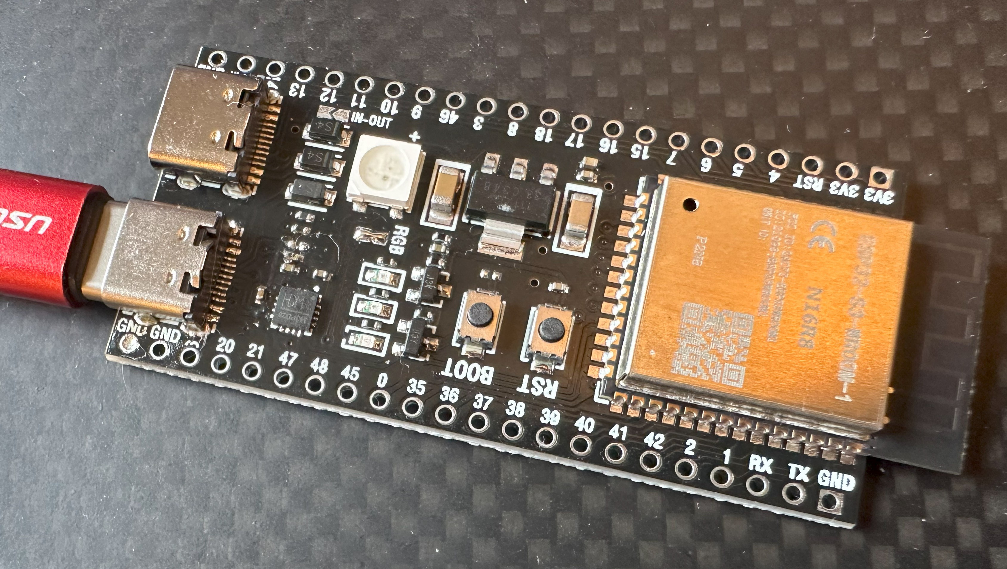
04/07/2024 at 09:05 • 0 commentsCan you tell the difference between these two pictures?
![]()
![]()
The astute among you will realize that the board works when the USB-C is plugged in one-way and not the other.
I bought this ESP32-S3 board as part of a batch and it just wasn't working like the others. Firstly, I discovered that the RGB link needs to be joined for the on-board WS2811 pixel to work. But more important was finding the cause of the fault.
My first, and incorrect assumption was to replace the USB-C socket. Which I did without anything coming to any harm, but it didn't fix the issue. What I'd failed to catch was the obvious: cable orientation behaviour is based on the CC1/CC2 lines. ALWAYS check those first.
Sure enough, my old friend the 5k1 was shorted, but only on CC1. So I removed it, but because I didn't have any 5k1 "in-stock", I then moved the 5k1 resistor from CC2 to CC1; which is why if you're really observant you'll see a missing resistor on the board. The CC1 orientation then powered the board without issue, and confirmed that the shorted 5k1 was the only problem.
So - after a few days I'll have the 0403 5k1 SMD resistor I need to make this board fully working again. My advice to board debugging? Never discount the most obvious things before leaping to the wrong conclusions - if I'd done that I'd have saved myself the dicey swapping of the USB-C socket with a hot air gun.
-
Never What You Think
04/07/2024 at 08:31 • 0 commentsSo I bought an ESP-1, ESP-12, ESP32 programming jig from AliExpress. They look like this:
![]()
It arrived what I thought was DoA. I was unable to get any life out of it. So, as they're cheap, I just ordered another. A second one arrived also DoA, which then got me thinking, what had happened?
After extensive checking of the USB-C connector, I eventually realized there were no 5k1 ground pulldown resistors on the USB-C CC1/CC2 lines. More so, CC1/CC2 weren't even connected beyond their pad.
Once I knew this, I knew what to do to make the board "work". By taking a USB-A to USB-C adapter, and building a frakencable to go USB-C to USB-C VIA USB-A I was able to power the board and communicate with it.
Win.
So what happened here? Well as far as I can work out, old designs in Chinese factories are just getting USB-C sockets slapped on rather than microUSB ones. The result is no regard of the USB-C protocol and its electrical requirements.
Once you know what's happened, everything falls into place. I could add CC1/CC2 5k1 ground wires or I could continue to use a frakencable. But all I can say for sure is, when debugging a problem, it's never what you think.
This user joined on 04/07/2024.


 makeTVee
 Samuk
Samuk MartMet
 kelvinA
 Mrinnovative
 Hpsaturn
 Rahul Khanna
 Tim van Iersel
 finallyfunctional
 Andrew Woodbridge
 selena1995
 James Fossey
 suikale
 Ward Almasarani
 Udara Kumarasena