 Andrew Starr
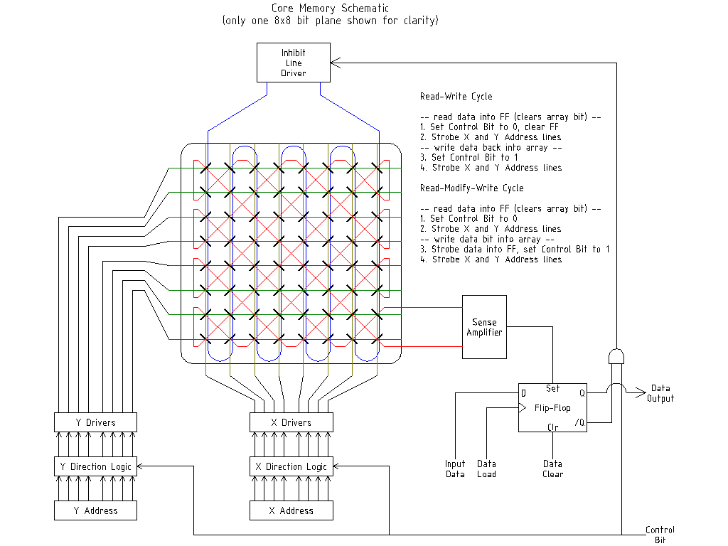
0%
0%
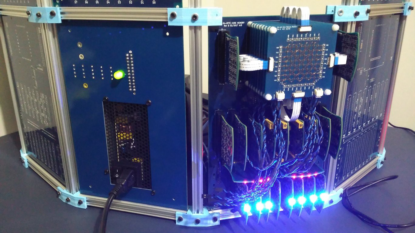
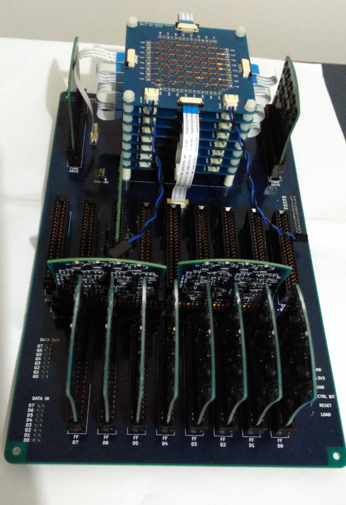
Ferrite Core Memory Module
A sub-project of the ED-64 Computer to document the development of a 64-byte ferrite core memory module
Become a Hackaday.io member
Already have an account? Log in.
Just one more thing
To make the experience fit your profile, pick a username and tell us what interests you.
Pick an awesome username
hackaday.io/
Your profile's URL: hackaday.io/username. Max 25 alphanumeric characters.
Pick a few interests
Projects that share your interests
People that share your interests


 Artem Kashkanov
 Nigel
Nigel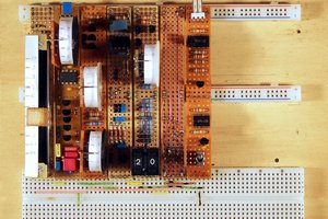
 Rainer Glaschick
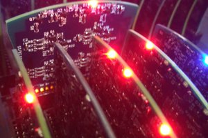
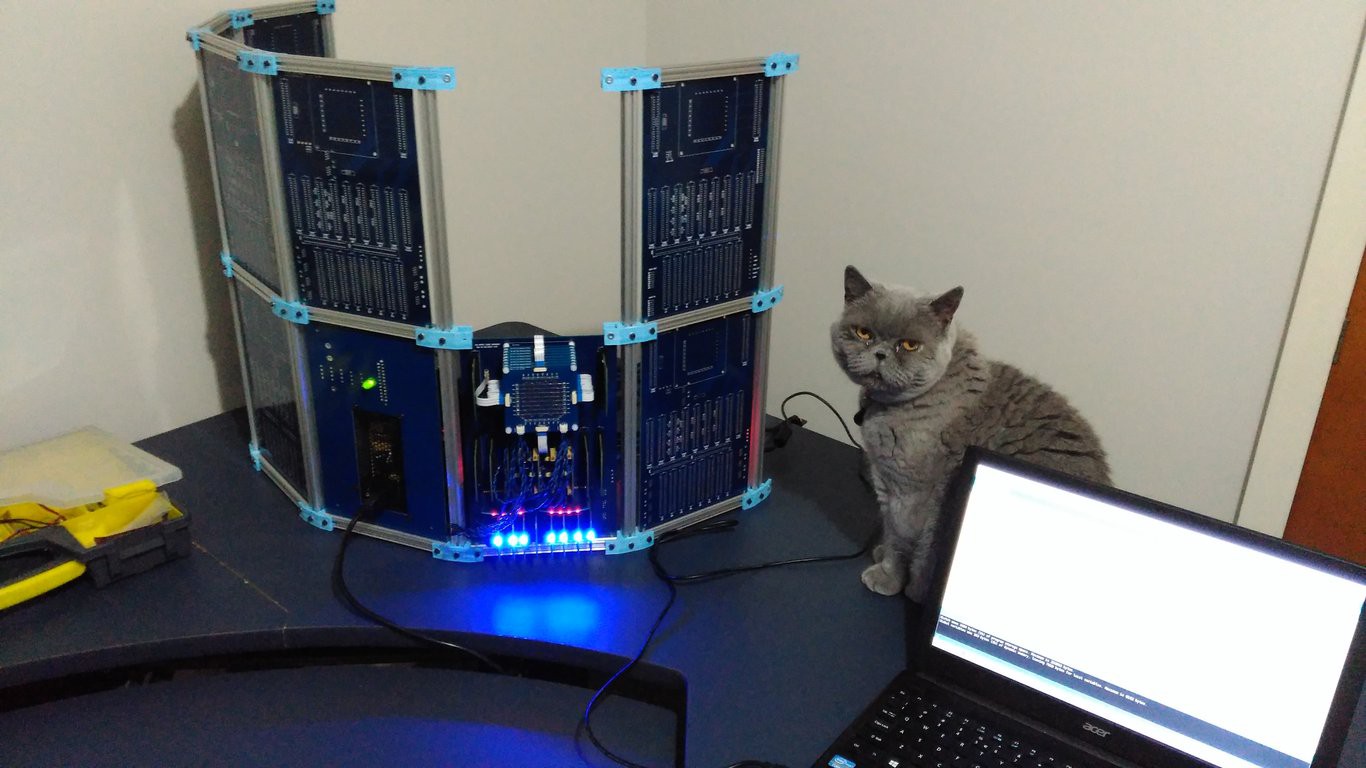
Great project! I like the nod to industrial design with some simple curves. Nice touch.