 davedarko
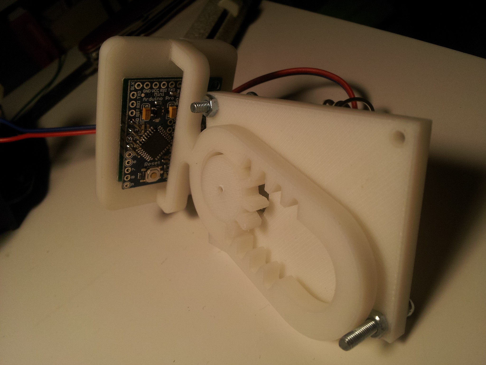
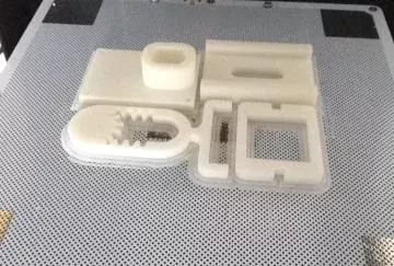
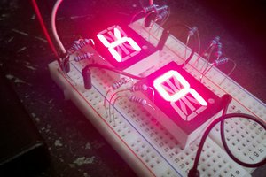
The plan is to build a persistence-of-vision display, where a small Matrix of 8x8 LEDs will be moved around by a motor on one axis. Starting small I will take a 32mm x 32mm LED matrix. I have to figure out a rough box where the movement is exploitable and get some fancy software hacked together. I'm thinking about 4 rods, where the led board can slide on, with a copper pipe soldered to the boards for alignment. There will be a lot of forces going on and I will have to deal with electrostatics and heating problems on the moving parts, I guess.
Syncing the display to the movement will be another thing to solve, but seems manageable for an arduino.
So if it will work, I'm going to upgrade it to a 8x8x8 6cm rgb matrix, but for now let's start small...


 Kenneth Zaborny
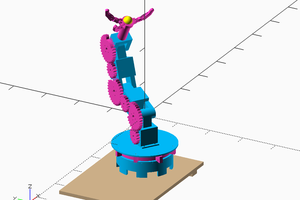
 Les Hall
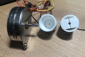
 kmatch98
One way to separate your POV display from the electronics and prevent them from being shaken to pieces is to have the moving display surface be a screen that displays a projected image onto the moving screen. Maybe use a mirror surface and mount it 45 degrees to a display screen that has a video playing that is synced to the motion of the mirror. The viewer would be looking 90 degrees to the video display (45 degrees to the moving mirror). The video would give continuous display synced to smooth continuous motion.
If you want to use an LED display that actually moves back and forth, you could eliminate the wires by having separate controllers for the moving screen and the stationary motor and sync them using WYFI transmission. If you want to eliminate a battery on the moving display then add a coil that passes by a stationary battery and generate the screen system power from the movement. The signal generated by the coil passing the magnet could also generate your pulse for establishing position for the image sync.