Tentatively, we'll be using the Xilinx Artix-7 XC7A35T in the CSG325 package as the heart of ROPS. The 35T is a mid-range Artix part, and the CSG325 package bonds out the all-important GTP transceivers so that we can use PCI-e to connect to the host computer.
The sensors we plan to use are the ST LSM9DS1 IMU, ST LPS25HW barometer, and the uBlox NEO-M8T GPS.
There will be back-panel IO for connections to third party hardware such as motor controllers and additional sensors, but we haven't nailed down any details yet. Very little of the FPGA's IO is currently spoken for, so there is a lot of flexibility here. It's also likely that additional IO will be available on mezzanine or flex cable connectors inside the host computer's case.


 Rue Mohr
 Mark VandeWettering
 Dave Collins
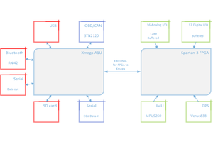
 Nigel
Nigel