 Bharbour
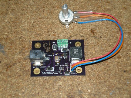
This project is using a couple of the OSRAM Oslon warm white 3000K LEDs. Initial experiments with these LEDs indicates that they will provide more than adequate light for an assembly microscope. I built up a board to go behind a 50 mm reflector, but that reflector seemed more like it was designed for a flash light. The second rev board was designed around the reflector shown in the picture. This has a good tight beam and uniform distribution. A heat sink was designed to be machined out of 1.5" aluminum bar stock that would mount on the end of a 20" microphone gooseneck to allow the user to direct the lights where they want them.
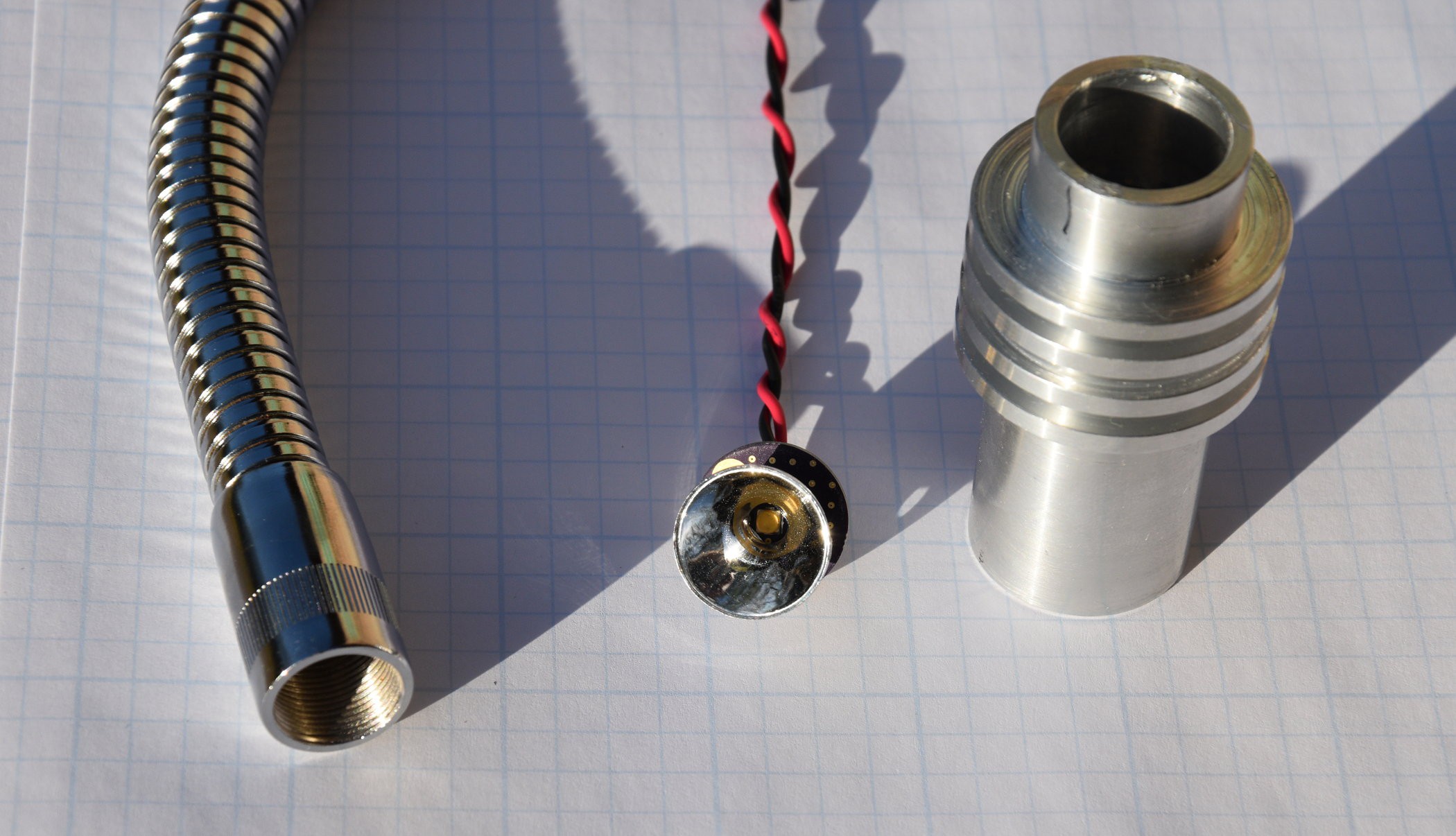
The LED mounting board has lots of copper on both sides, and is stitched with vias to get the heat off the front side (LED side) and into the heat sink that will be bolted to the back side of the board. The LED is rated at up to 1.8A continuous, but initial tests look like 300mA will be sufficient.
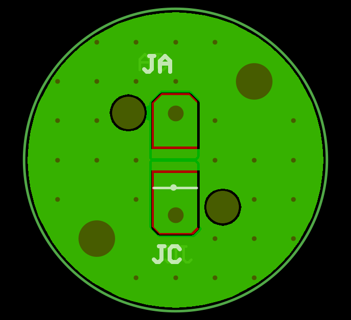
I spent an entertaining day simulating a design for a hysteretic constant current power supply, but when the design was complete, the parts cost was going to be about $15. Digging around on Digi-key, they had 2A LED driver chips for $0.65. I laid out a 2 layer PCB for the driver chip.


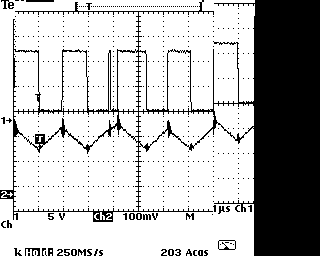
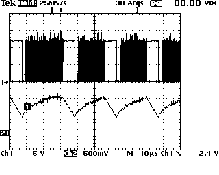
 and Inductor Current (ch2) at 135mA LED Current.")
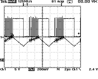
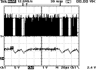
 and Inductor Current (ch2) at 375mA LED current.")


 Christoph Tack
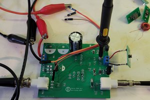
 Kevin Kessler
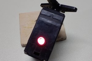
 Ted Yapo
 Glenn.Kubota (gee.k)