 Craig Watson
This project is born out of necessity, as part of my microfluidics control system. For that project, I need precise air pressure levels, and a way to set them using a microcontroller.
I had bought some commercial pressure regulators, but these turned out to be a disappointment. They are imprecise (especially at low pressures), leak a lot of air, and have a tendency to report incorrect pressures. This won't work for a solution that has to be reliable enough to run for days at a time with little to no supervision, so I decided to make my own pressure regulators.
As an added bonus, it will cost less than half the price of new, commercial regulators. I hope it can also be a useful contribution to the community here, for anyone working on soft robotics, microfluidics, or anything pneumatic.
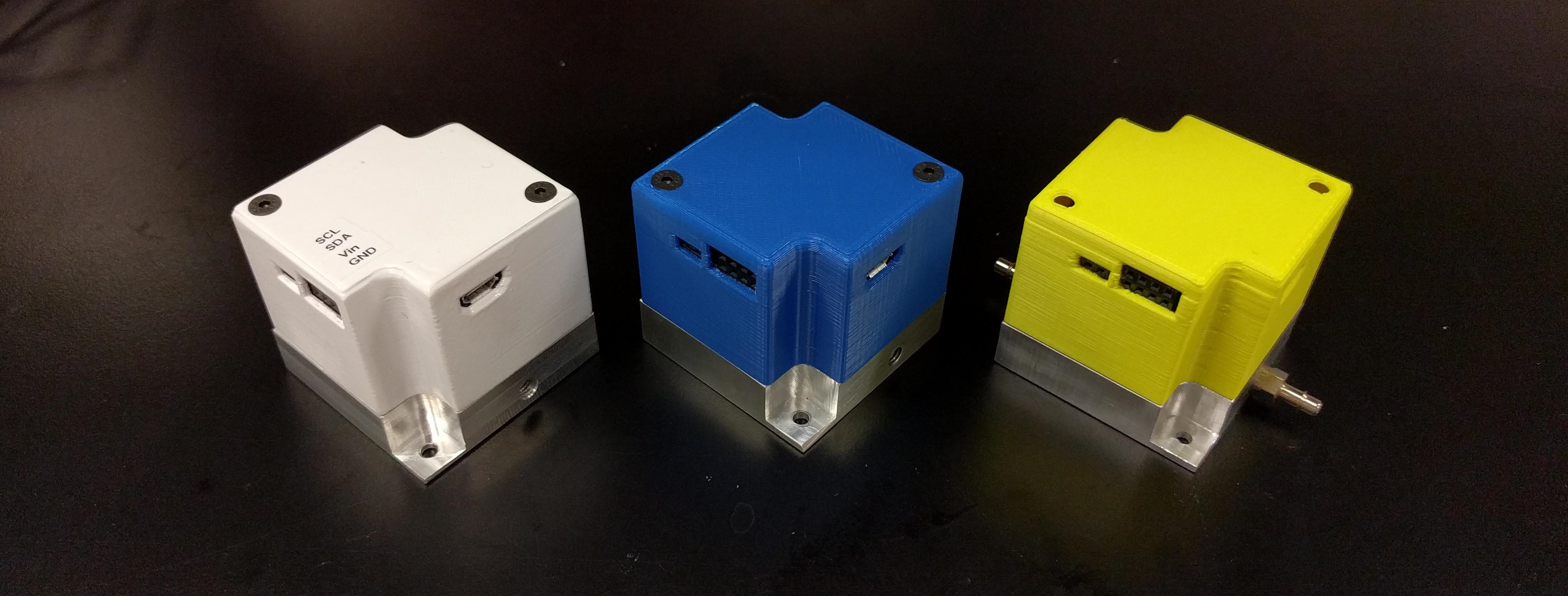
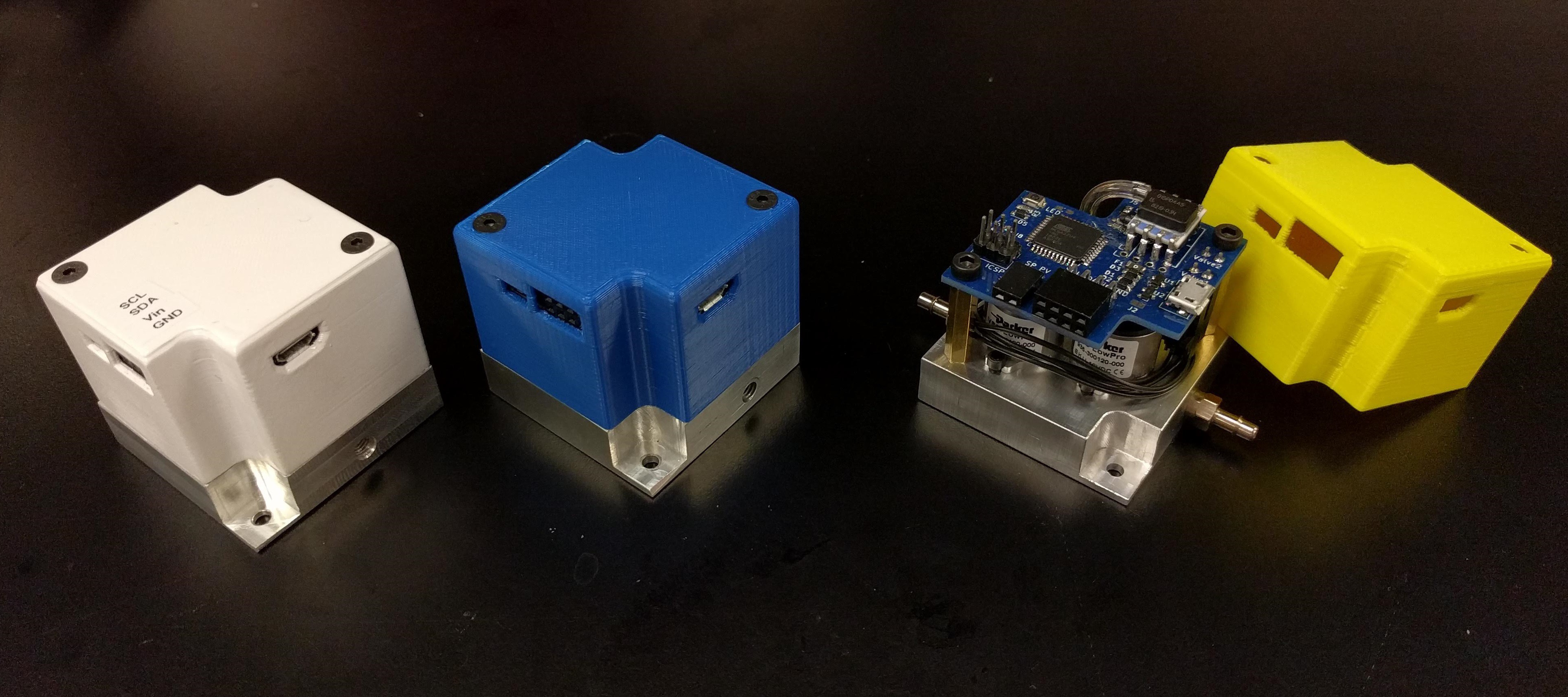
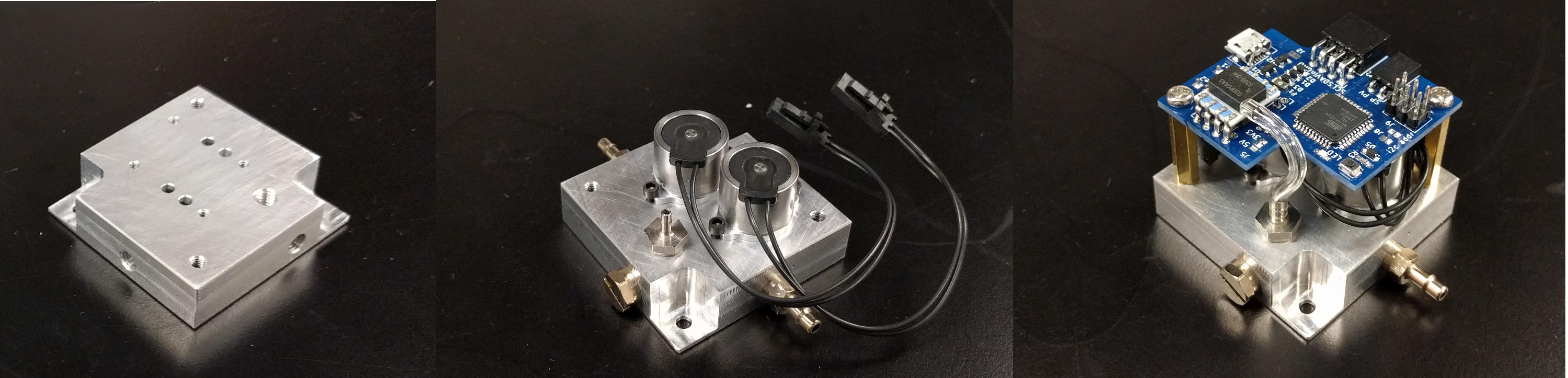
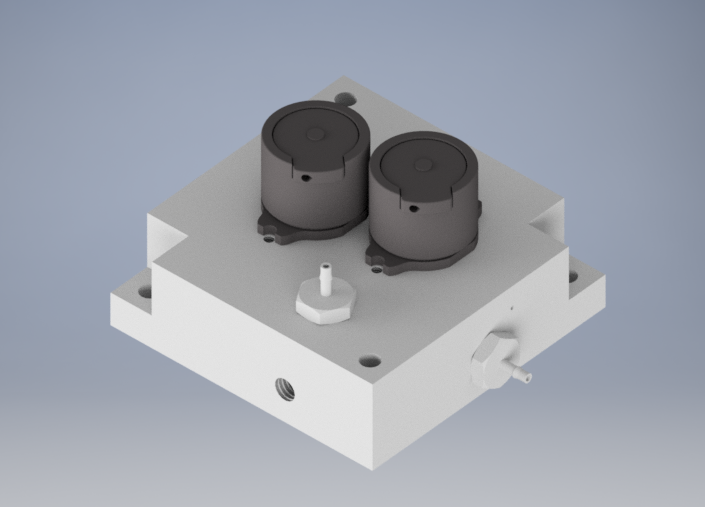
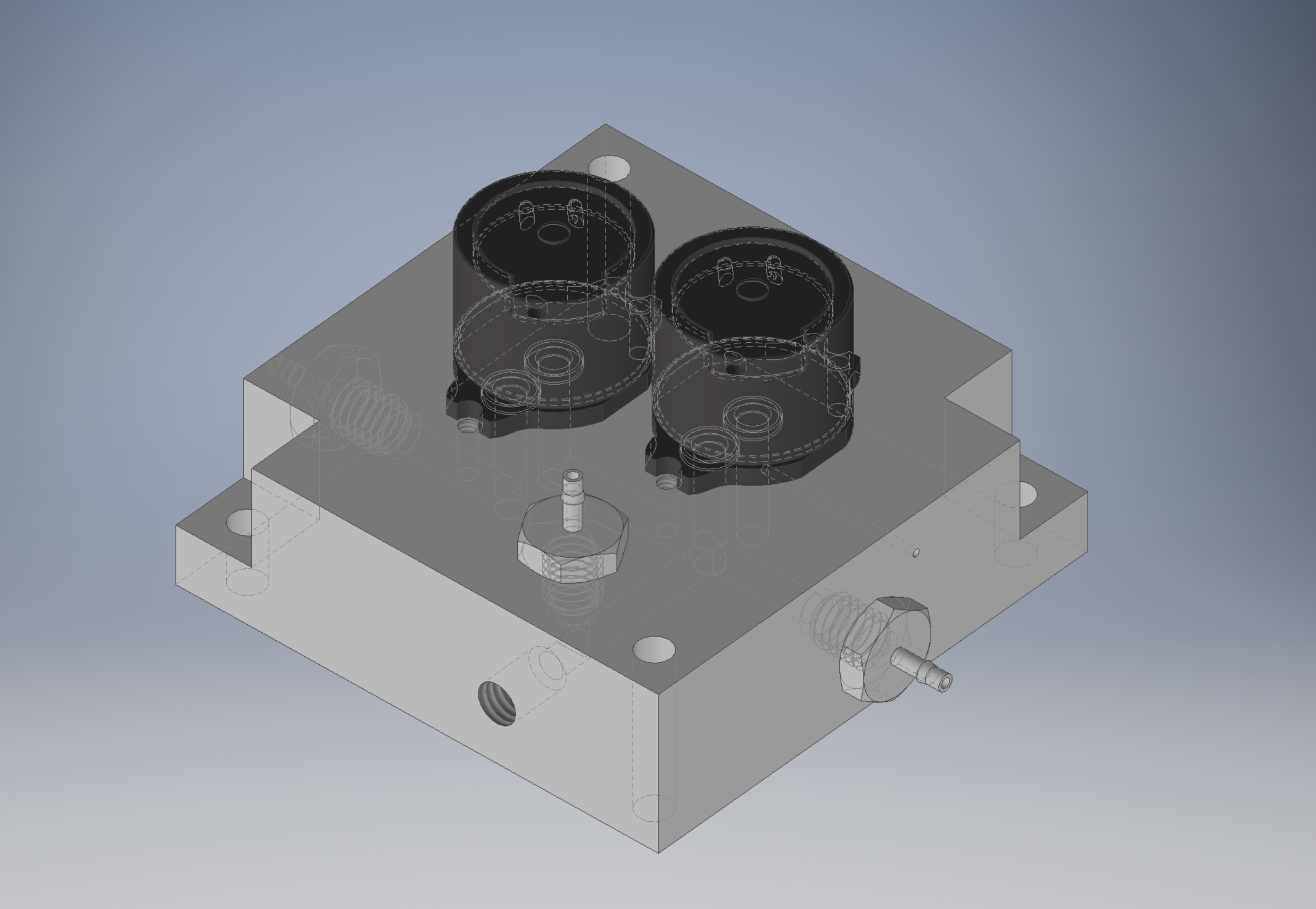
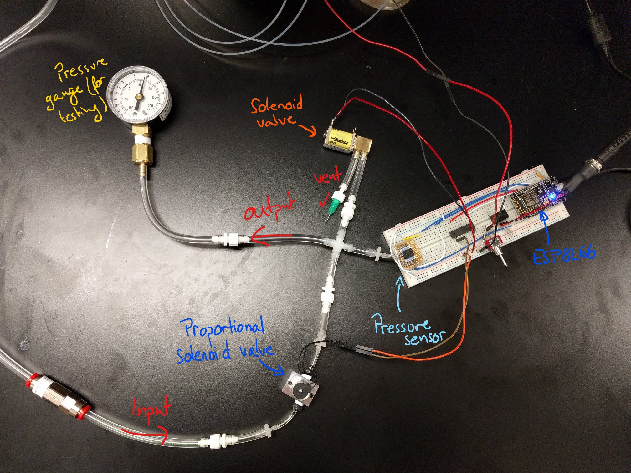
The pressure regulator is a roughly-4.5cm cube, with various mounting options for easy integration into other projects. USB, i2c and analog interfaces make it possible to set the desired pressure and read the current value from virtually any other device.
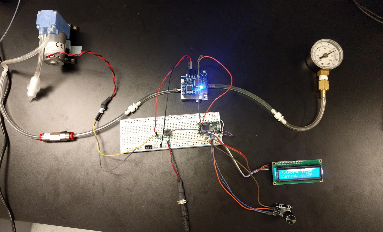
It is especially suited to applications with low air requirements and limited supply (such as a portable device using an on-board pump or a small gas cylinder), but should be able to handle high flow rates equally well.


 Amitabh Shrivastava
 Tim Rightnour
 ventosus
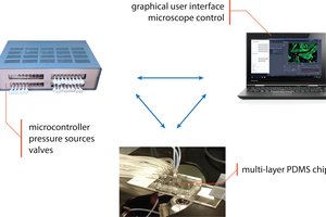
Strange question.
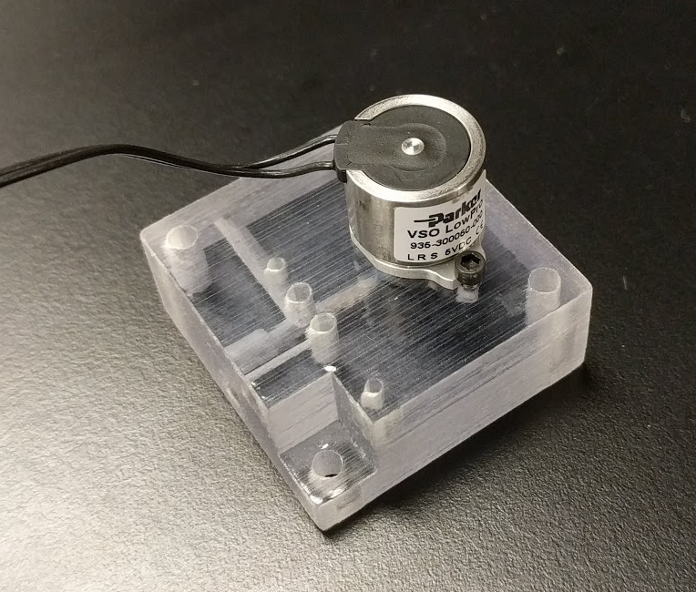
Those fittings. Nickle plated, or all aluminum? Also, 1/8 ID tubing?
Trying to figure out where to source them, but am not having much luck.