Christoph Tack
-
Dimming the array
06/23/2018 at 19:17 • 0 commentsThe advantage of using the 74HC595 over the MAX7219 and the HT16K33 is that it has an /OE (output enable) pin. It can easily be used to dim the LEDs from 0 to 100% in as much steps as you like. Unlike the MAX7219 which is frequently used on LED array modules. That IC only allows for 4bit dimming control.
In the video /OE is connected to a 16bit PWM port of the STM32 Nucleo (i.e. pin 6).
-
First test
06/23/2018 at 14:11 • 0 commentsPCB Assembly
There's not much to report here. All parts fit correctly. I suspect ALLPCB from drilling the holes for the PCB studs a bit too large.
Pin 1 of the pin headers was not marked in the silkscreen of the PCB. This will be fixed in the next revision.
Electronics
Before connecting power, all connections should be checked. I felt confident enough to skip this step. The schematics don't contain any new circuitry to me.
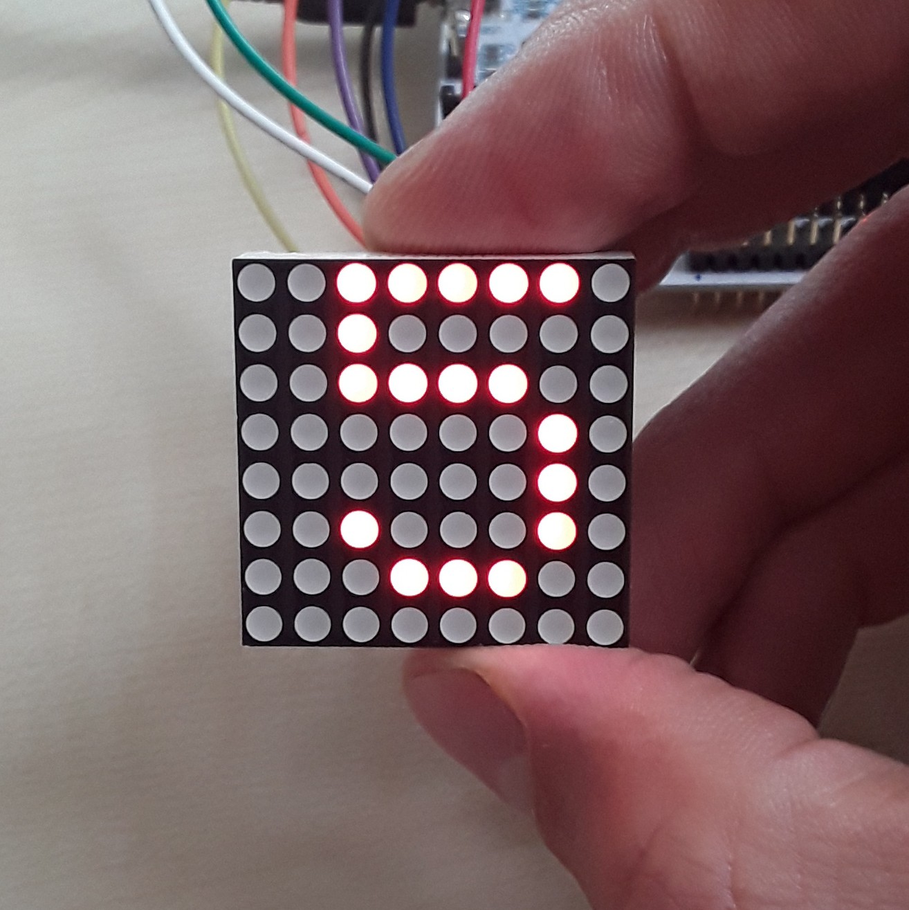
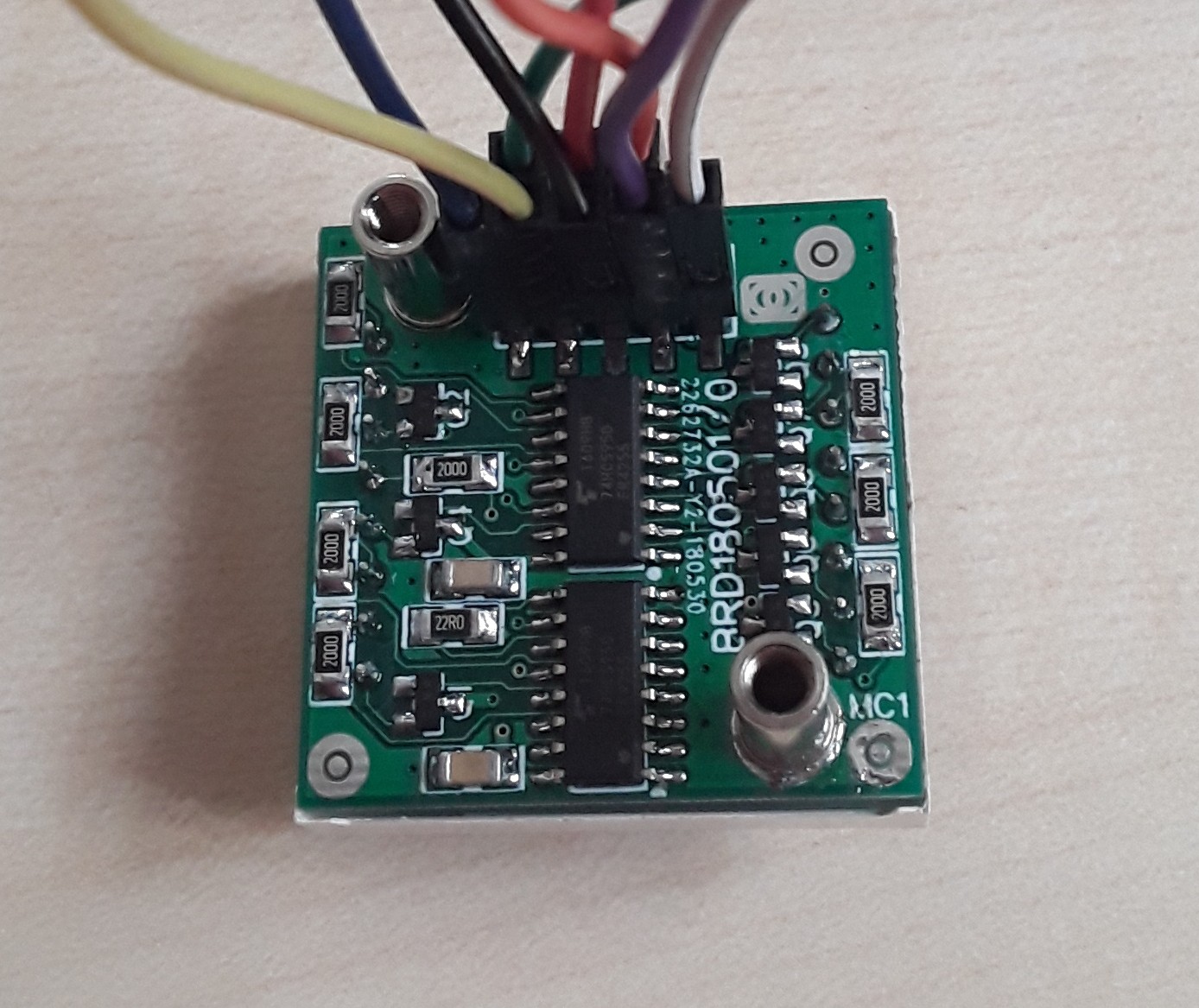
Unicorn! Revision 0 is fully functional.
![]()
![]()
Firmware
The Adafruit GFX is quite nice. This will be used to provide high level functionality for drawing lines, character sets etc... I only need to write a low level driver that can color a pixel at the desired coordinate.
It didn't take too long to get this working.
Next thing is adding dimming functionality.
-
Interconnection
05/10/2018 at 20:02 • 0 commentsBrowsing on LCSC learned me that the cheapest board to board connection is a through hole header/socket connection.
Pitch
2.54mm is the most widely used and easy to solder
Number of contacts
2x5 & 2&6 pin configuration get you the most bang for the buck when taking into account the cost of the mated connection, i.e. male+female part. They only cost $0.01 more than the 1x5 or 1x6 configurations. The benefit of having extra pins is also having extra ground return paths. This reduces the HF-current loops of the SPI communication.
PCB Mounting
Through hole components are cheaper, but require an extra PCB process: wave soldering.
SMT components are more expensive, but can be reflow soldered with the other SMT parts. The PCB supports both connector types.
Mating height
This might be a bit of a bummer if you really want low profile. The male header requires 2.5mm height, while the female socket puts 8.5mm on top of that. This amounts to a 11mm inter-PCB distance.
Mechanical fixation
The LED PCB must be supported on both sides to keep it stable. Adding a few additional header/socket connectors on the corners might do the trick.
Another option was to use plastic self retaining spacers. Wuerth has these in their product line. These require a free height of 1.9mm under the LED matrix.
Instead I opted for SMT studs. They can be reflow soldered with the rest of the SMT components. These studs have an internal M3-thread, so they provide for an firm screw connection to the base board. They're electrically conductive, so can be used to return ground current, a benefit to keep EMI under control.
-
Display Driver
05/10/2018 at 19:34 • 0 commentsThe driver should have SPI or I²C interface and allow dimming.
SPI
- MAX7219 : LCSC.com : €2.07 (Digikey >€7)
- has an internal 8x8bit RAM buffer
- 74HC595 + 74HC138: 8 outputs, cheap, standard part, PWM-dimming using /OE-pin, Digikey €0.33/pce. This has the disadvantage that next to SPI, extra control lines for the 74HC138 are required.
- 2x 74HC595 : One 74HC595 as row controller (only one row should be on at a time). The other 74HC595 is used as column controller. Using the same device twice reduces BoM length.
- no RAM buffer, so each row must be written at least 25 times per second to keep persistence of vision.
- TLC5925 | STP16CPC26 | CAT4016 | MAX6969: 16 outputs, integrated current source, Digikey €1/pce. This might be useful for dual color LED matrices. Here only 8 outputs are needed.
I²C
- PCA9685 : LED driver, Digikey €1.80/pce, hard to solder by hand : TSSOP
- HT16K33 : popular on led matrices, LCSC.com : €0.33, not available on Digikey.
To avoid that the 74HC595 has to source the current for the LED array, transistors will be used, as switches. Three transistor types could be used : PNP, NPN and PMOS:
- PNP would require base transistors. There's little room for those.
- PMOS is more expensive than NPN.
- NPN is used here as a switchable diode. There's at least 0.7V over the NPN. In this application it doesn't matter. It helps for spreading heat over more components, avoiding hotspots.
- MAX7219 : LCSC.com : €2.07 (Digikey >€7)
Tileable 8x8 LED matrix
1.0" LED Dot Matrix 8X8 Cascadable Module with SPI interface