 Rudolph
-
1Acquire the transmitter parts
Step one has some options. You can acquire an old Tx from the thrift store and either use it as the basis for your Tx, or pilfer its parts (e.g. the gimbals) to put into some other housing (another Tx body or a custom one). Or you can just acquire some gimbals to build into a custom box. However you see fit.
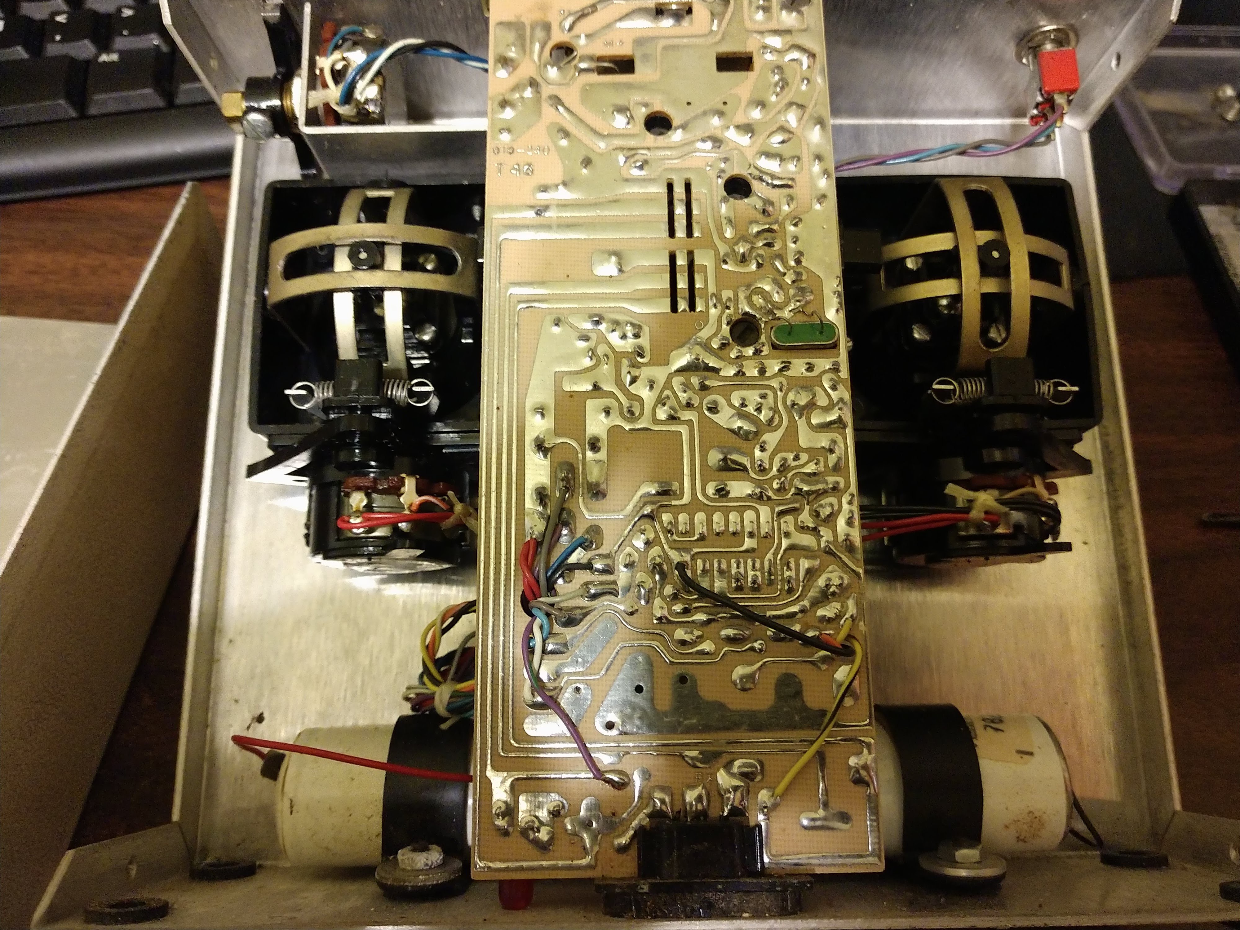
If you're going with an old Tx, open it up and clean the blech out of it. Make sure you know how parts go back together if you intend to reuse it. I learned the hard way (had to ask a forum for help) that the sockets for the sticks in my Tower Hobbies (made by Kraft, btw) do not get screwed down all the way (even though the radio came with them that way).
![]()
I had to desolder the antenna mount and the battery/RF meter from the PCB
![]()
I cut the bundles of wires about an inch off the pcb, so if I ever want to put things back I can match up wire colors easily.
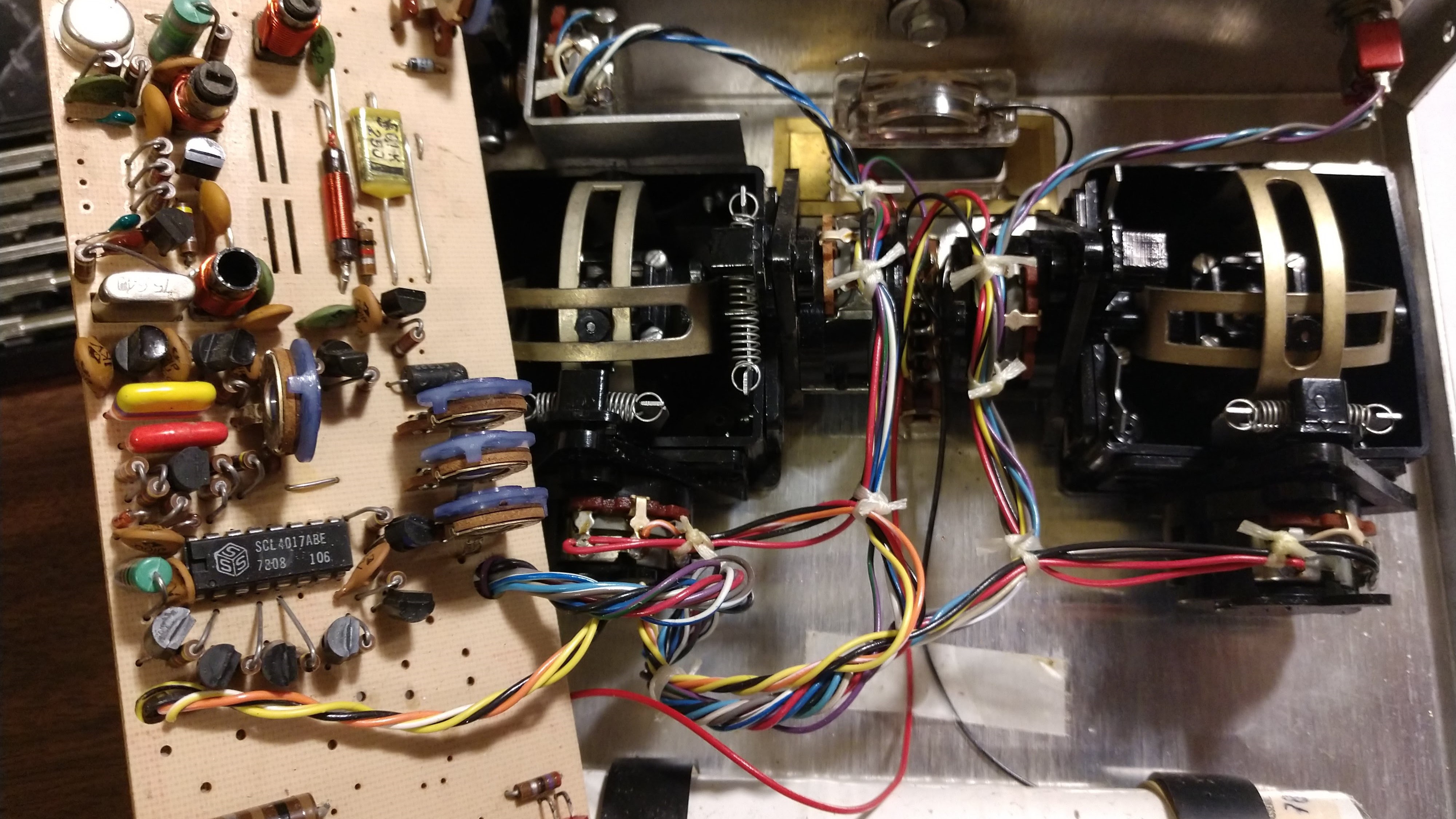
Whether you're putting the gimbals back in the donor, or just taking them to put into another housing, take this opportunity to clean the pots, check the solder joints, and test the pots with your multimeter. A classy vintage radio look is useless if the sticks don't work.
-
2Prepare the electronics
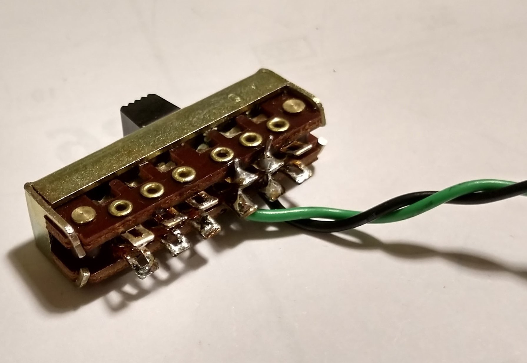
This project uses a Teensy 3.2 on top of a breakout board which makes servo-style connections easier. Follow the instructions that came with your breakout board to assemble, including cutting the trace between VIN and VUSB. However, do not solder in the switch in step 3, instead opt for the 3 pin header. That way you can solder a couple wires to the transmitter's power switch and use it to switch the transmitter on and off. For good measure I also added a couple 100µF capacitors to the 3.3V power rails.
![]()
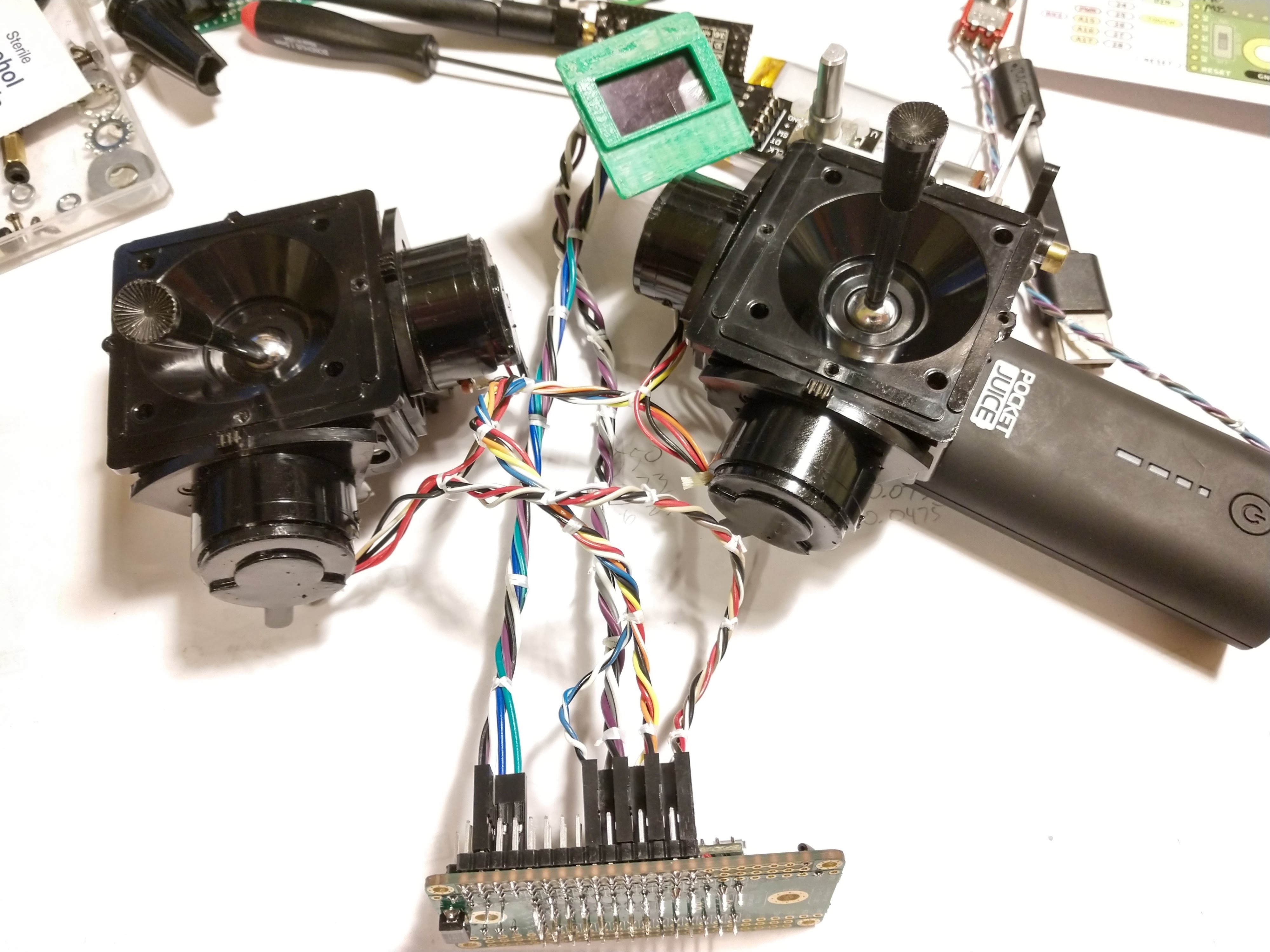
If, like me, you had to cut the gimbals' wires off the Tx pcb you'll need to decide how you want to connect them to your Teensy. I was out of connectors so I grabbed a "Dupont Connector" kit from Amazon to put connectors on the wires. (No, I will not be using affiliate links anywhere in this project.)
![]()
This was the part where I fell deeper and deeper down the Google rabbit hole looking into cable lacing.
Once your gimbals are wired up and connected to your microcontroller you'll want to find out just what their ranges are. Grab the "rudRemoteStickFinder" sketch from the repository, set the pin definitions, and load it onto your Teensy. This just simply spits out the analog values of the pots to Serial. Make note of the minimum and maximum values of each stick's X and Y travel.
-
3Decide on, and perform, any necessary hardware modifications
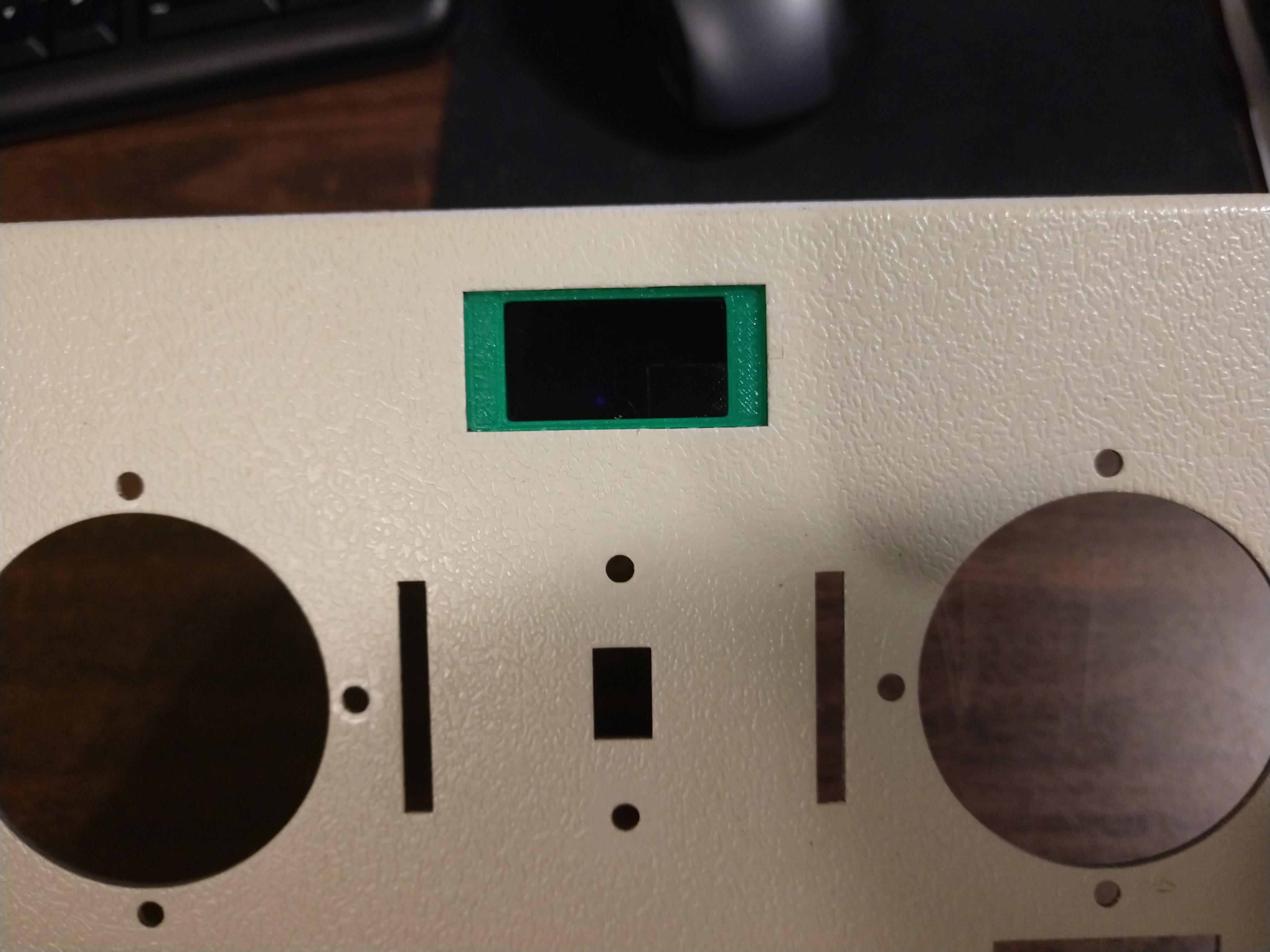
For the time being I've decided to forego a bunch of hardware modifications. Because this controller is intended to motivate some robotic things, and the Teensy has a preponderance of I/O, I will likely end up adding more pots and switches down the line. But for now I decided to just go with a little OLED display, and a rotary encoder for navigating the configuration menus displayed on said OLED.
![]()
It was with a heavy heart that I decided to put the OLED in place of that beautiful analog RF/battery meter.
If you have the same 0.96" OLED as me, and you have a Tower Hobbies (or Kraft) transmitter like mine, you can grab the screen-to-hole adapter I bodged together.
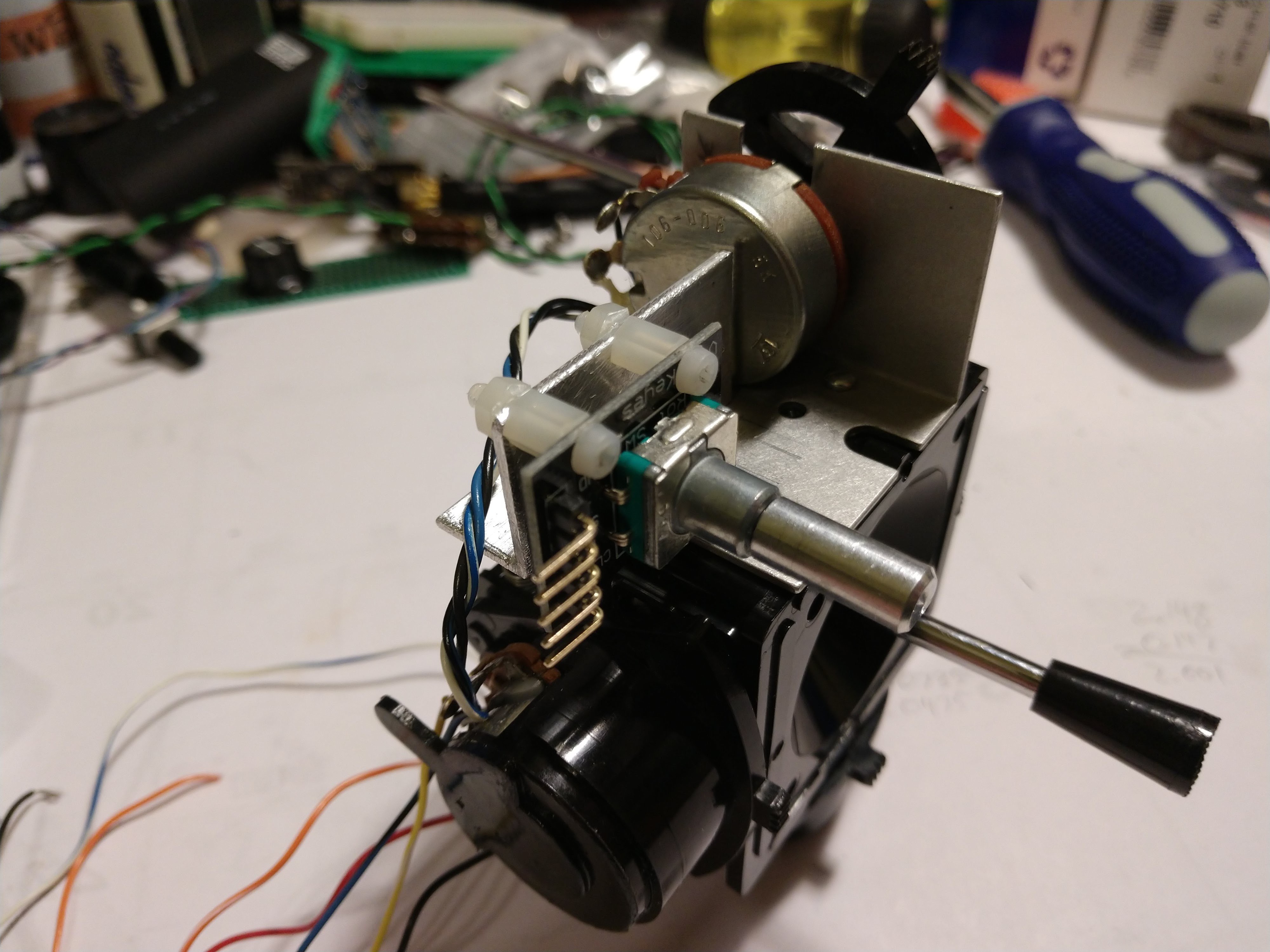
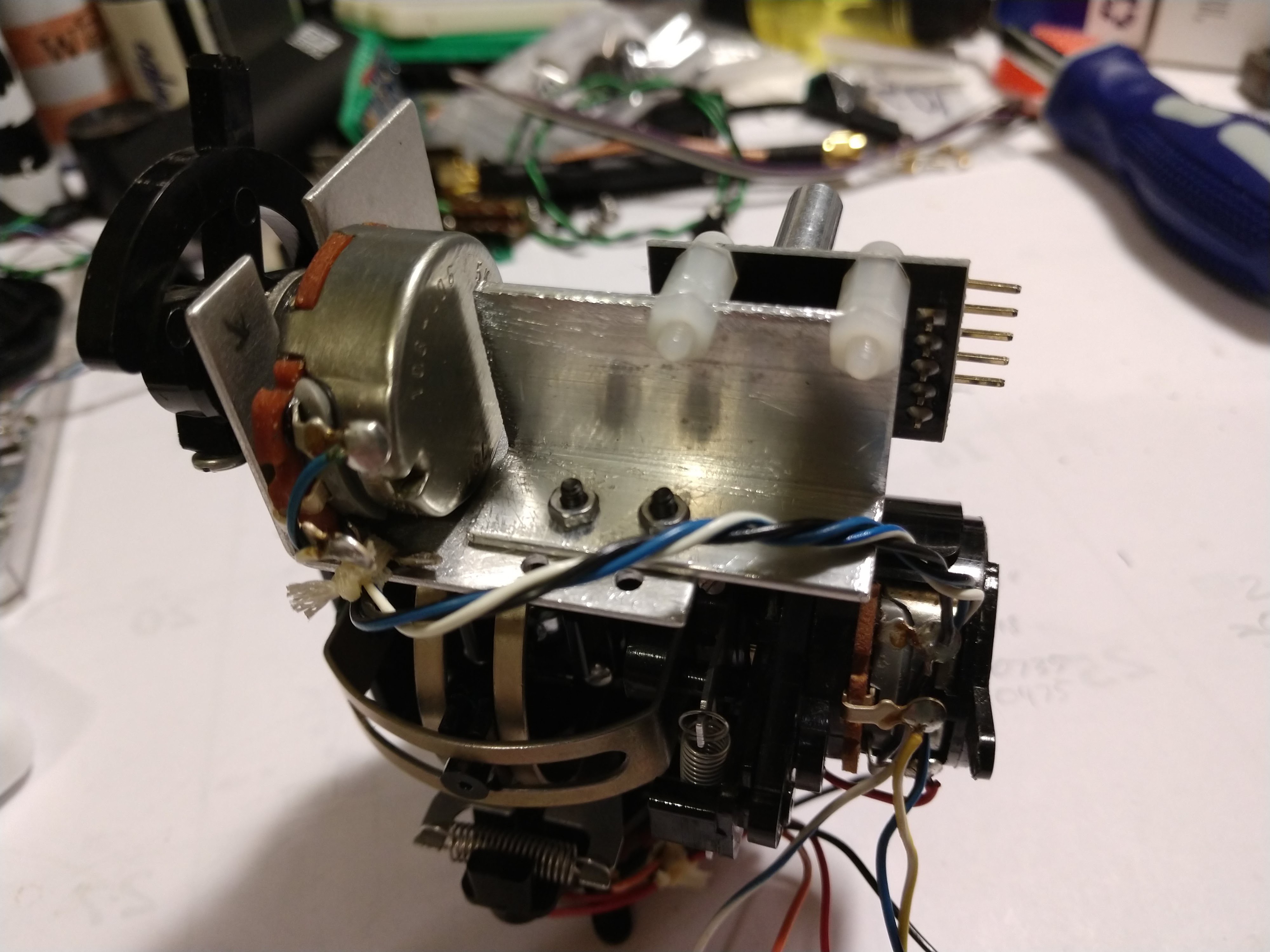
This is also the time to add the rotary encoder. I used some 1" angle aluminum from Lowe's and made a bracket to hold the encoder, then attached my bracket to an existing bracket that holds another pot above the right stick.
![]()
![]()
Hole and encoder locations were calculated by measuring 47 times and still putting the holes in the wrong place.
Hopefully your encoder shaft lines up to where you want it to poke through the transmitter's face. If not, keep on trying until it's where it is supposed to be. Then lay out and drill a hole in the transmitter just big enough for the encoder shaft to fit through. By making it a hair small it allows you to see where the shaft actually is, and then you can embiggen the hole in the direction it needs to go to match. If it doesn't match up by a lot, there is absolutely nothing wrong with needing to re-figure your mounting bracket at this point. We've all been there. Anyone who says differently is selling something.
![]()
![]()
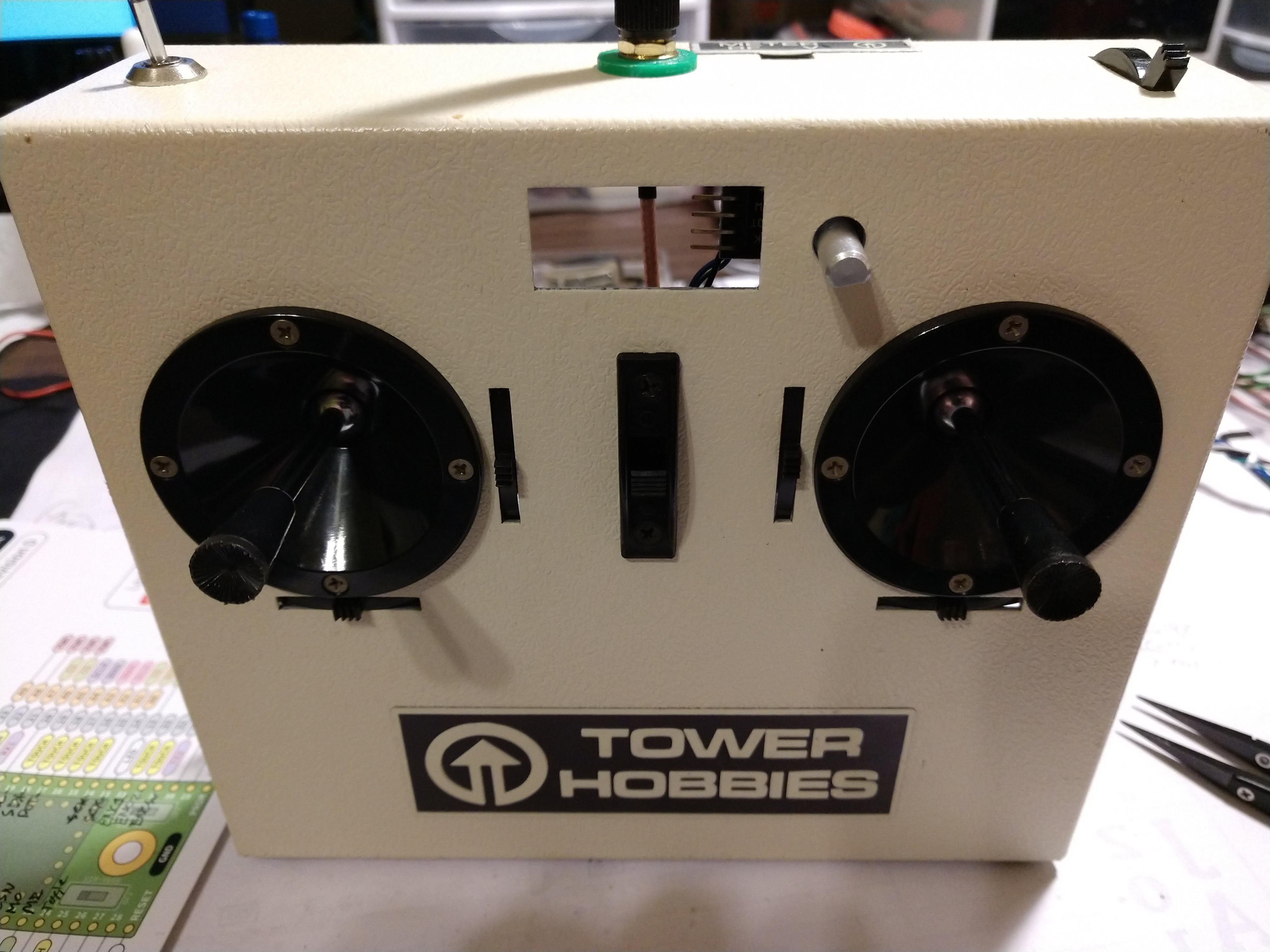
Where the parts actually ended up
-
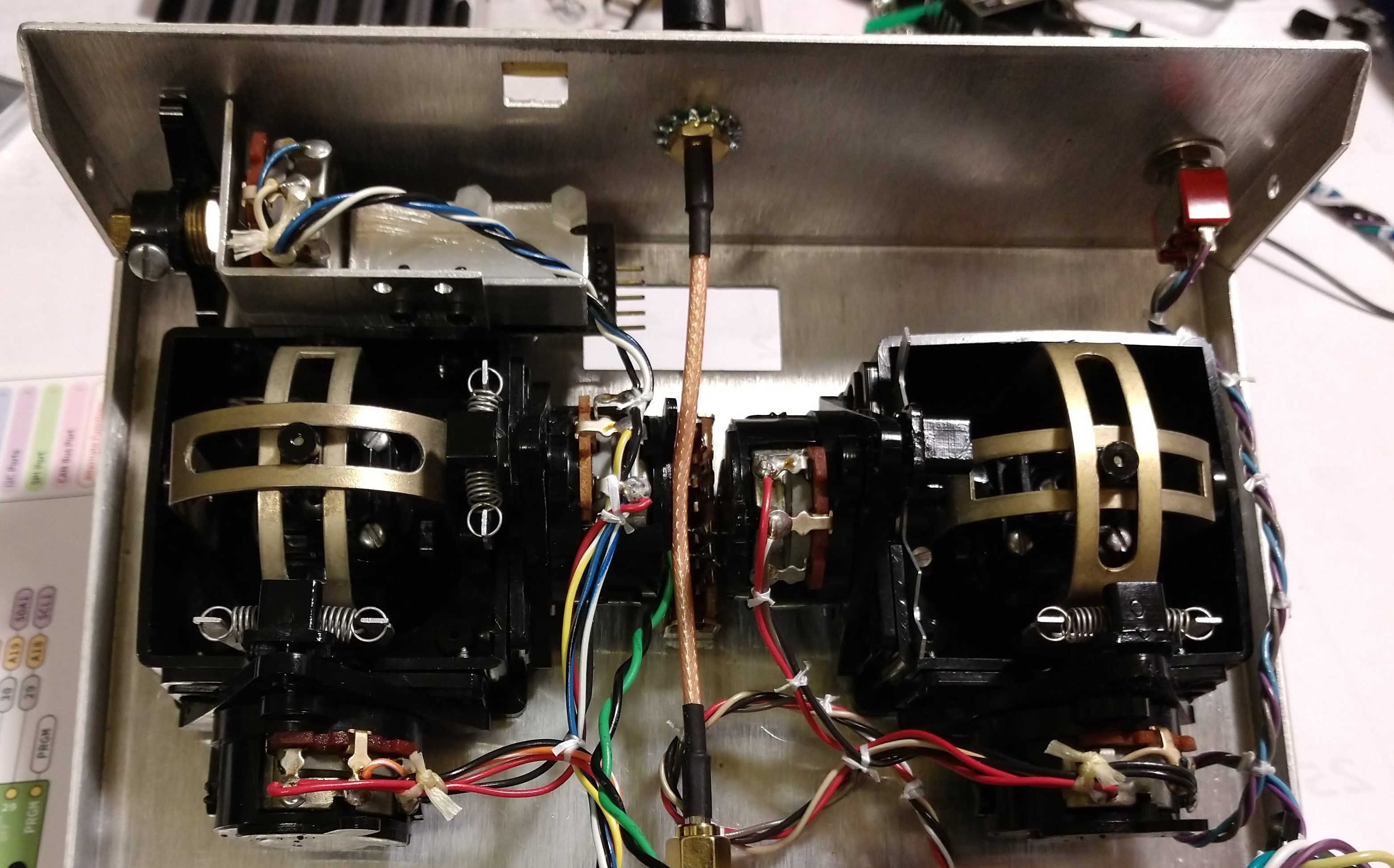
4Add the microcontroller
This step is pretty simple. Decide where you want your microcontroller to live inside the transmitter, then attach it as desired. I went with drilling a couple more holes in the bottom of the transmitter and mounting the Teensy-on-breakout-board to brass standoffs there. This, helpfully, allowed me to connect ground to the whole of the transmitter housing, which I guess is a good thing when it comes to mounting the antenna.
![]()
Please ignore the battery box and radio module for the time being
-
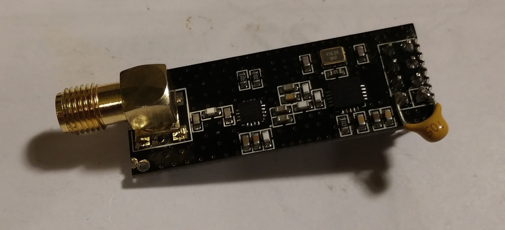
5Add the radio module
I am just using one of those cheapo NRF24L01+PA+LNA radio modules. You may have read something about how poorly these actually work. While this project certainly doesn't need 1 kilometer range capability (you should never, ever use this radio to fly/drive something out of your visual range!) it wouldn't hurt any to try to clean things up a bit. As such, I soldered a 1µF ceramic capacitor across the module's V+ and GND pins and clobbered together a shielding as well.
![]()
Little capacitor across pins 1 and 2
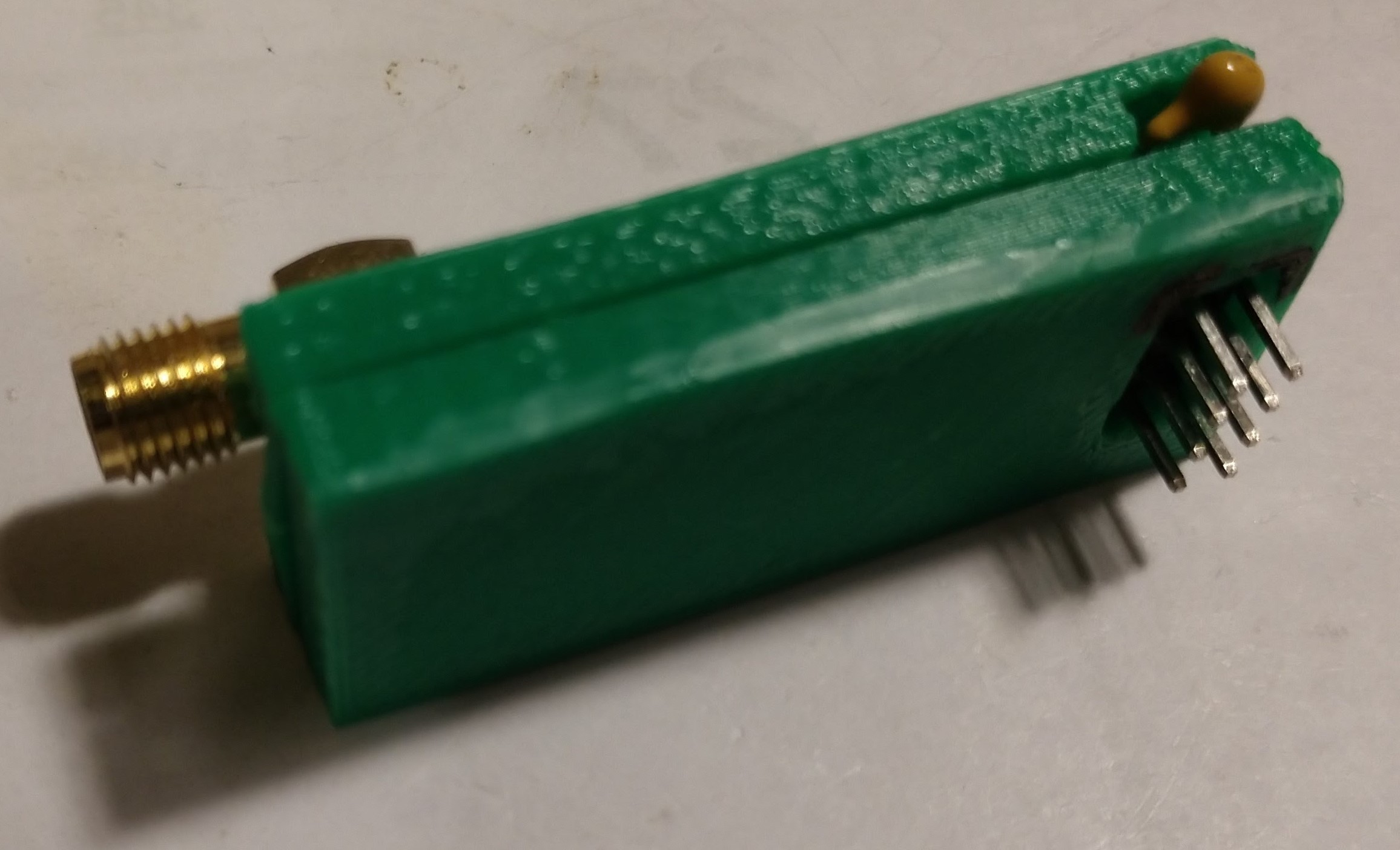
Before trying to wrap it, I found and 3D printed a little housing to hold the module. It did take some filing and finagling to get the module to fit. I think my 3D printer is out of whack... Plus there was that capacitor sticking out the side.
![]()
Soft focus makes the print quality look better
![]()
I've had a sheet of sticky-back copper foil for I don't know how long. If you don't have any, aluminum foil does work they say.
If you are able to use copper sheet or similar, you may find that you have to use several different sized or shaped pieces to cover the whole thing. We want the whole shield to be grounded, so you may need to solder the bits together like this. Remember there is a 3D printed box beneath the shield, so be swift with your soldering! When the whole shield conducts, put another solder connection from the shield to the antenna connector. That will supply the shield with a GND connection.
![]()
Ugly, but it's conductive all over
Because there wasn't enough space in between the gimbals I grabbed an antenna extender. This had the bonus of giving me a panel-mountable connector for the antenna. The existing antenna hole was too big so I whipped up a connector embiggener (or is it a hole ensmallener?) and grabbed a 1/4" toothed lock washer from the Ace Hardware down the street.
![]()
-
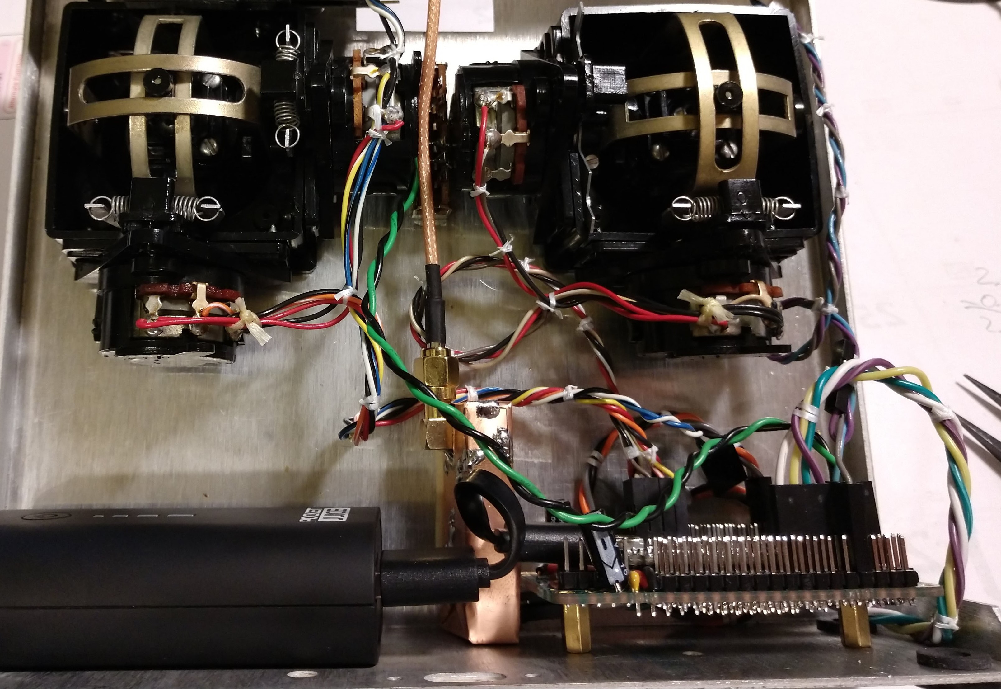
6Give it some juice
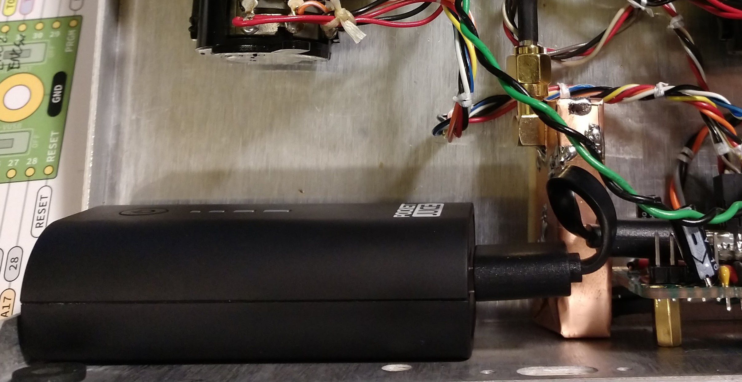
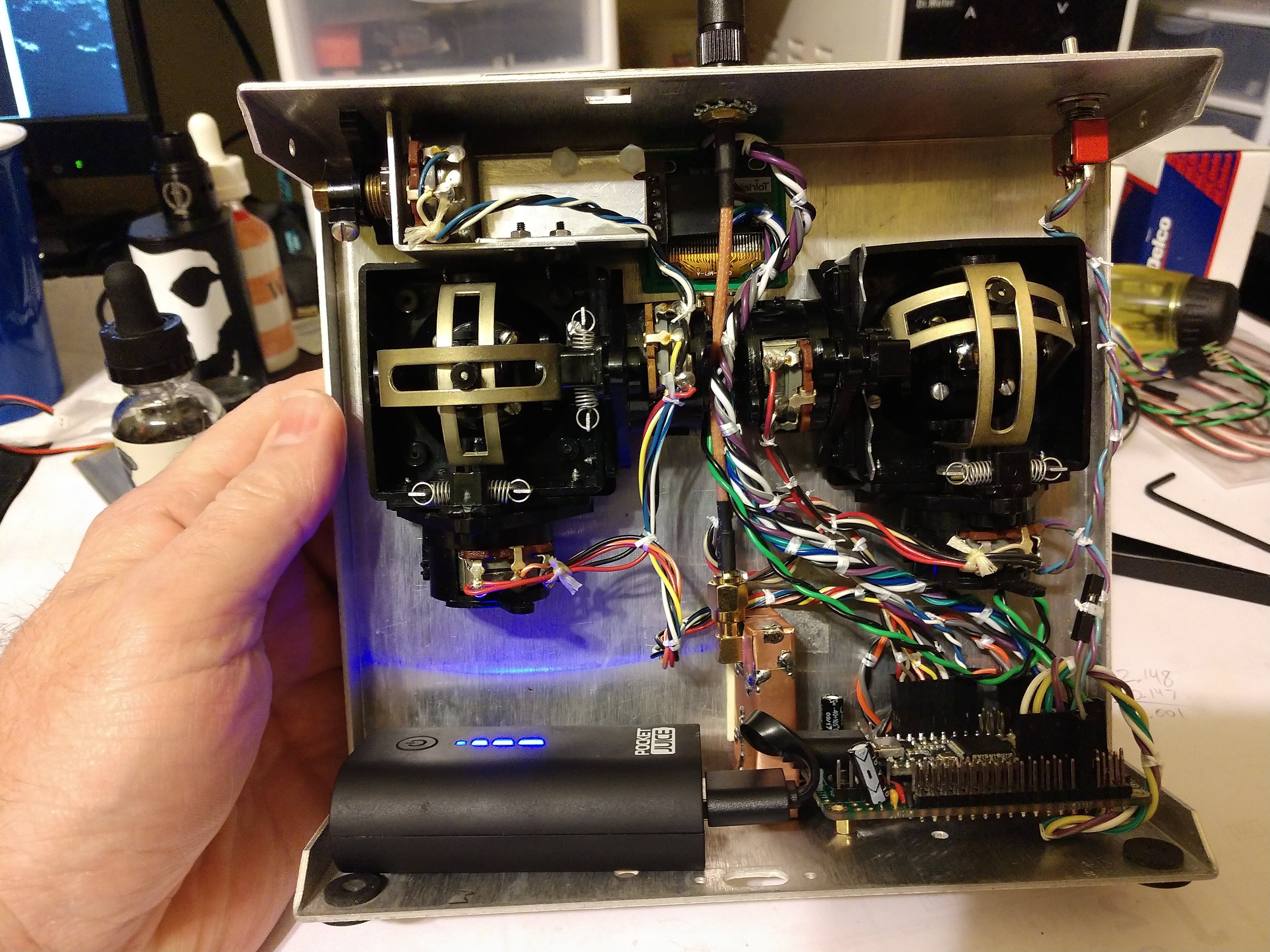
So we need to power this thing somehow. At some point in the last year I picked up one of those portable power bank phone recharger thingies at Best Buy. As I recall it was clearanced for like seven bucks.
![]()
According to its labeling it's 2200mAh and can handle putting out 5VDC at up to 1 amp.
There is a micro-USB port on one side for charging the brick, and a full-size USB A port on the other for powering a Teensy (okay, fine, or for charging a phone). Just a short cable connects it to the Teensy's micro-B connector.
![]()
I'll probably put a length of velcro cable-keeper to hold it in
Now flipping the transmitter's power switch connects VUSB to VIN and fires up the whole shebang. The Teensy's 3.3V regulator seems to be sufficient for powering the NRF24L01+ so far, at least I haven't seen any problems.
That said... Without breaking open the power bank I have no way of knowing the status of the battery. Yes, this one does have that LED "meter" on the front, but that's hidden away inside the transmitter during use. I believe I will likely change over to separate battery and charger parts in the future. Update: See Step 8
-
7Wrap it up (maybe)
That's about it. Now everything should be in the transmitter, and it's time to add some code. As of this writing the remote only handles commanding a Crazyflie 2.0. If you're looking to do the same, grab "rudRemoteCrazyOnly" from the repository, edit it to match your pin connections and min/max findings from step two, and upload it to your microcontroller. Then plug the portable power supply into the Teensy and secure it into the transmitter as you see fit.
![]()
The charging jack for this power brick is a micro-usb port that sits just above the edge of the Tx with the back off, which should make charging simple.
Put the back on the transmitter, fire up your Crazyflie 2.0, then turn on the transmitter. After a few seconds you should see the green connection LED on the Crazyflie start flickering. That means it's talking to the transmitter, and you should be good to fly.
If you're wanting more than just Crazyflie abilities, stay tuned, I'll be working on the software end shortly (now that I've got some documentation done). Update: See Step 9
-
8Upgrade the power
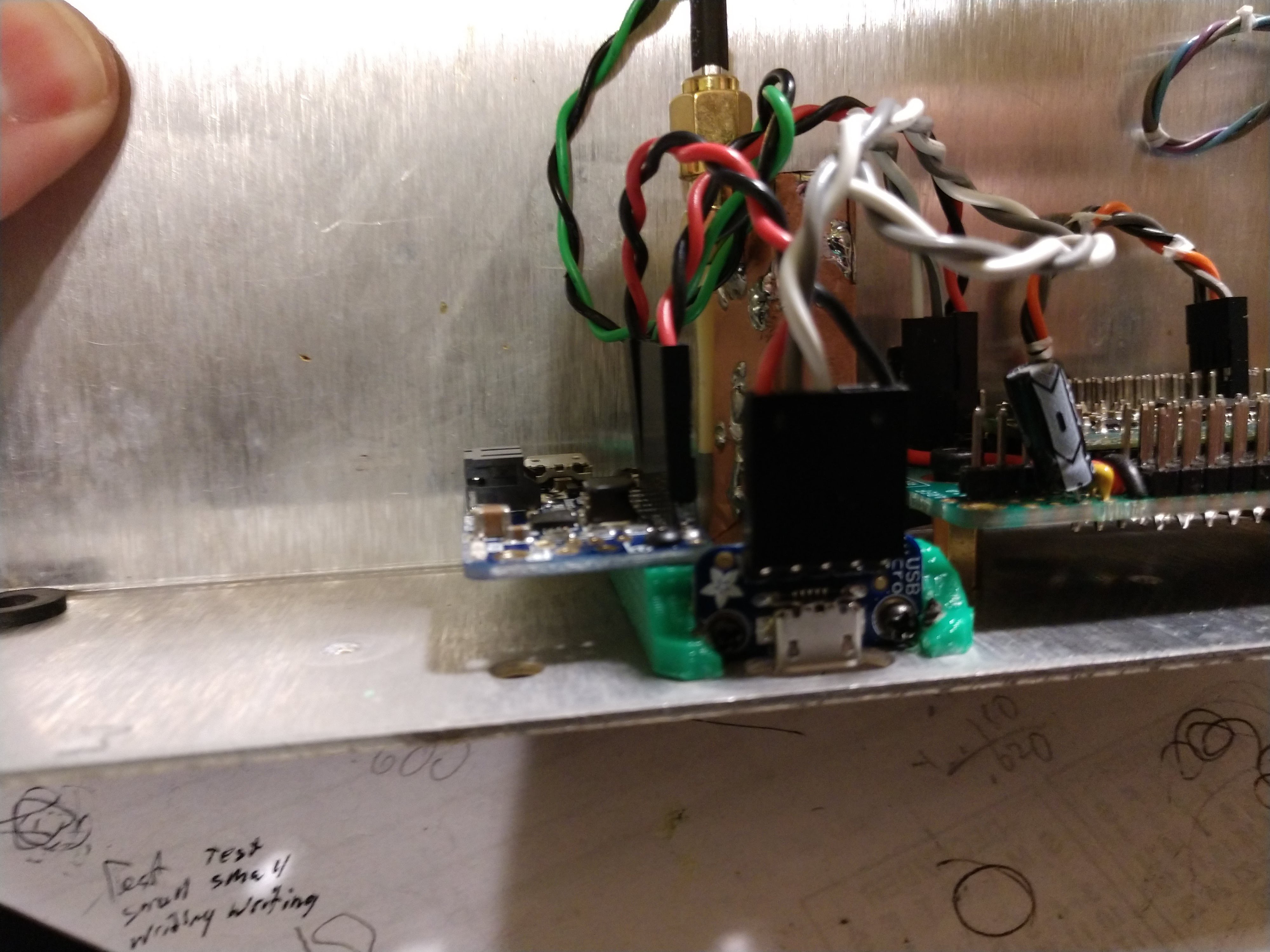
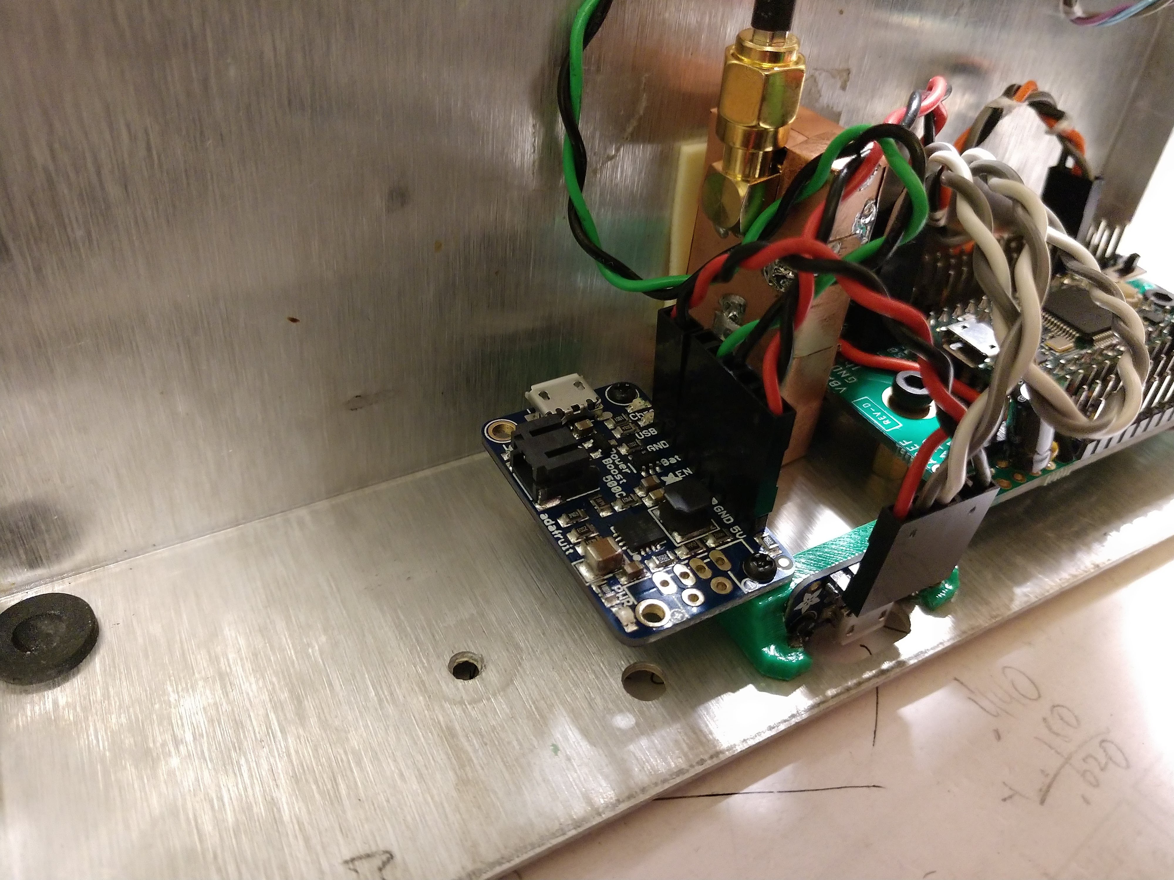
As mentioned at the end of Step 6 I wanted to do something better for powering the remote. To accomplish this I grabbed a PowerBoost 500C, a USB Micro-B breakout board, and a 2000mAh battery from Adafruit.
Whip up a holder-thingie to hold the PCBs to the remote's body, and use a wee bit o' double-sided tape to hold down the battery.
![]()
![]()
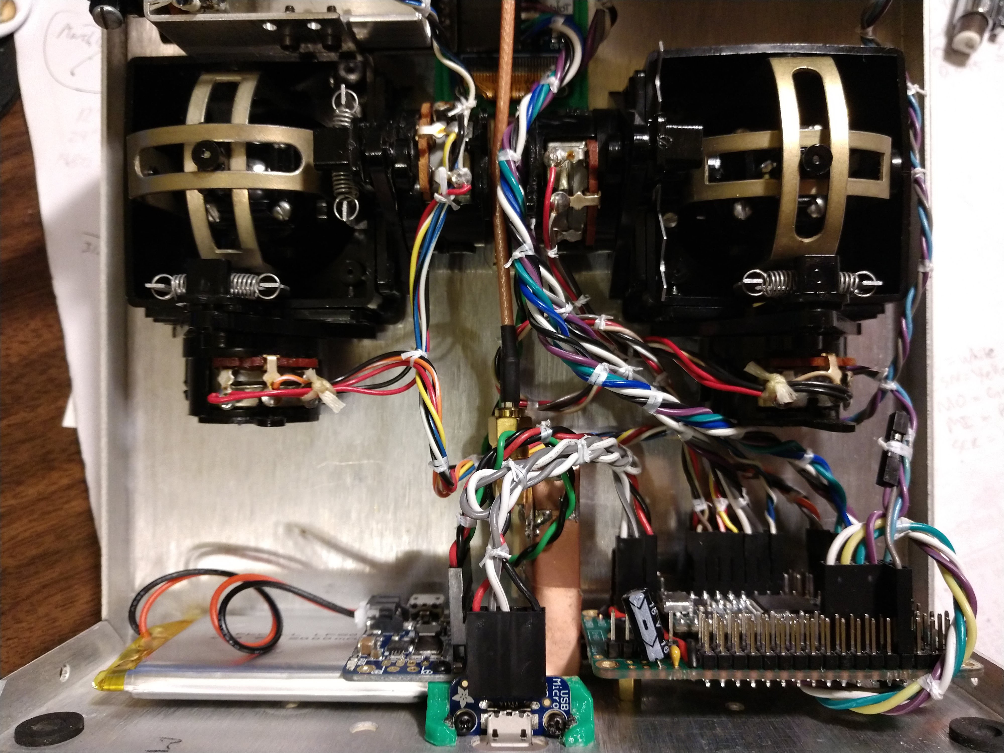
Connect the micro-b breakout's 5V and GND to the USB and GND pins of the PowerBoost 500C. Then connect the power switch to the EN and GND pins of the Powerboost 500C, which are conveniently located next to each other. Lastly, connect the D+/D- pins of the breakout to the same pins of the Teensy (by way of the Teensy 3.2 Breakout, if using that part).
![]()
Looks like this when all mounted up
Connecting the USB's power to the PowerBoost and the D+/D- lines to the Teensy allows for charging, programming, and Serial() communications using the same port. More importantly, it lets the remote be charged without having to open it up.
-
9Let's give it something to talk about, er, to
A transmitter that doesn't have a receiver is like a mule with a spinning wheel. Wait, no it's not. It's like a... whatever. It doesn't do a whole lot unless there's a receiver to talk to. So I've whipped up an example robot that takes input from rudRemote and drives around as you tell it.
For now the code is just the example robot, basically a proof of concept. The plan is to evolve it somewhat into an Arduino library that can simply be included into an existing project.
There isn't a whole lot to it. The receiver code just receives the information from the NRF24 and makes it available to the rest of the code. In other words, rudRemote spits out gimbal/potentiometer/switch/button/whatever data over the NRF24, rudReceiver sucks it up and makes those numbers available for use. For example, channel 1 is just an int16_t that ranges from -511 to 511, with 0 being center. If you want to use that number for pitch control, fine. If you want to use it to tilt a camera or robot head, bend an elbow or knee, wave a flag, whatever, that's fine too. In the Mr. General example it's used for forward/reverse drive speed. What you do with the numbers is up to you.
So, the upshot is, as of today, rudRemote officially can fly a Crazyflie and/or pilot a really slow robot. Just grab the robot code and edit to your heart's content. All you need to do is alter the loop() to do what your project needs.
rudRemote
Customizable NRF24L01+ radio control for multiple vehicles (AKA making a 40 year old radio fly a quadcopter!)
Discussions
Become a Hackaday.io Member
Create an account to leave a comment. Already have an account? Log In.