 repkid
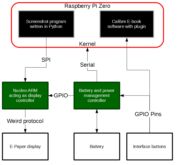
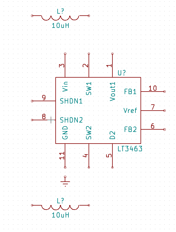
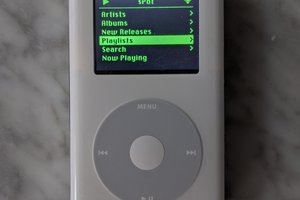
I'll be using the 6 inch ED060SC4 e-paper display (EPD)(electrophoretic display), a.k.a. the kindle replacement screen, because there is a lot of information on it. I'd prefer an 8 inch screen so that is definitely a stretch target. In the first revision I plan to drive the EPD directly with Raspberry Pi's GPIO pins. Once that is working I'll have enough knowledge of the display to make an fpga driver for it that is SPI addressable. With an FPGA driver I plan to implement 1,2,3 and 4 bit colour depth.
The software will probably be written in processing.py due to support for the raspberry pi and the ease of creating a GUI. Secondary choice would be processing in Java mode.
I plan to use a 10000mAh battery so that it won't need to be charged very often.
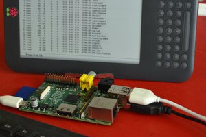
The raspberry pi for this project will be the zero (RPZ) due to low power consumption and suitable form factor. Also, the USB-OTG port will allow me to make the pi read as flash drive which will make transferring files a lot easier.
 Back:
Back:
 Back:
Back:

 j0z0r pwn4tr0n
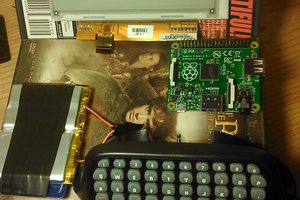
 Guy Dupont
 Pep3175
Well this a long time since the last update but I might as well ask:
How do you breakout the pins on the display's ribbon cable and connect them to the nucleo ARM chip?
Also why have you chosen to take screenshots and send those through SPI instead of sending the text directly to the display controller?
I have been contemplating a project like this and want to figure out some of this kind of thing before i begin ordering parts.