Close
0%
0%

CurrentRanger

Auto-ranging nano-amp current meter

Similar projects worth following
CurrentRanger is a nanoAmp current meter featuring auto-ranging, uni/bi-directional modes, bluetooth data logging options and more.

It is a highly hackable and affordable ultra low-burden-voltage ammeter, appropriate for hobby and professional use where capturing fast current transients and measurement precision are important.

Quick Highlights

Here are some of the features of this instrument which sets it apart:

  • Low noise zero-offset with 3-ranges (1mV output per nA/µA/mA)
  • Low input burden voltage, high precision & bandwidth analog outputs
  • Increased flexibility and usability with several input and output terminal options
  • Auto-ranging capable
  • Use standalone with a small OLED display or with a multimeter/oscilloscope
  • Ultra fast range switching between any ranges (even nA to mA) without any glitching/bouncing of a mechanical switch
  • Low Noise design, helps making nano amp measurements with oscilloscope
  • Low Pass Filter mode – very useful to capture low noise  signals on oscilloscopes
  • Unidirectional mode – most used mode in measuring DC currents ranging from [0, 3.3A]
  • Bidirectional mode – split supply biasing allows AC currents measurement ranging from [-1.65A, 1.65A]
  • LiPo battery powered – long life and extended measurement range
  • Auto-power-off (default: 10 minute inactivity), uses just 0.5uA when OFF
  • Full digital control for power & range switching via touch pads
  • OLED display option to read output with usable precision
  • Datalogging possible via Bluetooth serial module
  • SAMD21 Cortex M0+ powered, change firmware to your needs
  • Optional buzzer for audible feedback

A detailed Current Ranger User Guide is available.

Specs & Architecture

  • Current ranges output:
    • 0-3300 nA/µA/mA (Unidirectional mode)
    • +/- 0-1650 nA/µA/mA (Bidirectional mode)
  • Burden voltage:
    • 17µV/mA
    • 10µV/µA
    • 10µV/nA
  • Output offset voltage¹: typically <10µV, max 50µV
  • Maximum input voltage differential (see Safety): 33mV
  • Accuracy:
    • +/-0.05% (µA, nA ranges)
    • +/-0.1% (mA range)
  • Highest resolution (nA range):
    • 100pA (3.5digit meter)
    • 10pA (4.5 digit meter)
    • 1pA (5.5 digit meter)
  • Cascaded MAX4239 amplifiers with 100x output gain
    • Bandwidth: >300KHz (-3dB)

Note¹: it may take a few minutes from power ON for the offset to reach its lowest value (ie. warm-up).

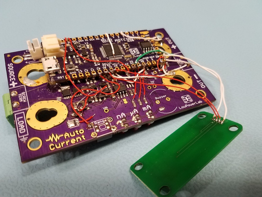
Principle of operation

At the heart of the CurrentRanger are two MAX4239 ultra low offset auto-zero 6Mhz unity gain bandwidth amplifiers. They are configured in a non-inverting 10x gain each using high precision resistors, totaling 100x output gain.

There are 3 high precision shunts (10mΩ, 10Ω, 10kΩ) at the input of these amplifiers yield the 3 current sensing ranges possible.

While the amplifiers, topology and shunt configuration of the CurrentRanger are similar to the µCurrent by EEVBlogCurrentRanger is a product with significantly different features and goals.

The CurrentRanger employs switching dynamics to selectively enable/disable the shunts to allow for manual or auto-ranging.

The analog sensing is done by the SAMD21G18 ARM Cortex M0+ 48Mhz processor which samples the output through its 12bit ADC. The SAMD21 also controls all aspects of switching, digital interfacing, and power control of the unit.
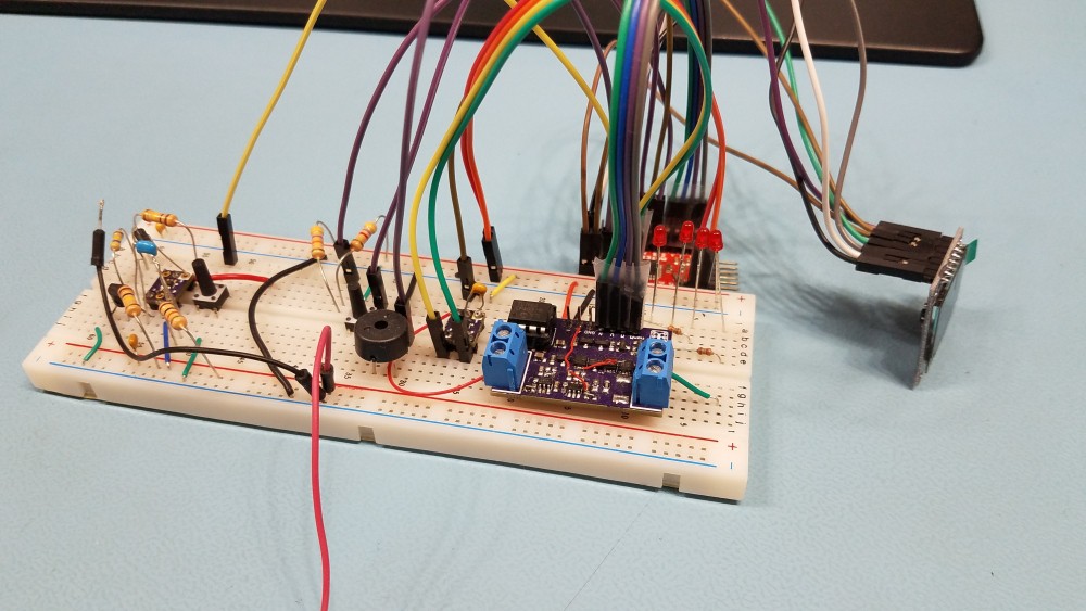
Development efforts

A lot of development and experimentation were invested to bring this product to reality. And it could still be improved, made lower noise, enhanced with more features, etc. This is where you – the user – have an opportunity to contribute with suggestions, analog and EE expertise and coding optimizations.

  • 1 × ATSAMD21G18A ARM Cortex M0+ 48Mhz
  • 2 × MAX4239 Ultra low offset 6Mhz opamps
  • 9 × High Precision shunts and amplifier gain resistors

  • 1
    Step 1

    Assembly & Terminal options

    Choose from several types of terminals:

    • 5.08mm spaced thumb/screw terminals – most convenient and quick to use at input, can also be mounted at output
    • “GOLD” banana jack/screw terminals – mount on input/output
    • low profile banana jack terminals – mount on input/output
    • pin headers may also be soldered at various points for easy snap-on DMM probing
    • dedicated pin-hole output for low inductance oscilloscope probing
    • many other potential options

    The “gold” terminals mount in the smaller aperture of the terminals. A set of 3D-printed half-moon washers are provided to prevent these terminals from sliding in the mounting hole.

    The lower profile banana jacks will mount in the larger apertures of the output terminals.

    The above photo also illustrates the suggested mounting configuration for the terminals, but you may mount in any other way you find useful.

    Some of the gold terminals may not flat mount on the PCB, and so it’s recommended to use the included washers to help keep them straight and make good contact.

    Here is another mounting example by a user who chose not to use the 3D printed inserts, the extensions of the rectangular washers could be bent like the photo shows or cut off entirely:

    Case modifications

    The PCB mounting pillars in the provided ABS case are slightly recessed. If you use the green thumb terminal (which extends beyond the PCB and the case wall) you must make a 12mm wide notch to seat the terminal properly and avoid the risk to damage it or its solder joints when you screw the PCB to the case. Draw the outline of this notch with a marker and use a utility knife or equivalent tool to carefully carve this notch out.

    It may also be convenient to make a rectangular cutout in the provided ABS enclosure for easy USB port access. Draw the outline of this cutout with a marker, then you may use a thin drill to carve out the bulk of the hole, then carefully remove the edges with a utility knife.

    Dimensions and offsets are illustrated below, make sure to be careful and safe when using sharp tools:

    If you solder the optional buzzer, you will also need to remove the retainers shown below, opposite the USB connector, where the buzzer will be next to the case wall, to make room for it:

View all instructions

Enjoy this project?

Share

Discussions

hilamforex90 wrote 05/15/2023 at 13:06 point

There has been a great deal of value to me in my involvement with the project. Would like to share it with the family planning gold coast team so they can also read it and implement something new.

  Are you sure? yes | no

Blecky wrote 11/13/2019 at 13:25 point

Just a quick question about hookup. Is there any risk of damage to the device if it is hooked up the wrong way around by accident? I.e. connect the load to the OUT jacks?

  Are you sure? yes | no

Felix Rusu wrote 11/13/2019 at 14:33 point

I haven't tried that :-)
But I would not recommend it. I am sure it can be damaged that way.

  Are you sure? yes | no

Blecky wrote 11/13/2019 at 15:24 point

Noted :)

  Are you sure? yes | no

Blecky wrote 10/17/2019 at 07:52 point

Just received my CurrentRanger. Great job on the board and firmware. Everything feels pretty schmick.

The only downside (but I'll change this in the firmware myself) is that you can't play Mary had a Little Lamb straight away since the buzzer doesn't sound on a button when it's active and you press it again.

  Are you sure? yes | no

Felix Rusu wrote 10/17/2019 at 13:25 point

Thanks for the feedback, Hey maybe I should add a little MENU where you can turn "always buzz" ON-OFF to get your 3 key piano (-:

  Are you sure? yes | no

alexwhittemore wrote 03/18/2019 at 19:20 point

I'm also interested as Dan is in having some kind of GPIO output to indicate range. It looks like, from your reply, you broke out the "SPI+D3" header for nothing in particular, but just because the IO was there and a user might come up with something for it?

I'm imagining I'll implement a version of the firmware that outputs a range indication on each of those pins. For instance, pin 1 high in nA range, pin 2 high in uA range, and pin 3 high in mA range. That way, on a mixed signal scope (I'm thinking Digilent Analog Discovery), I can set up a Math trace that is something like (A1*D1*1e-9)+(A1*D2*1e-6)+(A1*D3*1e-3)=current (Amps). In so doing, I can then use whatever waveform analysis to do the integration/cursors/etc.

Are you aware of anyone having done this work already, or have you done it yourself? For measuring things like microcontrollers swinging from sleep to LED lightshow, it seems like it'd be the most useful option on the market. There are a few devices ranging from attainable (Atmel atpowerdebugger, SiLabs STK "Advanced Energy Monitor"/Energy Profiler) to unobtainable (I think J-Link makes a J-Trace with energy profiling that costs $$$), but those devices still don't have the dynamic range of the CurrentRanger - the atpowerdebugger has two separate channels, one for 100mA and one for 1A, so you MIGHT be able to use that depending on your target hardware but I'm not sure if you can, say, put the high-drain stuff on one channel and the MCU on the other, simultaneously. But I know the AEM on the SiLabs EFM32 STK boards tops out at 100mA. 

It'd be killer to have a solution that does (nA-A)-to-trace for easy post analysis. 

  Are you sure? yes | no

alexwhittemore wrote 03/18/2019 at 19:31 point

Sorry, the SiLabs AEM actually does .1uA to 50mA, so a bit more limiting. Great dynamic range, but not enough to precisely profile an entire system. 

  Are you sure? yes | no

Felix Rusu wrote 03/18/2019 at 19:44 point

Alex,

That GPIO header (it's actually the SPI pins) is left there intentionally to offer ways of experimentation and augmentation to folks like you who don't fear to try fiddling with coding and extending firmware functionality. I'm not aware of anyone doing anything yet with the GPIO. But always a good idea to check in the to see what current users are up to, or any neat customizations.

https://lowpowerlab.com/forum/currentranger/

  Are you sure? yes | no

alexwhittemore wrote 03/18/2019 at 20:38 point

Ahh, a forum link is JUST what I was hoping for, I suppose. Thanks!

  Are you sure? yes | no

Felix Rusu wrote 12/05/2018 at 21:31 point

Interesting point, I haven't taken that into account.

Is this a situation where somehow the potential of the board vs the potential of external load are very different, and some inrush current causes the board MCU to see a brown-out condition?

  Are you sure? yes | no

Dan Julio wrote 11/30/2018 at 22:42 point

Very neat.  This looks like a useful device, Felix.  Instruments like this are definitely useful when designing ultra-low power devices.  I took a look at your schematic and a brief look at the code (but not in depth) and have a couple of questions.

1. How fast are you sampling the ADC when autoranging?  Is it just as fast as the main loop executes (and then 1024 averaged samples at a time?)?

2. In your own testing would it ever have been useful to also output the auto-range to the scope (e.g. did you do testing where the power levels changed enough - say a micro sleeping to waking and then keying on a RF output stage - that during a trace capture the ranges changed)?

Also have you ever experimented with connecting a power supply sense to the output of the current monitor as a way to avoid voltage droops (and perhaps more accurately capture power consumption by keeping a steady input voltage)?

  Are you sure? yes | no

Felix Rusu wrote 12/03/2018 at 14:10 point

Thank you, the "official" firmware ADC is a middle of the road approach - not the fastest possible. It gives a reasonably accurate reading for a 12bit, and it allows reasonably fast switching.

You will see the switching on the scope by very short spikes. If you need digital signalling that's possible by the extra broken out GPIO headers (SPI+D3) which could also be used with SPI devices for whatever purpose.

I guess I don't really understand your last question - but I don't think I tried that.

  Are you sure? yes | no

Dan Julio wrote 12/05/2018 at 21:22 point

Thank you for the information.  The third question was a way to deal with the voltage drop that occurs across the sense resistor(s).  It probably isn't too big of an issue for a lot of situations but I have seen micro-controllers execute a brown-out reset while I am measuring their input current using a shunt resistor and they suddenly require a lot of current.  One solution, which I haven't tried, would be to see if connecting a lab power supply remote sense positive input on the output side of the shunt resistor would deal with that.  Not really directly related to your project but I wondered if you'd ever experimented with that since you have done a lot of current monitoring.

  Are you sure? yes | no

Similar Projects

Does this project spark your interest?

Become a member to follow this project and never miss any updates