 mihai.cuciuc
This is very much a work in progress and most of the requirements are not satisfied yet. But thanks to excellent documentation done by NuclearPhoenix on the All-In-One Gamma-Ray Spectrometer and the Cosmic Pi project I have a proof of concept working.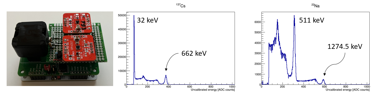
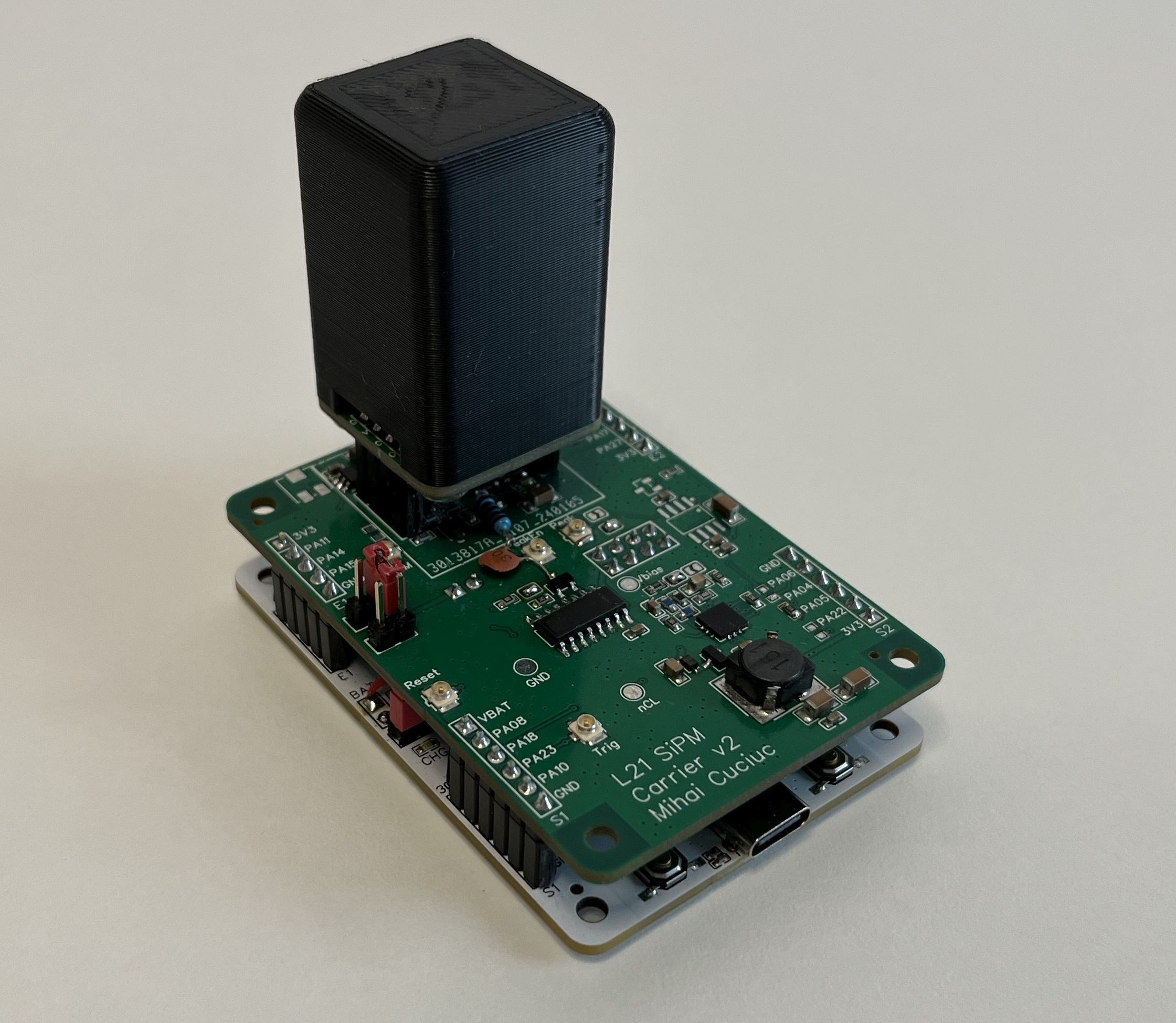
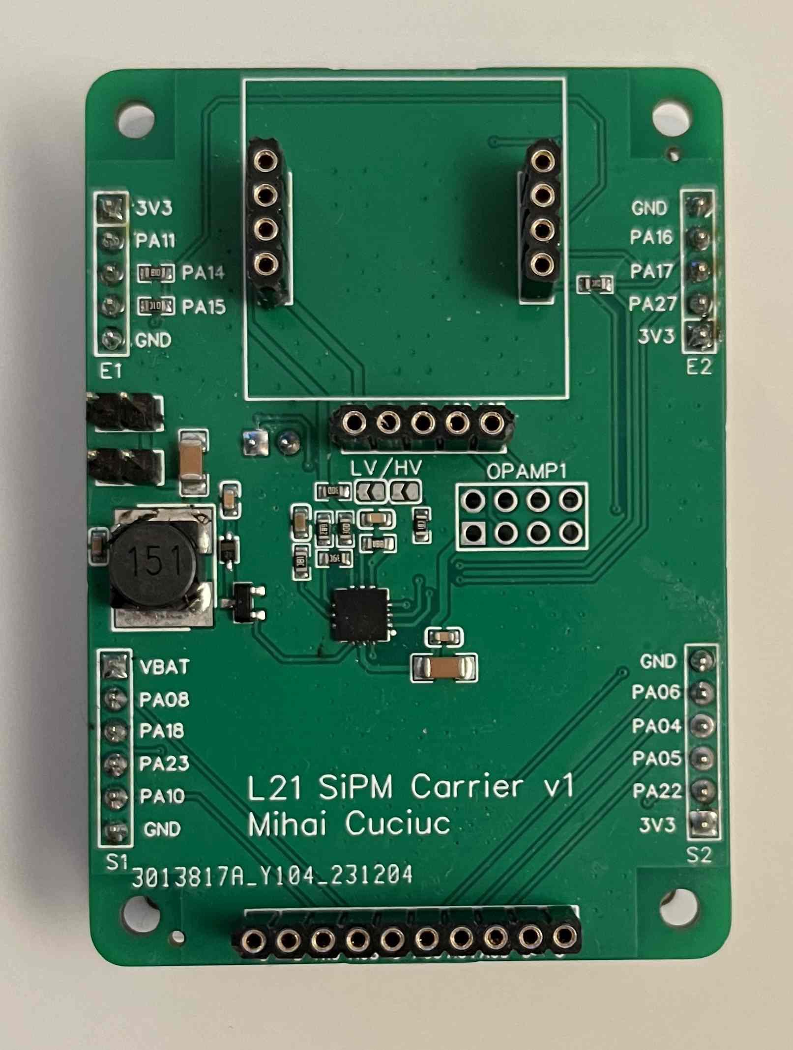
Current version of the hardware includes:
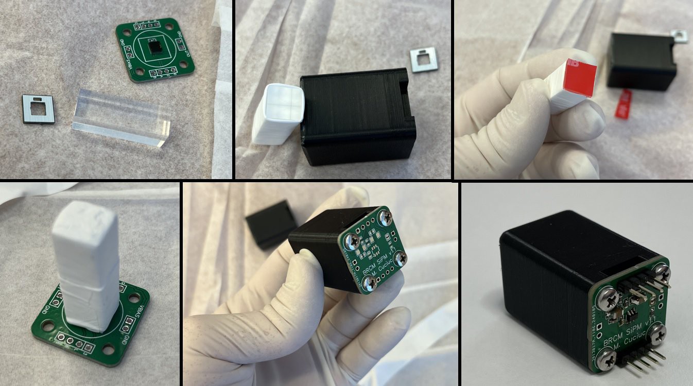
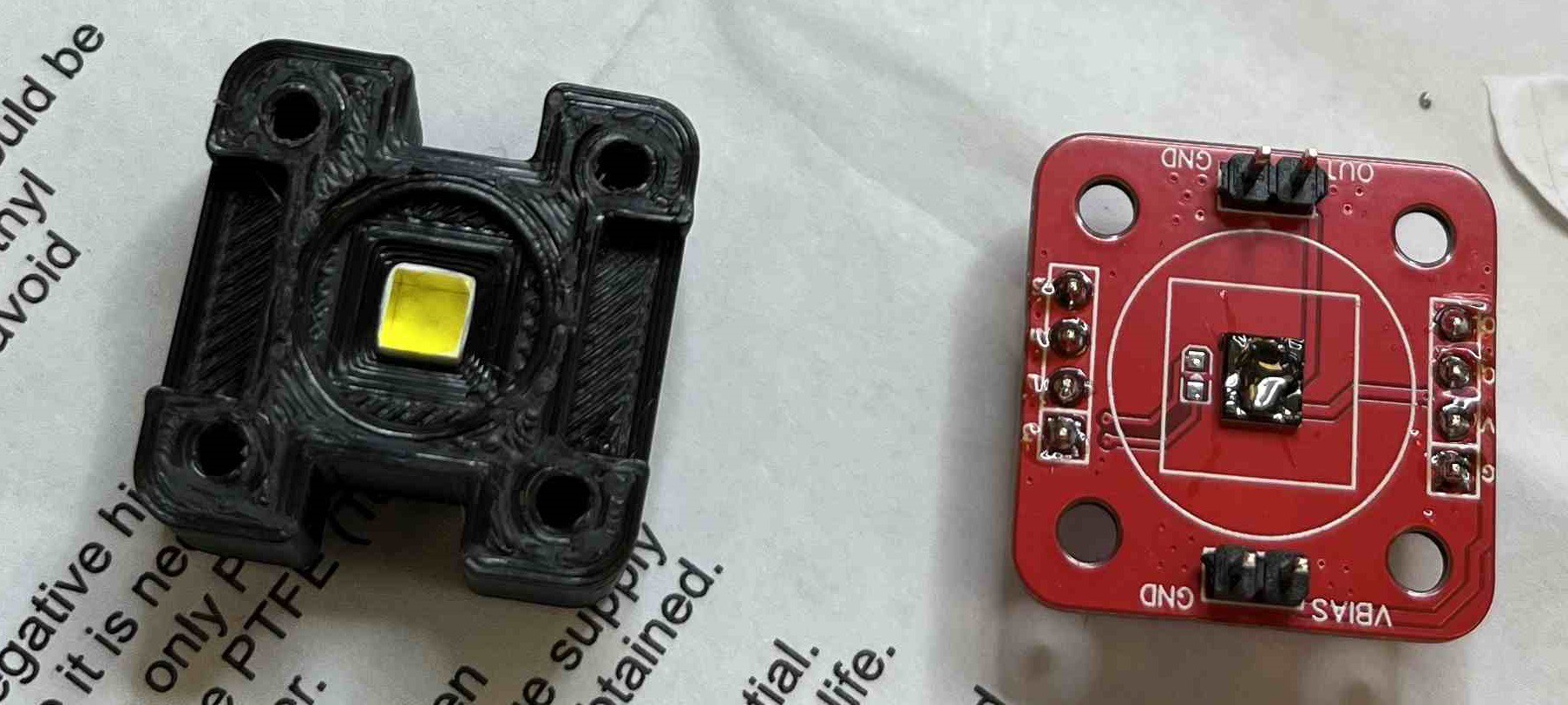
- 4mm x 4mm x 10mm GAGG(Ce) scintillator crystal with light reflector and 3D printed “dark” box
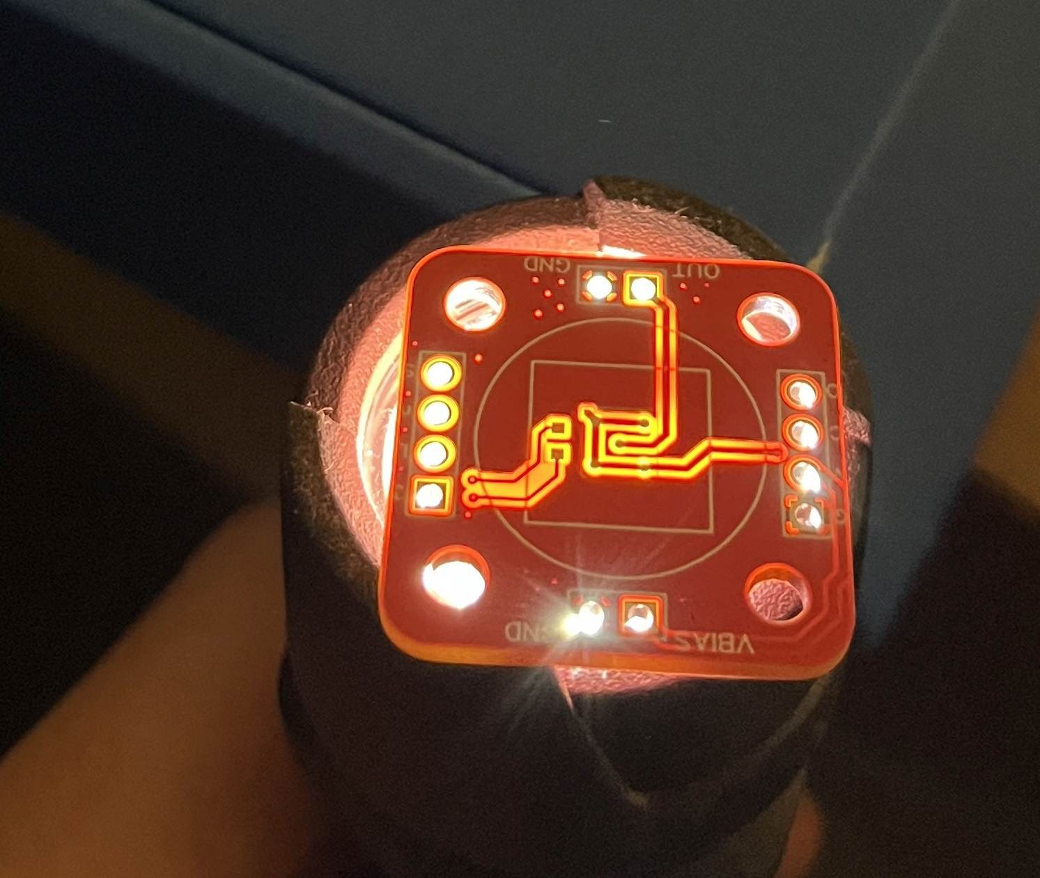
- 4mm x 4mm Broadcom AFBR-S4N44P014M Silicon photomultiplier (SiPM) with optical grease coupling to scintillator
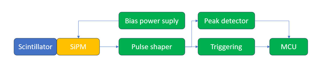
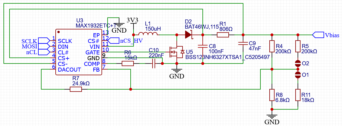
- MAX1932 SiPM bias supply
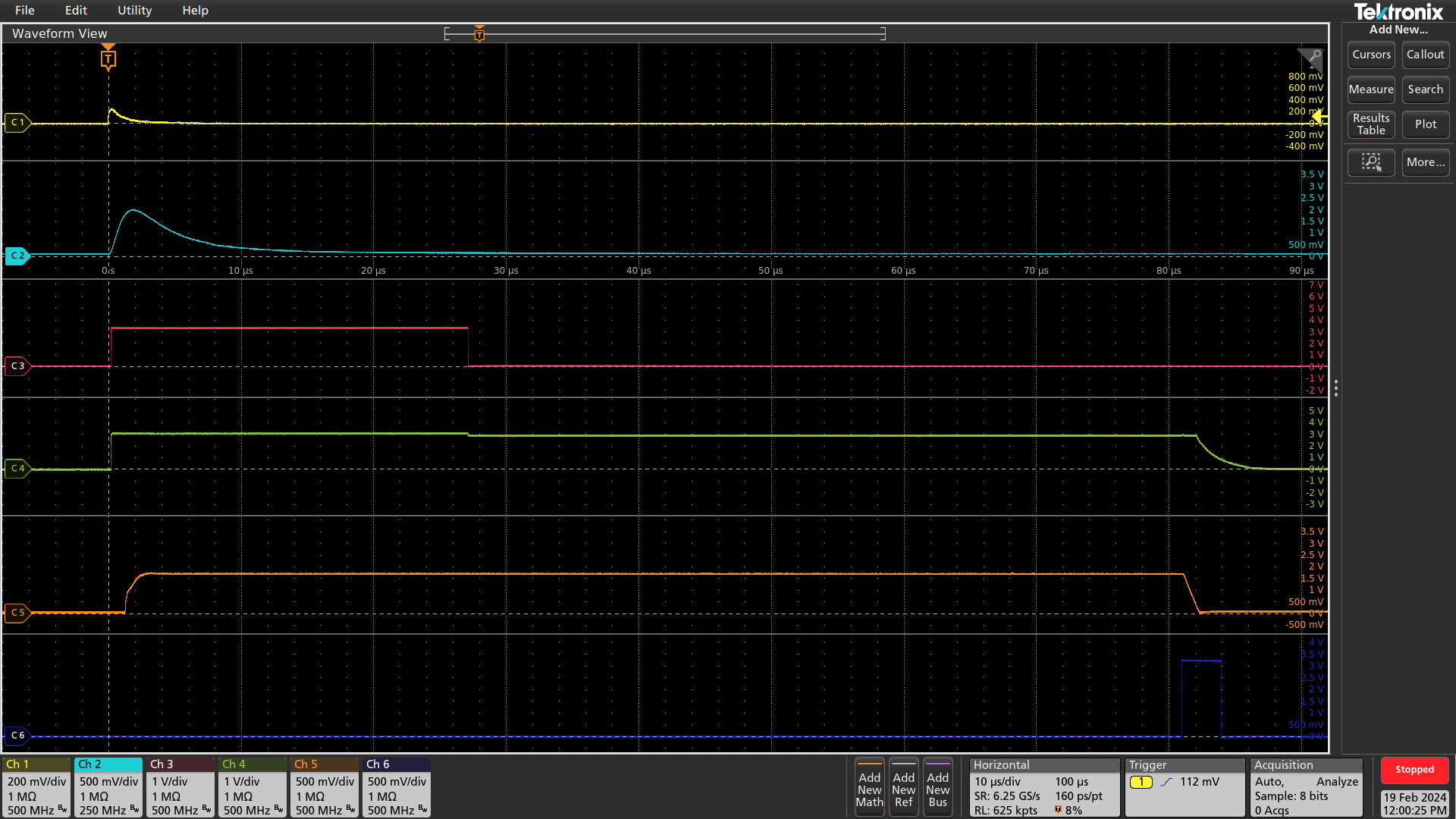
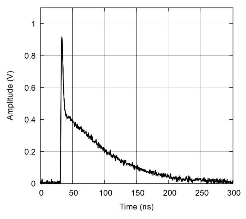
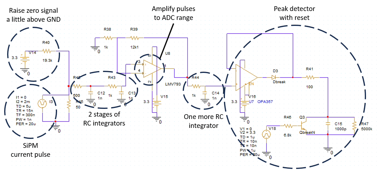
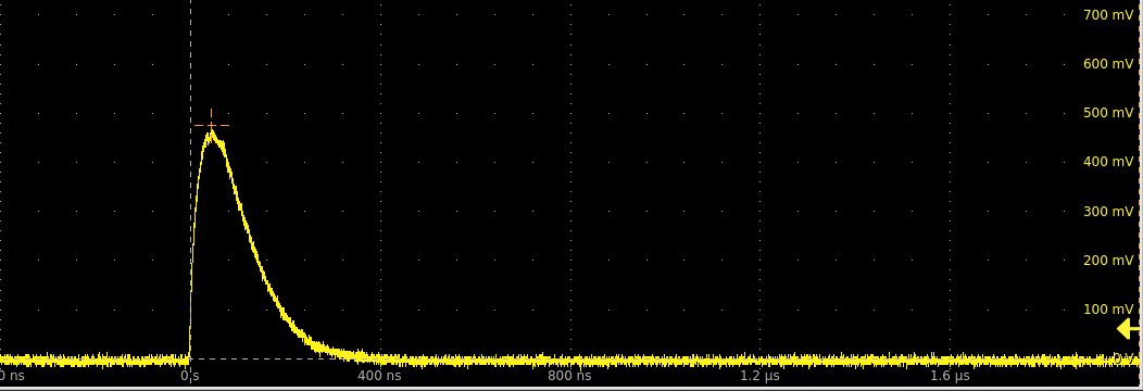
- Shaper to decrease bandwidth of SiPM pulses
- Peak detector circuit
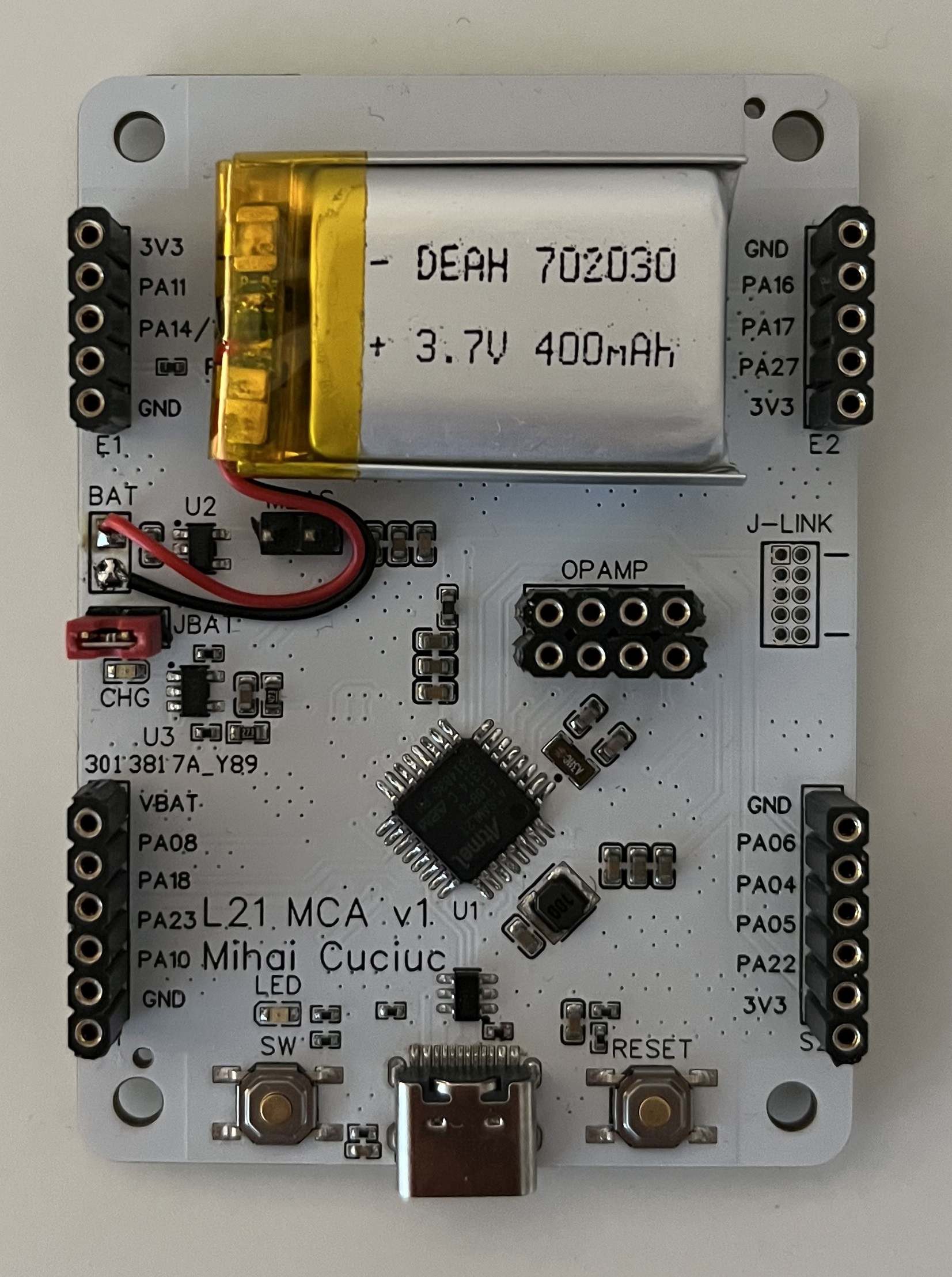
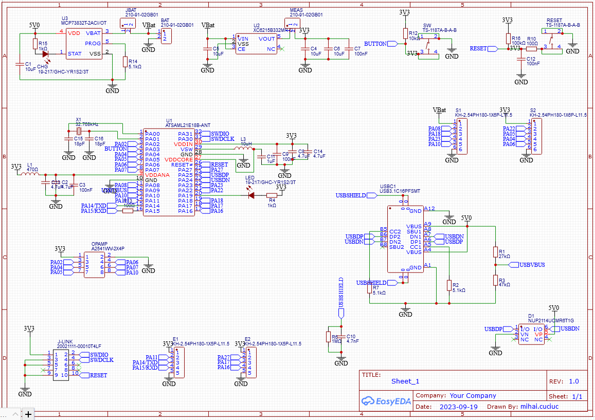
- ATSAML21E18B MCU that performs triggering, pulse height measurement, and peak detector reset
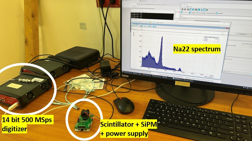
Energy resolution is 14.3% @ 662 keV and 12.4% @ 1274.5 keV.
Architecture


 Yann Guidon / YGDES
 Mitsuru Yamada
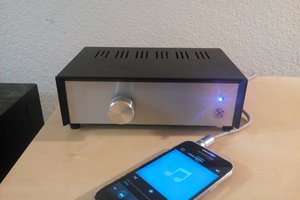
 Szoftveres
Super interesting! How small do you think you could ultimately make the sensor and accompanying electronics?