Yann Guidon / YGDES
-
DepthLists
12/24/2019 at 22:16 • 7 commentsv2.6 is looking good !
I already have the gatelist which is, as the name implies, the list of gates, and their connections are working well. It is now supplemented by the "depthlist", a 2D array of gate references. It simplifies the design of algorithms that scan forward or backward in the circuit.
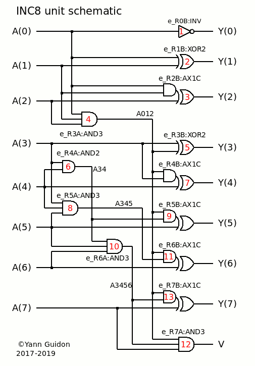
Here is the new display for the INC8 unit :
  ************ DEPTHLIST ************

 - Input #0 : fanout=4
      1 : Gate #1(0) - inc8):dut@inc8(tiles):e_r0b@inv(trace):lut2
      2 : Gate #2(0) - inc8):dut@inc8(tiles):e_r1b@xor2(trace):lut4
      3 : Gate #3(0) - inc8):dut@inc8(tiles):e_r2b@ax1c(trace):lut8
      4 : Gate #4(0) - inc8):dut@inc8(tiles):e_r3a@and3(trace):lut8

 - Input #1 : fanout=3
      1 : Gate #2(1) - inc8):dut@inc8(tiles):e_r1b@xor2(trace):lut4
      2 : Gate #3(1) - inc8):dut@inc8(tiles):e_r2b@ax1c(trace):lut8
      3 : Gate #4(1) - inc8):dut@inc8(tiles):e_r3a@and3(trace):lut8

 - Input #2 : fanout=2
      1 : Gate #3(2) - inc8):dut@inc8(tiles):e_r2b@ax1c(trace):lut8
      2 : Gate #4(2) - inc8):dut@inc8(tiles):e_r3a@and3(trace):lut8

 - Input #3 : fanout=4
      1 : Gate #5(0) - inc8):dut@inc8(tiles):e_r3b@xor2(trace):lut4
      2 : Gate #6(0) - inc8):dut@inc8(tiles):e_r4a@and2(trace):lut4
      3 : Gate #7(1) - inc8):dut@inc8(tiles):e_r4b@ax1c(trace):lut8
      4 : Gate #8(0) - inc8):dut@inc8(tiles):e_r5a@and3(trace):lut8

 - Input #4 : fanout=3
      1 : Gate #6(1) - inc8):dut@inc8(tiles):e_r4a@and2(trace):lut4
      2 : Gate #7(2) - inc8):dut@inc8(tiles):e_r4b@ax1c(trace):lut8
      3 : Gate #8(1) - inc8):dut@inc8(tiles):e_r5a@and3(trace):lut8

 - Input #5 : fanout=3
      1 : Gate #9(2) - inc8):dut@inc8(tiles):e_r5b@ax1c(trace):lut8
      2 : Gate #10(1) - inc8):dut@inc8(tiles):e_r6a@and3(trace):lut8
      3 : Gate #8(2) - inc8):dut@inc8(tiles):e_r5a@and3(trace):lut8

 - Input #6 : fanout=2
      1 : Gate #11(2) - inc8):dut@inc8(tiles):e_r6b@ax1c(trace):lut8
      2 : Gate #10(2) - inc8):dut@inc8(tiles):e_r6a@and3(trace):lut8

 - Input #7 : fanout=2
      1 : Gate #12(2) - inc8):dut@inc8(tiles):e_r7a@and3(trace):lut8
      2 : Gate #13(2) - inc8):dut@inc8(tiles):e_r7b@ax1c(trace):lut8

 Depth 1 : 6 gates.
 - Gate #1 : fanout=1  Depth min=1  max=1  LUT="10" - inc8):dut@inc8(tiles):e_r0b@inv(trace):lut2
      1 : Output #0
 - Gate #2 : fanout=1  Depth min=1  max=1  LUT="0110" - inc8):dut@inc8(tiles):e_r1b@xor2(trace):lut4
      1 : Output #1
 - Gate #3 : fanout=1  Depth min=1  max=1  LUT="01010110" - inc8):dut@inc8(tiles):e_r2b@ax1c(trace):lut8
      1 : Output #2
 - Gate #4 : fanout=6  Depth min=1  max=1  LUT="00000001" - inc8):dut@inc8(tiles):e_r3a@and3(trace):lut8
      1 : Gate #5(1) - inc8):dut@inc8(tiles):e_r3b@xor2(trace):lut4
      2 : Gate #7(0) - inc8):dut@inc8(tiles):e_r4b@ax1c(trace):lut8
      3 : Gate #9(0) - inc8):dut@inc8(tiles):e_r5b@ax1c(trace):lut8
      4 : Gate #11(0) - inc8):dut@inc8(tiles):e_r6b@ax1c(trace):lut8
      5 : Gate #12(0) - inc8):dut@inc8(tiles):e_r7a@and3(trace):lut8
      6 : Gate #13(0) - inc8):dut@inc8(tiles):e_r7b@ax1c(trace):lut8
 - Gate #6 : fanout=2  Depth min=1  max=1  LUT="0001" - inc8):dut@inc8(tiles):e_r4a@and2(trace):lut4
      1 : Gate #10(0) - inc8):dut@inc8(tiles):e_r6a@and3(trace):lut8
      2 : Gate #9(1) - inc8):dut@inc8(tiles):e_r5b@ax1c(trace):lut8
 - Gate #8 : fanout=1  Depth min=1  max=1  LUT="00000001" - inc8):dut@inc8(tiles):e_r5a@and3(trace):lut8
      1 : Gate #11(1) - inc8):dut@inc8(tiles):e_r6b@ax1c(trace):lut8

 Depth 2 : 5 gates.
 - Gate #5 : fanout=1  Depth min=1  max=2  LUT="0110" - inc8):dut@inc8(tiles):e_r3b@xor2(trace):lut4
      1 : Output #3
 - Gate #7 : fanout=1  Depth min=1  max=2  LUT="01010110" - inc8):dut@inc8(tiles):e_r4b@ax1c(trace):lut8
      1 : Output #4
 - Gate #10 : fanout=2  Depth min=1  max=2  LUT="00000001" - inc8):dut@inc8(tiles):e_r6a@and3(trace):lut8
      1 : Gate #12(1) - inc8):dut@inc8(tiles):e_r7a@and3(trace):lut8
      2 : Gate #13(1) - inc8):dut@inc8(tiles):e_r7b@ax1c(trace):lut8
 - Gate #9 : fanout=1  Depth min=1  max=2  LUT="01010110" - inc8):dut@inc8(tiles):e_r5b@ax1c(trace):lut8
      1 : Output #5
 - Gate #11 : fanout=1  Depth min=1  max=2  LUT="01010110" - inc8):dut@inc8(tiles):e_r6b@ax1c(trace):lut8
      1 : Output #6

 Depth 3 : 2 gates.
 - Gate #12 : fanout=1  Depth min=1  max=3  LUT="00000001" - inc8):dut@inc8(tiles):e_r7a@and3(trace):lut8
      1 : Output #8
 - Gate #13 : fanout=1  Depth min=1  max=3  LUT="01010110" - inc8):dut@inc8(tiles):e_r7b@ax1c(trace):lut8
      1 : Output #7
  ************ END OF DEPTHLIST ************

  Fanout:  Count:  .........|.........|.........|.........|.........|
      1 :     10 - **********
      2 :      5 - *****
      3 :      3 - ***
      4 :      2 - **
      5 :      0 -
      6 :      1 - *

   Depth:  Gates:  .........|.........|.........|.........|.........|
      0 :      8 - ********
      1 :      6 - ******
      2 :      5 - *****
      3 :      2 - **
I added some histograms at the end to provide a slightly more "graphical" overview of the circuit. At this point, depth=0 means the input vector.
Going further is going to be harder, because so far it's been easy and the algorithms are not too hard. I solved the problems of depth rather quickly but the generation of the test vectors creates new kinds of challenges, that I can't tackle upfront.
When I face difficulties, my mind wanders and gets distracted by crazy stuff. For example I was wondering if I could directly import EDIF netlists with my system...
Or create a GUI to explore the circuit as a schematic...
I should also add better support for the gates that are part of a loop, and therefore have no depth. More tests and case studies would be great !
However time is short. I give myself about 2 weeks to generate the test vectors because the holiday vacations end on jan. 6th. The algorithmic challenge is quite hard because of the many possible cases and I haven't figured out yet if there is a higher-level approach that addresses every case with a unified idea. -
The right depth
12/22/2019 at 04:16 • 0 commentsI've redesigned the algorithm that explores/registers the depth of all the gates and outputs and the result is pretty good :
  ************ FIXING DEPTHLIST ************
 ----- Depth=1
   > registering Gate #1
   > registering Gate #2
   > registering Gate #3
   > registering Gate #4
   > registering Gate #6
   > registering Gate #8
 ----- Depth=2
 found Output #0
 found Output #1
 found Output #2
   > registering Gate #5
   > registering Gate #7
   > registering Gate #10
   > registering Gate #9
   > registering Gate #11
 ----- Depth=3
 found Output #3
 found Output #4
   > registering Gate #12
   > registering Gate #13
 found Output #5
 found Output #6
 ----- Depth=4
 found Output #8
 found Output #7
 DepthList : fixed
The last version suffered a few small issues that became real problem when I tried to add "loop detection" (such as a flip-flop made of cross-interlocking gates).
The new algorithm uses a different approach, where a gate is re-added to the "to-scan list" when all its inputs have been scanned already, and have a definite "depth".
A counter for every gate is initialised with the gate's number of inputs and it is decremented each time an input is registered.
At the end, if the counter is not zero, then gate has a missing input (or a bug).
There is the special case of the VCC/GND gates with no input... but they shouldn't be used in ASICs, right ?
The nice thing about the new approach is that I merged it with a new 2D gatelist that is organised with the depth, respective to the input, so it's easier to display the circuit.
-
v2.6 : the netlist generation
12/15/2019 at 16:20 • 0 commentsThe lasted developments seem to be successful !
v2.6 is progressing and I can already list not only the gates but their interconnections !
 13x A3P gates found.
 no exclusion input file to read.
  Input vector : 8 bits, Output vector : 9 bits
 Netlist : fixed
  ************ NETLIST ************
 - Input #0 : fanout=4
      1 : Gate #1(0) - inc8(tiles):e_r0b@inv(trace):lut2
      2 : Gate #2(0) - inc8(tiles):e_r1b@xor2(trace):lut4
      3 : Gate #3(0) - inc8(tiles):e_r2b@ax1c(trace):lut8
      4 : Gate #4(0) - inc8(tiles):e_r3a@and3(trace):lut8
 - Input #1 : fanout=3
      1 : Gate #2(1) - inc8(tiles):e_r1b@xor2(trace):lut4
      2 : Gate #3(1) - inc8(tiles):e_r2b@ax1c(trace):lut8
      3 : Gate #4(1) - inc8(tiles):e_r3a@and3(trace):lut8
 - Input #2 : fanout=2
      1 : Gate #3(2) - inc8(tiles):e_r2b@ax1c(trace):lut8
      2 : Gate #4(2) - inc8(tiles):e_r3a@and3(trace):lut8
 - Input #3 : fanout=4
      1 : Gate #5(0) - inc8(tiles):e_r3b@xor2(trace):lut4
      2 : Gate #6(0) - inc8(tiles):e_r4a@and2(trace):lut4
      3 : Gate #7(1) - inc8(tiles):e_r4b@ax1c(trace):lut8
      4 : Gate #8(0) - inc8(tiles):e_r5a@and3(trace):lut8
 - Input #4 : fanout=3
      1 : Gate #6(1) - inc8(tiles):e_r4a@and2(trace):lut4
      2 : Gate #7(2) - inc8(tiles):e_r4b@ax1c(trace):lut8
      3 : Gate #8(1) - inc8(tiles):e_r5a@and3(trace):lut8
 - Input #5 : fanout=3
      1 : Gate #9(2) - inc8(tiles):e_r5b@ax1c(trace):lut8
      2 : Gate #10(1) - inc8(tiles):e_r6a@and3(trace):lut8
      3 : Gate #8(2) - inc8(tiles):e_r5a@and3(trace):lut8
 - Input #6 : fanout=2
      1 : Gate #11(2) - inc8(tiles):e_r6b@ax1c(trace):lut8
      2 : Gate #10(2) - inc8(tiles):e_r6a@and3(trace):lut8
 - Input #7 : fanout=2
      1 : Gate #12(2) - inc8(tiles):e_r7a@and3(trace):lut8
      2 : Gate #13(2) - inc8(tiles):e_r7b@ax1c(trace):lut8
 - Gate #1 : fanout=1  Depth=  LUT="10" - inc8(tiles):e_r0b@inv(trace):lut2
      1 : Output #0
 - Gate #2 : fanout=1  Depth=  LUT="0110" - inc8(tiles):e_r1b@xor2(trace):lut4
      1 : Output #1
 - Gate #3 : fanout=1  Depth=  LUT="01010110" - inc8(tiles):e_r2b@ax1c(trace):lut8
      1 : Output #2
 - Gate #4 : fanout=6  Depth=  LUT="00000001" - inc8(tiles):e_r3a@and3(trace):lut8
      1 : Gate #5(1) - inc8(tiles):e_r3b@xor2(trace):lut4
      2 : Gate #7(0) - inc8(tiles):e_r4b@ax1c(trace):lut8
      3 : Gate #9(0) - inc8(tiles):e_r5b@ax1c(trace):lut8
      4 : Gate #11(0) - inc8(tiles):e_r6b@ax1c(trace):lut8
      5 : Gate #12(0) - inc8(tiles):e_r7a@and3(trace):lut8
      6 : Gate #13(0) - inc8(tiles):e_r7b@ax1c(trace):lut8
 - Gate #5 : fanout=1  Depth=  LUT="0110" - inc8(tiles):e_r3b@xor2(trace):lut4
      1 : Output #3
 - Gate #6 : fanout=2  Depth=  LUT="0001" - inc8(tiles):e_r4a@and2(trace):lut4
      1 : Gate #10(0) - inc8(tiles):e_r6a@and3(trace):lut8
      2 : Gate #9(1) - inc8(tiles):e_r5b@ax1c(trace):lut8
 - Gate #7 : fanout=1  Depth=  LUT="01010110" - inc8(tiles):e_r4b@ax1c(trace):lut8
      1 : Output #4
 - Gate #8 : fanout=1  Depth=  LUT="00000001" - inc8(tiles):e_r5a@and3(trace):lut8
      1 : Gate #11(1) - inc8(tiles):e_r6b@ax1c(trace):lut8
 - Gate #9 : fanout=1  Depth=  LUT="01010110" - inc8(tiles):e_r5b@ax1c(trace):lut8
      1 : Output #5
 - Gate #10 : fanout=2  Depth=  LUT="00000001" - inc8(tiles):e_r6a@and3(trace):lut8
      1 : Gate #12(1) - inc8(tiles):e_r7a@and3(trace):lut8
      2 : Gate #13(1) - inc8(tiles):e_r7b@ax1c(trace):lut8
 - Gate #11 : fanout=1  Depth=  LUT="01010110" - inc8(tiles):e_r6b@ax1c(trace):lut8
      1 : Output #6
 - Gate #12 : fanout=1  Depth=  LUT="00000001" - inc8(tiles):e_r7a@and3(trace):lut8
      1 : Output #8
 - Gate #13 : fanout=1  Depth=  LUT="01010110" - inc8(tiles):e_r7b@ax1c(trace):lut8
      1 : Output #7
  ************ END OF NETLIST ************
This is the netlist extracted from the INC8 unit and it's getting better and better. It matches well with the schematic :
![]()
I'm polishing things and I should add a few things :
- histogram of the fanouts...
- find a way to activate/trigger a given LUT entry
- "compile" the "depth" and check for loops or disconnected stuff
- ...
The latest update has a few enhancements and the ALU8 passes the netlist extractor :-) -
Hierarchy problems and solutions
12/08/2019 at 04:30 • 0 commentsVHDL is a crazy rich language but with crazy idiosyncrasies... It tries to enforce "good practices" by promoting certain constructs and banning others, which can make your life harder sometimes.
Here I want to speak about the crown jewels of the library : a system that takes arbitrary logic/boolean circuits (implemented with this very library only), extracts the netlist and generates a small set of test vectors.
This is not really a "black box" approach because we have the source code but I don't want to even have to consider analysing it, this would mean digging into GHDL-specific features and a long-term risk. Thanks to this library, I can use a "grey box" approach because I can access the inputs and outputs. Somehow. It's not a panacea but enough to get us going in the right direction.
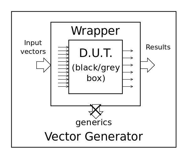
The early idea looks like this :
![]()
We have the D.U.T. integrated in the VG program/entity through a wrapper that transforms the bunch of wires into a couple of bland std_logic_vectors. Our vector algorithm won't care a bit about what's inside or how to interface to it, it's all just bits to read and write...
There is just one little big problem: the number of input and output bits is usually given by a generic parameter/number, but here it is provided "from the inside out" (or bottom-up) by the DUT/Wrapper, while VHDL "promotes" the reverse : generics enforce the top-bottom hierarchy and are provided by the top-level entity. Which can't guess in advance what's inside...
One could use configurations or even external generics but I want to keep the whole thing as lean and easy to use as possible. Ideally, the Wrapper would be generated automatically though at this stage, it's much faster and easier to do it by hand. Later I'll find how GHDL can help, as Tristan told me.
One natural solution is to change the hierarchy.
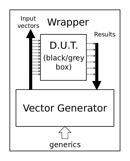
![]()
Now the wrapper encapsulates the whole thing, instead of being a mere translator/connector. A tiny advantage is that the DUT gets one level higher in the hierarchy, which will shorten the logs (a bit). There are two small wrinkles though:
- The wrapper should be as lean as possible, and easily computer-generated. If the VG is integrated, it adds complexity and any change in its interface (for control and reporting for example) will force a redesign of the wrapper and the wrapper generator...
- The order of inclusion matters. A lot. The wrapper has the burden of preserving it.
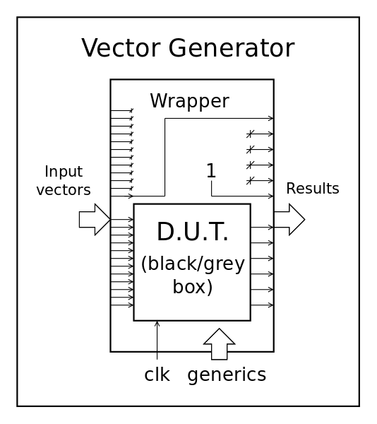
I return back to the first hierarchy with a twist : I let the system auto-configure itself through some simple tricks....
![]()
This system leaves the wrapper (and its generator) free from any consideration about the top level, by just routing a few wires here and there. The generics go in the right direction now and the vector generator could implement as many inputs and outputs as desired, and even more. The initial phase simply loops over the in and out vectors to determine the number of used bits, it doesn't take much time anyway, before it does the rest of the useful work.
Sounds like a good plan.
And here is the full source code for the wrapper of INC8 :-- A3Pv2.6/test2_INC8/Wrap_INC8.vhdl -- version dim. déc. 8 08:07:34 CET 2019 : forked from INC8_tb.vhdl -- -- Released under the GNU AGPLv3 license Library ieee; use ieee.std_logic_1164.all; Library work; use work.all; entity VG_Wrapper is generic ( VectGenWidthIn : integer := 9; VectGenWidthOut: integer := 10 ); port( VectIn : in std_logic_vector(VectGenWidthIn -1 downto 0); VectOut: out std_logic_vector(VectGenWidthOut-1 downto 0); VectClk: in std_logic ); end VG_Wrapper; architecture Wrap_INC8 of VG_Wrapper is begin dut: entity INC8 port map ( -- here we "wire" the unit to the Vector Generator ports: A => VectIn(7 downto 0), Y => VectOut(7 downto 0), V => VectOut(8) ); -- the wires for "autoconfig": VectOut(9) <= '1'; VectOut(VectGenWidthOut-1) <= VectIn(8); end Wrap_INC8;That's it !
As the name says, it's just a wrapper so nothing weird or complicated and it can easily be copy-pasted or generated by a program.
-
Winner scanner
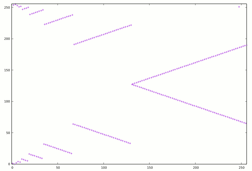
12/03/2019 at 04:14 • 10 comments![]()
The above picture shows the scanning pattern of the enhanced testbench for INC8. Not that it makes a big difference, since the scan is quite fast (1s on my i7) but for the ALU8, which lasts a few minutes at this moment, the 54% time saved will mean quite a lot...
It works well for the INC8 and the ALU because they rely on carry propagation (of some sort). The algorithm uses a dual loop (outer forward, inner backwards) that "hits" the powers of 2 sooner than a simple linear scan : the index 128 will be reached after 64 iterations, for example. Many "failure modes" appear on powers of two, or the index before (like : 127 and 128) so reaching them faster is good. This results in the "inverse sawtooth" pattern of the above picture.
This is boosted by another trick called "folding" that tests an index and its opposite. This creates the "horizontal mirror" of the picture. The resulting algorithm is a bit subtle but efficient and small:
-- 1743 cycles vs 3995 in linear mode !
procedure reverse_folding is
  variable j : integer := 1;  -- the current power of 2
  variable k : integer := 0;  -- the inferior limit for the reverse scan
  variable l : integer := 0;  -- the sub-loop counter for reverse scan
begin
  loop
    l := j;
    loop
      if (l < 128) then -- 128 appears 2x
        test_cycle(    l);
        test_cycle(255-l);
      end if;
      l := l-1;
      exit when l < k;
    end loop;
    k := j+1;
    j := j+j;
    exit when j > 128;
  end loop;
end reverse_folding;
We'll see soon enough if this cuts the run time of the ALU8 tests !
Well, guess what ?
For the thorough testing of the ALU8,
- 13.248.331 simulation cycles in 383s to check all the faults with linear scanning
- 1.121.723 cycles in 36s with reverse-folding !
so it's roughly a 10x increase in processing efficiency !
Upload: soon
20191205 :down to 34s and only 931.316 cycles with this dumb simple tweak : I swapped the SRI and SND ports !
I don't know how but I'll have to try some bit shufflings. However the search space is out of range : 16! = 20.922.789.888.000...
-
v2.4
12/01/2019 at 15:28 • 0 commentsI just uploaded A3Ptiles_v2.4_20191201.tgz and though it's a pretty modest update compared to the last archive (I added larger integers for the histograms and activity counters, plus a few features) the cumulative changes deserve a minor number increment ! So it's v2.4 already, and more features are brewing already : I am coding some files to import exclusion vectors from external files.
Stay tuned.
... and in read_xcl.tgz I prototyped the code that reads the "exclusion files".I could read the whole file into memory but I don't want to use more memory than required, particularly during initialisation. So I scan the file along with the list of gates. It's not the most direct/simple method but it is light on real resources and scalable if the DUT grows.
I'm about to include the mechanism inside the general system.
-
New feature : toggle counter
11/27/2019 at 03:52 • 0 commentsHere's a fun and easy one :
The newest feature simply counts how many times each gate's output changes value.
It might sound a bit silly for now but it was quick to implement and it will be very useful later when selecting the most appropriate implementation for the decoding logic. Some versions are "as fast as possible" and don't care about anything but giving the right result with the least logic depth as possible. Of course it generates a lot of logic activity and many spurious changes for nothing.
Other versions use a slower but more careful logic with latches to minimise the number of control lines to change. This reduces noises and power consumption with CMOS and FPGAs.
For now, there is no application but this will greatly help the design of the #YGREC8!
Of course I'll have to find a way to use 64 bits numbers with GHDL because I suppose that the current limit of 2³¹ cycles and toggles will be easy to exceed.
Whatever...
Stay tuned and watch for the latest upload in the files sections :-)
-
An unexpected turn with the histogram
11/24/2019 at 23:27 • 0 commentsI just uploaded A3Ptiles_v2.3_20191124.tgz but this is only an interim version.
The good part : I added a more complex circuit to test, the ALU8 has 83 gates, it is more rich and interesting than the INC8 unit (only 13 gates).
The bad part : I encounter cases that I didn't expect. By design, some gate configurations do not exist in the ALU8 and this creates a new situation. I need a way to explicitly tell the simulator that these cases don't occur, or modify the design to take these cases into account.
With this new situation, the system I created for INC8 (with a simple bash script) will not work at all because some cases will not be testable...
Anyway, the tool already proves its worth, because I focus on logic flaws I didn't see coming. The histogram is not just a gadget :-)
20191126 :
I tried one method to reduce the problem : I substitute the offending gates with a composite gate.
Most of the problems appear with AO1 : so I replaced them all (in the ALU8) with :
-- AO1 => Y := (A and B) or C;
architecture combi of ao1_combi is
  signal t : std_logic;
begin
 e_a: entity AND2 port map(A=>A, B=>B, Y=>t);
 e_o: entity OR2  port map(A=>C, B=>t, Y=>Y);
end combi;
It seems to solve most of the problems and the exhaustive fault injector can deal with fewer problems.
However some problems will always remains, "by design", the best example is with testbenches that only test a subset of the signals and decode into mutually-exclusive signals.
So I must add a mechanism to instruct the gate that some states are illegal...
What is the best way to transmit the information about the gates ?
- The easiest method is with a port. A std_logic_vector or string is an "optional" port, which can be left "open".
- A generic is another easy way to inject additional information with "default" value when not used.
Both of these methods create one problem : backwards compatibility is not preserved and they require the use of "if generate"s constructs to let the netlist source code run with the original simulator... But is it a real problem ?
Another method would be to use an external file with a list of gates-inputs to ignore. It's much more complicated though but opens the way to automatically generate the list from the histogram.
It seems that both methods are complementary so I'll have to implement them both...
I have chosen the generics mechanism to provide an inline "exclusion list", with an unbounded std_logic_vector as parameter. Every 'X' becomes an entry to exclude. The list can be empty, of course. In the first simple test, here is one example:
x5: entity xor3  generic map(exclude=> "X-X-X-X-")
              port map(A => D, B=>G, C=>H, Y=>Y );
Backwards compatibility is broken but it could be solved with a "if-generate" if ever needed.
Now I work on making sure everything works well like before.
-
Modes of operation
11/22/2019 at 15:45 • 0 commentsSuppose, for the sake of argument, that you want to create a digital silicon chip, for example. The exciting ASIC world is calling your name so your RTL code is tested, formally verified, simulated, cosimulated, and finally synthesised.
At that point, you would want to ensure the synthesiser did not poo-poo your neat system so you can re-simulate the mapped netlist, using the fast mode of this library. Or you can simply write and pre-map some modules in this low-level dialect, as I do.
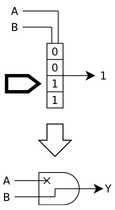
Fast mode
In this mode, each logic gate is replaced by a lookup table of the appropriate size.
![]()
Fast mode doesn't care much about meta-values, "if it's not 1, it's 0" to speed things up. Be ready to break your code, and in the process, uncover potential troubles with badly initialised registers (for example, and if your synthesiser didn't warn you enough before).
Now your code works in after-synthesis. But it's only the beginning of the end of the road because going from the virtual world to the real world implies a crazy shift in methods and focus, and I'm not even talking about place/route/retiming and other niceties... Because here, we're out of the comfortable walled garden of FPGAworld, where they sell you "Known Good Dice" that will behave exactly according to the specifications of the datasheet. No, the factory will deliver dice, some of them might even work !
How would you know which are good ? Run a program, for example, and see if it returns the expected good value : that's a valid idea but it can work only if the die is totally connected to the outside world... and this is costly, particularly if the die is DOA ! The usual solution is to connect only a few pins to a test rig, power up, inject signals and check the results. If the circuit looks like it's not dead and passes enough tests, it can then be packaged for further thorough tests.
Trace mode
One of the approaches for testing the chip with only a few pins is to make it run some sort of internally-generated sequence or even program that will exercise all (or most) units in the chip. It's called "BIST" for Built-In Self-Test and it must be designed along with the chip itself (remember the "Design For Test" DFT methodology they bore you with ?) so you're not caught with untestable units at the last moment.
So the chip must be designed in advance to allow self-testing, which means you must synthesise often and run/simulate the BIST to ensure that ALL the gates are covered. This scenario is covered by the second mode of the library: trace mode that works with both normal and meta values. When one meta-value 'L' or 'H' is found at the input, the output will be a valid meta-value, so it propagates a meta-state in the logic cone. You can either set an input pin to meta, or select one input combination to output the corresponding metavalue. All the computations should be performed correctly, right ? At least you should observe a number of meta-values at the output to see which input or gate affects which output bit.
Hopefully, this should help you design, adapt, refine and select your BIST methodology.
![]()
For now you can only select one bit to "meta-ise" but it shouldn't be too hard to brute-force a small design, you can even run multiple GHDL instances in parallel, though that's only the beginning.
Flip/Alteration mode
Once you have selected your BIST method and built your test vectors, you need to test them exhaustively. You synthesise again and now you simulate over and over, with each iteration altering a different bit in the LUT of all the gates. Each time, one bit is flipped, which might subtly change the function of the gate and the whole circuit... Meta-informations are propagated like with the trace mode but no new meta-value is injected. However the change of any gate should result in at least one invalid result at the output.
![]()
This is the most useful mode so far because it simulates the imperfect world. Furthermore, an exhaustive test might not be really expensive because the test time grows with the number of gates (times inputs per gate), not the number of available states. And as stated before, you can run as many parallel instances of GHDL as you like !
Probe mode
BIST is great but there might not be the required size or time or even possibility to let the chip test itself. In this case, you'll have to inject the test vectors all by yourself. And this time, time is even more critical because 1) testing time is expensive (you don't want to spend more than a second testing each chip, on a machine you pay by the hour 2) bandwidth is limited by the few pins and you can't observe the circuit running at full speed. So you have to select the fewest test vectors possible that still ensure the circuit is (sufficiently) functional. You can't let the circuit itself generate hundreds of millions of vectors with 1% chance of hitting any possible new fault : each additional vector must hit at least one fault that was not covered by the last vectors.
As stated before, the maximum theoretical number of test vectors is the total number of gate input states. If you have 1K gates with 3 inputs each, that's 8K vectors, however many can be fused because they are either redundant or also test neighbour gates. OTOH it's not easy to get the optimal set of test vectors but there are many heuristics that help reduce the number anyway.
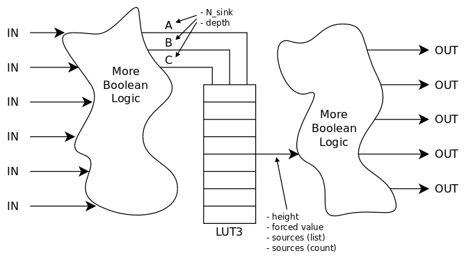
![]()
But before we can build or design the test vectors, whatever the strategy, we need to have the full netlist of the design. We already have a gatelist from the previous modes and they control the outputs at will, though yet under the control of the LUT. It takes little effort to decouple the input from the output and selectively control the output value while also logging and processing the activity on the inputs. That's the probe mode which requires a different running environment : instead of simulating the design with actual test vectors, the netlist extractor processes the gates individually. It's a conscious choice to not examine the RTL source file itself, but run it because you never know, there would be sub-units and all kinds of non-obvious things, in case we don't get a flat netlist. We can access each gate individually and that's all we need yet.
![]()
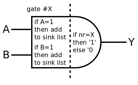
Each time an input changes on each gate, the output value is evaluated by a function whose behaviour changes according to the mode. In the probe mode, the value is checked and added to a log, while the output changes to signal itself to the other gates. In the above diagram:
- The output is set only if the gate is selected (its number matches the selected gate number), otherwise it's reset to 0. Thus all the sinks to this gate will receive '1' only from this gate and they know they are connected to it.
- Each input is read and if the value '1' is found, then the number of the current gate is added to the list of sinks of the emitting gate.
Given the list of all the gates, it's easy to scan it and run a test for each of the gates.
Now, it's not as easy in practice and the implementation has some tweaks and tricks.
- You can't change the gate's output at will. There is no way to explicitly send/trigger an event to refresh the gates. You have to do it implicitly by changing the value of the inputs. I have allocated 2 values of the type std_logic_value for this purpose (for the output to change and force the refresh of the output) : 'U' and 'X'. This also means that the output will be either 'X' or 'U' (following the current cycle) and not '0' as in the example.
- 'U' and 'X' are used but we can still use 7 other values from std_logic_vector ! So we can test simultaneously 7 gates with the values '1', '0', 'L', 'H', 'W', 'Z' and '-'. This speeds up things a bit. Unfortunately, the netlist can't be extracted all at once because std_logic has only 9 values and we can't re-cast the DUT (that would have been too easy, right ?)
- The DUT must be inside a sort of wrapper, which I can't yet automatically design but Tristan Gingold told me there is a way, using methods that are not (yet) familiar to me. Time will tell but for now, I'm doing it by hand.
The probe mode is used to extract the netlist, which is then used to generate test vectors. The DUT is then run again in Flip or Trace mode to verify the coverage of each vector : each vector tests at least one gate in a given configuration throughout the whole logic depth for the input to give an observable output and these gates can be crossed out of the list of configurations to check/test with the following vectors.
TODO
Now that we can peek into every net and gate, it is possible to count how many times or often the states changes. This is useful to evaluate the power savings of a given architecture or estimate how much the circuit will draw from dynamic vs static current.
The "toggle" mode should be implemented someday...
-
The way to v2.3
11/21/2019 at 00:56 • 0 commentsHopefully, v3 would implement some sort of ATVG but this is a complex algorithm with several steps, the first of them is to extract the netlist from the "blackbox" of the DUT (Design Under Test). The current version 2.2 is not yet able to do that and the chosen approach is to not analyse the DUT's file themselves, but only use "functional/behaviour" data obtained from 1) running the DUT 2) extracting and injecting information at the inputs/outputs and the gates themselves.
To extract the netlist, I don't intend to use simulator-provided internal feature. I have chosen the following "greybox" method :
- list all the gates, add inputs and outputs
- exclude all the LUT2 and LUT1 gates (inverters, buffers, GND, VCC) because they contribute no useful information
- Clear all the larger LUTs (with 2 and 3 inputs), set LUT2s as pass-through
- For each of the inputs and gates, select 7 of them and assign to their output the value '0', '1', 'W', 'Z', 'L', 'H' or '-' (so we can test 7 gates simultaneously)
- Send "all 'U' " then "all 'X' " values at the inputs to force the refresh of all the gates => these values will propagate (pass) through the whole design. However, the gates that have a different value will see their value propagated to the inputs of other "sink" gates.
- Scan all the gates and check their histogram to see which value they receive at their output. If one of the values "01WZLH-" is received, add the n° of the current gate to the list of "sinks" of the sending gate (there would be an array to store this info, which is refreshed for every iteration of the algorithm)
- After all the inputs and gates are scanned, each of them should have a list of their sources and sinks gates.
The current code requires many modifications to permit this : for example, the lookup functions in the gates will be deeply altered and the global list of gates will have to hold much more information, in a better structured way. I also want to get rid of the the various architectures of gates and merge some code, which will make the library easier to use and probably even smaller. Hopefully I can find an easy yet efficient way to avoid having the "trace" architecture.
And of course, I must add the ALU8 as a 3rd example :-)
Let's do it...
Here it is ! A3Ptiles_v2.3_20191121.tgzIt's only a preliminary version where there is only a single architecture, more upgrades will follow.
VHDL library for gate-level verification
Collection of ASIC cells and ProASIC3 "tiles" in VHDL so I can design and verify optimised code without the proprietary libraries