The whole project is divided into three parts :
The power supply which requires 18-24V input and produces all the necessary voltages : 5V , 3.3V and 150V .
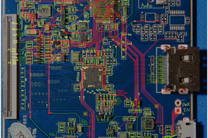
Controller - a board containing the preamplifier and the STM32F407 chip , which is responsible for sampling the input , calculating FFT , calculating the logarithm of the signal amplitude , producing 24 PWM signals and the blanking signal . The controller has two modes : stereo mode in which signals from each channels are transformed and calculated independently . In stereo mode each IN9 board displays one channel. In the mono mode signals are added an the FFT is calculated for the sum of the channels . Then the result is displayed using both boards as one , 24 channel display. The controller board contains a microphone preamplifier , so the signal can be either connected to the device from the "line-out" output or picked with the built in microphone
Two IN9 boards. Each board contains 12 constant-current drivers for the neon tubes. The outputs of the drivers can be switched off synchronously with a signal from the controller . I found out , that it is necessary to power the IN9 tubes with puled current if one wants to avoid "floating discharge" in the tubes.
The analyzer in the mono mode :
The analyzer in the stereo mode :
 Jared Sanson
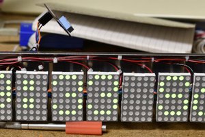
 Bharbour
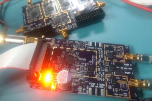
 Jon Klein
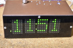
This is a nice project and I like to build one. But when looking over the Gerber and pictures I see no way I can solder the coils in the power supply without a re-flow oven. Since redrawing the schematics from the PDF might introduce errors by me, I would like to ask if you can share the original schematic files, that way I only have to adjust the component layout on the board layout.