 Laser Developer
The Unruly specifications: Make it hack worthy
The Unruly is not just a crazy hack but is also a serious educational tool with lots of capabilities added to allow for experimentation. Here's the Unruly feature list in no particular order:
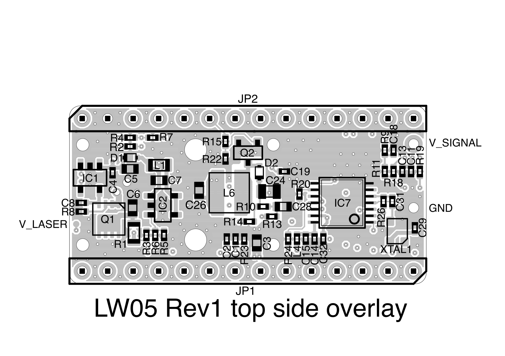
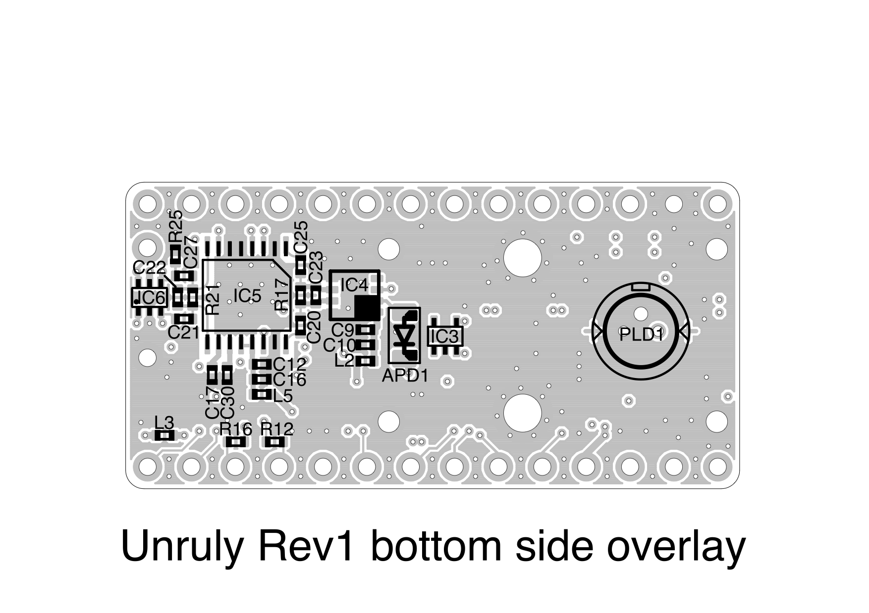
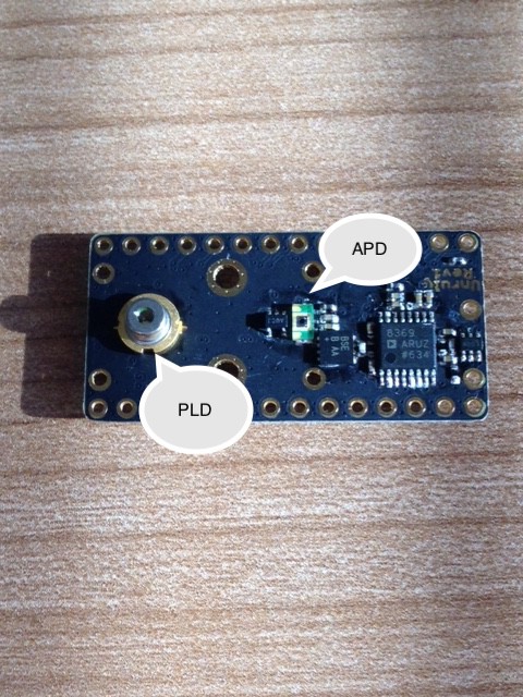
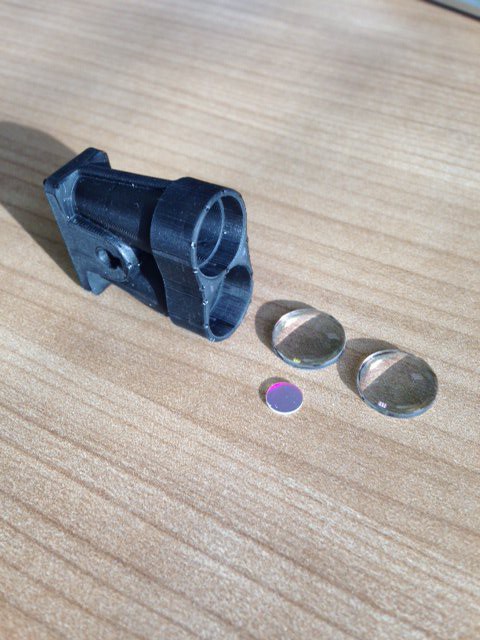
- The Unruly is a time-of-flight LiDAR that uses a pulsed laser diode (PLD) to generate a flash of light, an avalanche photodiode (APD) to detect the return signals and a high speed timer (TDC) to measure the return time.
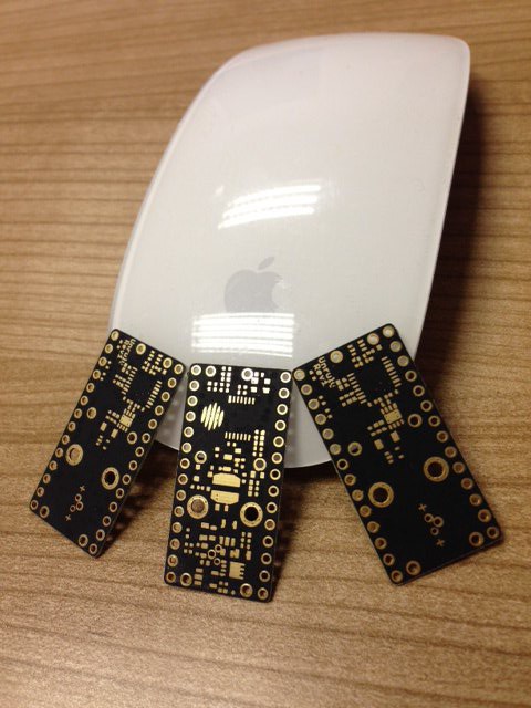
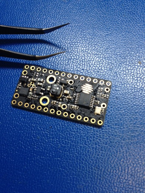
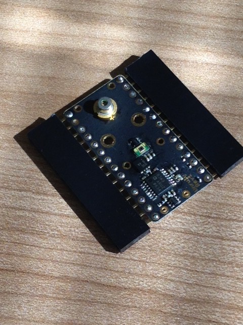
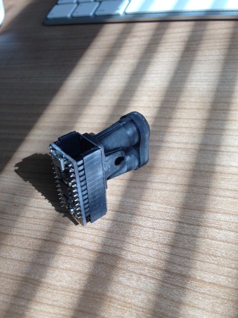
- The total circuit board area is one square inch.
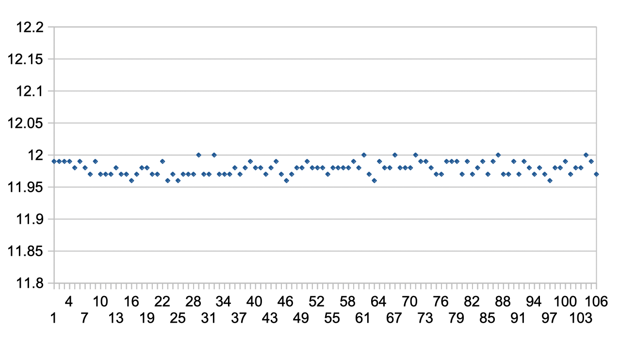
- The measuring range can be adjusted to over 100m on natural surfaces and 250m on reflective surfaces, outdoors in bright sunlight.
- The resolution can be configured down to 1 cm.
- The measuring rate is up to 1000 readings per second or maybe more ;).
- The laser power, pulse width and eye safety ratings are all under software control and can be set to Class 1, Class 1M or Class 3R to suit the application.
- The APD detector can be adjusted under software control to operate at optimum sensitivity taking into account temperature and ambient conditions.
- The amplifier gain can be adjusted under software control to achieve the best SNR (signal-to-noise ratio).
- The detection threshold can be adjusted under software control to set the false return error rate.
- Up to five different target returns can be measured on each laser shot.
- The total power consumption is less than 0.5 W.
- USB, serial and I2C communications are available at the same time.
- Two servo driver ports are available to control scanning (https://youtu.be/IirAJO5H0yI).
- A digital I/O for alarms or other purposes is available.
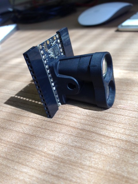
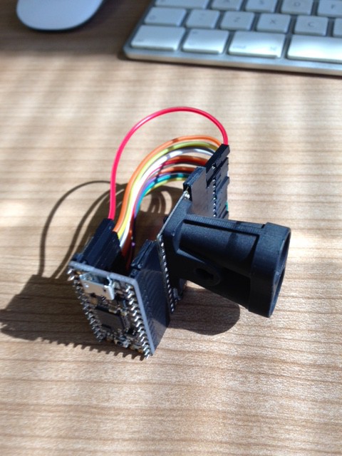
- Mechanical parts are 3D printable.
- EMC emissions are low enough for use with RTK and GPS systems without interference.
- EMC immunity is high enough to allow for use with BLE, WiFi, LoRa or other radios in close proximity (still to be tested).
The Unruly use of open source hardware: ItsyBitsy M4 Express
The Unruly uses existing open source hardware as a starting point, the Adafruit ItsyBitsy M4 Express. This is a small microcontroller board with a SAMD51 processor, extra flash memory and almost nothing else. Why, you are asking, have you chosen such a basic controller board to manage the complicated hardware of a LiDAR? Well, my wife likes how small it is and it has a cute name. Of course it helps that the SAMD51 runs at 120MHz and has a bunch of really interesting peripherals.

The Unruly use of open source software: CircuitPython
Another reason for choosing the ItsyBitsy M4 Express board is that it can run a version of the programming language Python called CircuitPython. This is by far the least likely language to be used in a high speed embedded system, especially one that needs to work at the speed of light. Python is an interpreted, high level language that manages variables and memory in a vague, non-specific way. There are only a few APIs and these do stuff that is no use to a LiDAR.
But CircuitPython is easy to write, easy to read and can be programmed without an IDE by using a basic text editor. This seems like a good enough reason to use it.


 Ben Brown
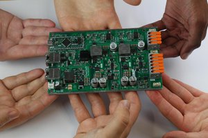
 Jean Alinei
 Illinois Space Society AV
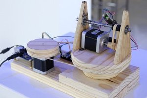
 Brendan Ardagh
Hi,
Is there any github repo for this project? I'm trying to build a LiDAR by myself. It will be a good start if I would get a github repo for this project.