Close
0%
0%

TV-B-On(the box)

The thing you need when your TV remote power button fails.

Similar projects worth following
A while back the power button on my remote started to fail. It's become harder to get it to send the IR code to turn on the TV. The contact is likely dirty but didn't want to risk destroying the remote by the extreme violence it that would be required to get the shell open.

Frustrated, I threw together a quick and dirty solution using one of my Atmega328P Target boards, a AA battery pack, an IR LED, a transistor, a push button, an AMS sample box I had laying around, and the requisite wiring and rubber band to hold it all together. A bit on the crude side, but it works!

I'm planning to make a more-refined version.

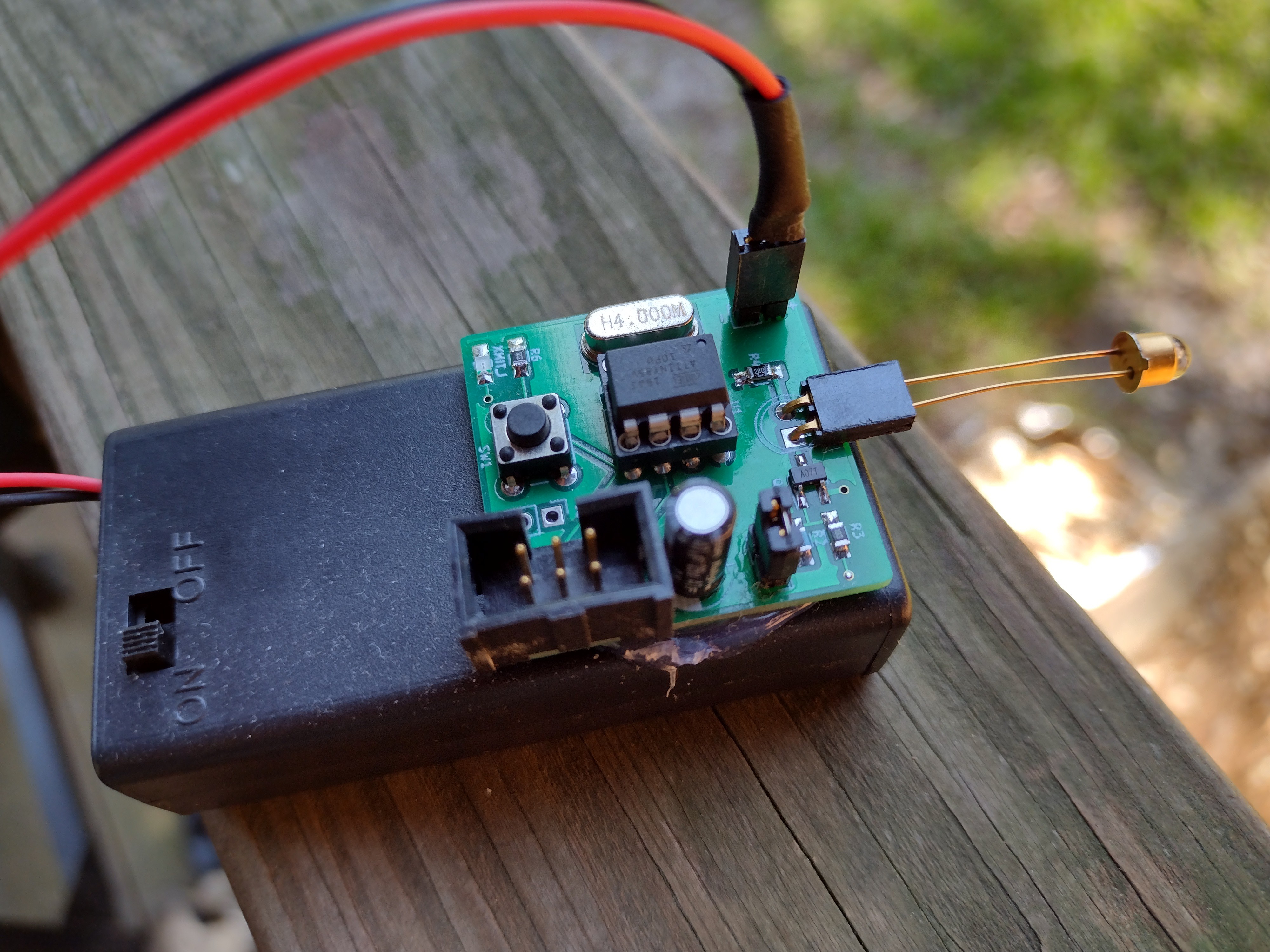
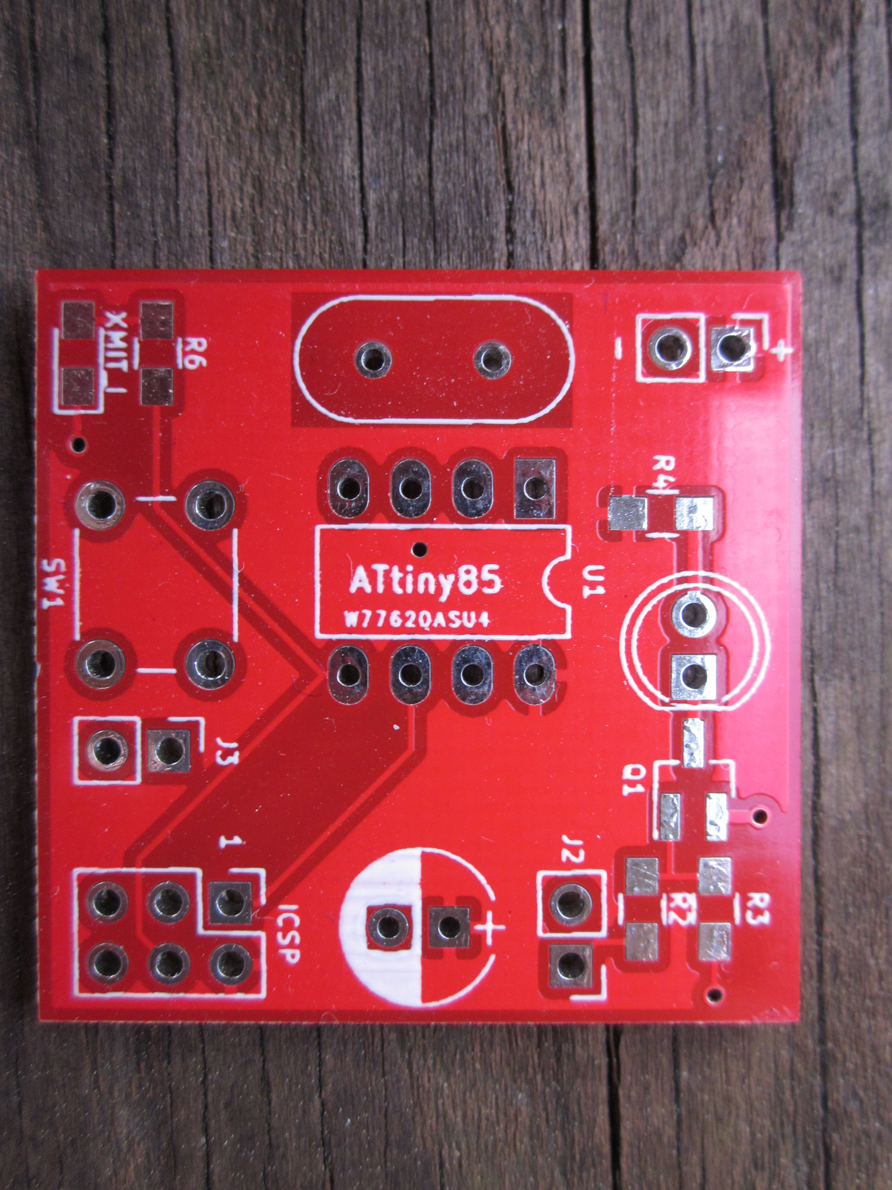
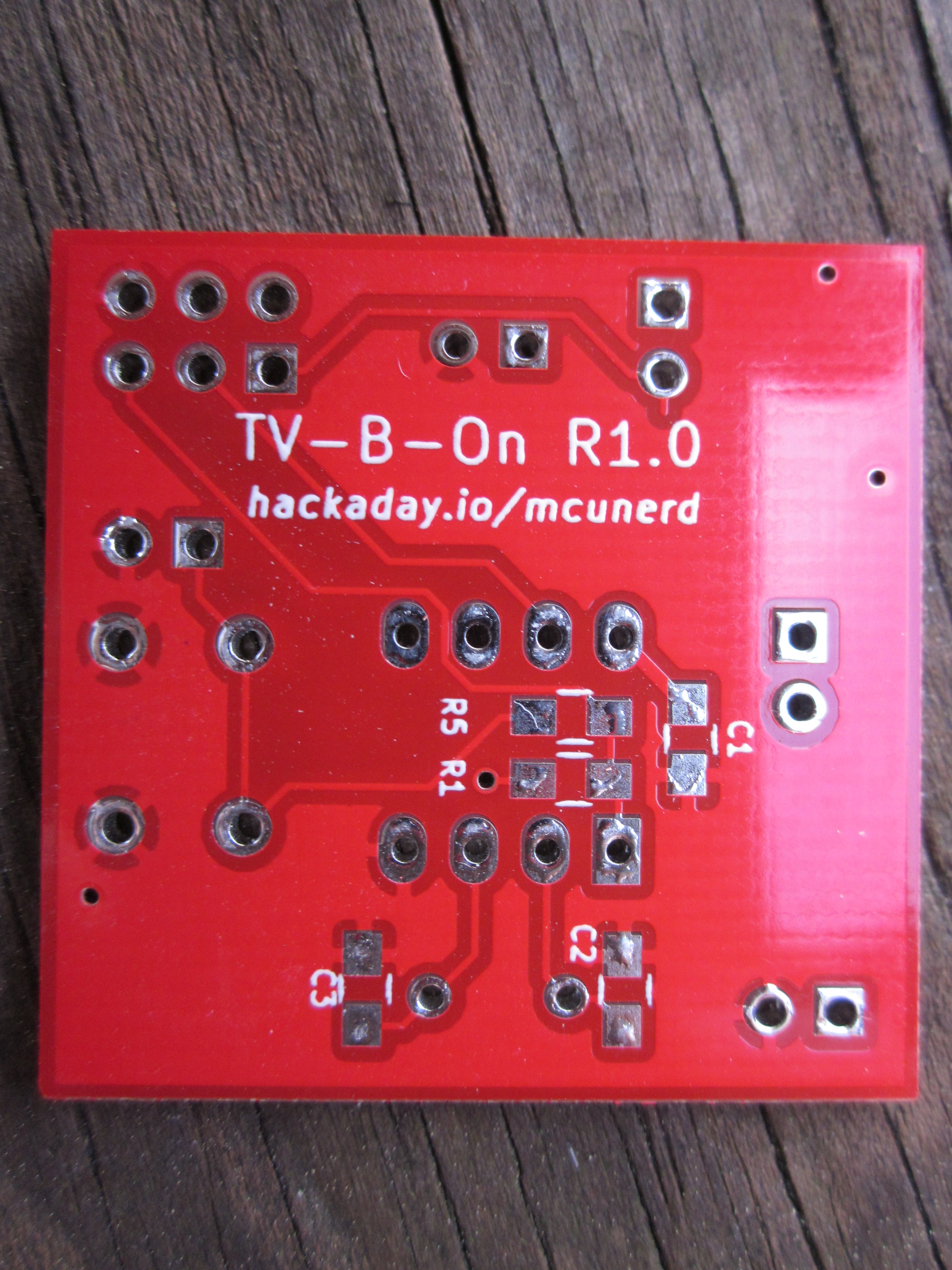
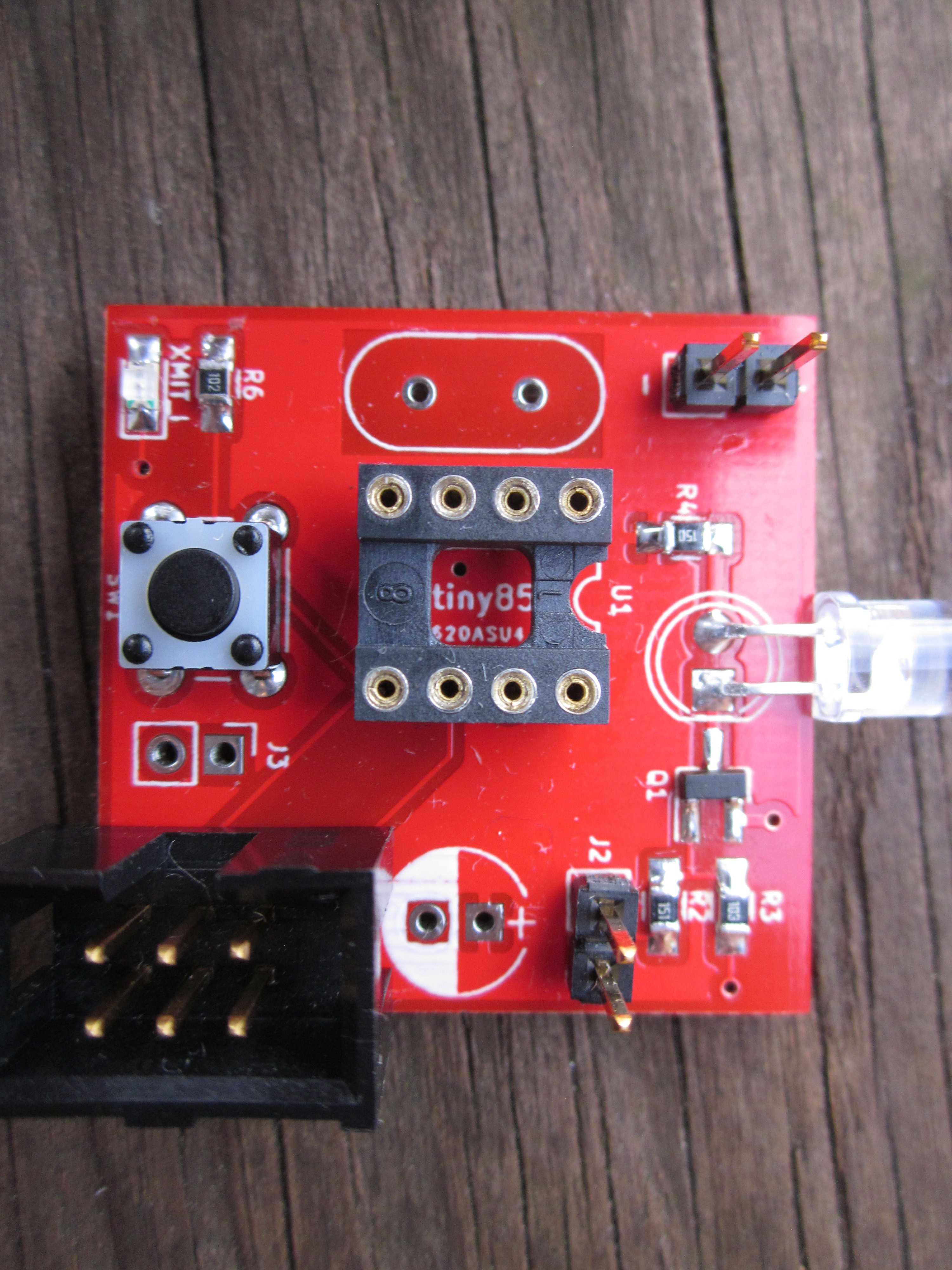
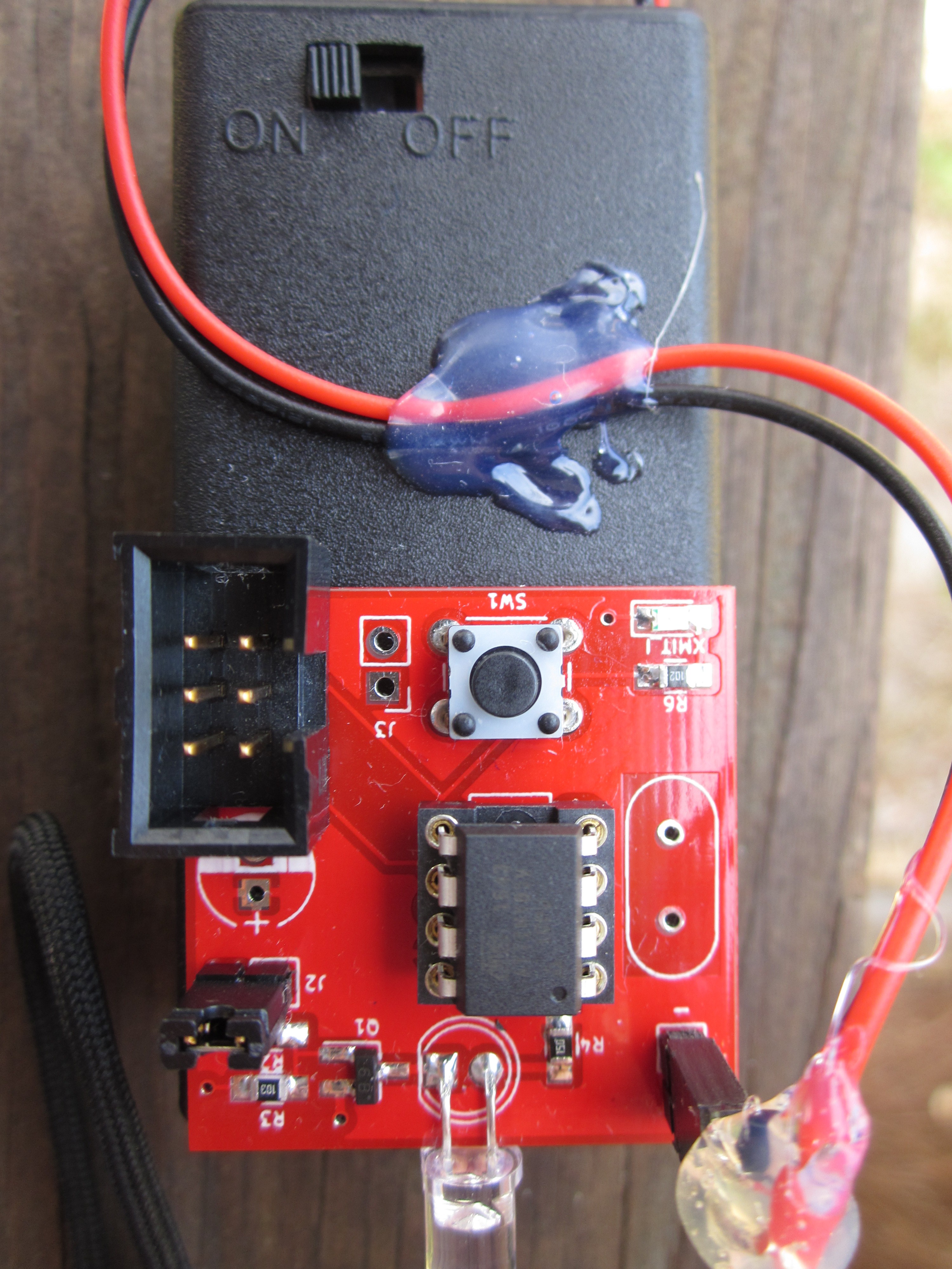
The current version (the Attiny85 one is a bit more refined than my original, crude thrown together version.  It's designed to send the IR code on power on/reset and then go in a very low power sleep mode until the reset push button switch is pressed again.  An on-board push button switch or an external  push button switch wired to the J3 pin header can be used.  I added jumper J2 to allow the IR LED to be disconnected when uploading code to the Attiny85 to eliminate the risk of damaging the IR LED from being driven at too-high a duty cycle (it's perhaps a bit overkill. I also added an indicator LED to show when it's transmitting (surprisingly useful for debuting.)  I chose a red LED for the indicator due to the relatively low forward voltage it needs.

On the parts list there are some different values listed vs what's shown on the KiCad schematic.  This was due to me making some value adjustments after doing the schematic, and thus the values listed on the parts list are current. NOTE: The R2 and R4 values are based on the board being powered by 2xAA batteries. If you plan to use a higher voltage, the values may need to be increased.

t85irNEC.zip

sample code for transmitting NEC IR codes

x-zip-compressed - 6.80 kB - 07/03/2019 at 17:18

Download

t85irTVonDemo.zip

Code that I used to turn on my Insignia TV, of course not the finished product.

x-zip-compressed - 6.63 kB - 07/02/2019 at 22:24

Download

TV-B-On.zip

TV-B-On KiCad board files

x-zip-compressed - 104.74 kB - 04/03/2019 at 19:14

Download

  • 2 × 0805 10K resistor (R1 and R3)
  • 1 × 0805 150 ohm resistor(R2)
  • 2 × .100" 2 pin pin headers (J1 and J2, if soldering directly to the power header only 1 is needed) Batteries and Battery Accessories / Battery Holders, Snaps and Contacts
  • 1 × 6mm thu-hole 4-pin push button (not needed if using an external push button)
  • 1 × .100" 2x3 pin header or shrouded pin header (for ICSP, optional if not programming the attiny on the board)

View all 19 components

  • Swapping out the BJT transistor for a MOSFET, initial fail but got it working after some tweaking. A tale of partial success.

    mcu_nerd06/15/2023 at 13:36 0 comments

    I got some inexpensive logic-level MOSFETs in, model AO3400-SOT23-3L. I assembled a board (shown below) with the MOSFET, programmed the ATtiny85, pointed it at a TV. Nothing. I added a capacitor to deal with the high-current pulses. Nope.  I then held it right next to the IR receiver on the TV. It worked. 


    So what was going on? Well, it deals with how MOSFETs work.  A MOSFET acts as a capacitor.  Once a voltage is applied to the gate of a MOSFET, it charges up as a capacitor. It also takes time to discharge when the voltage is brought down to ground.  How much current that is source/sunk determines the charge/discharge speed and thus how quickly a MOSFET fully turns on/off. 

    Switching at 38KHz on the surface doesn't sound problematic with a small MOSFET until you consider that I was using a 1 percent duty cycle, resulting in a pulse width of around .263 microseconds.  It apparently wasn't enough time for the MOFET to fully switch on with the current I was providing to the gate.  Upping the duty cycle to 10 percent, made a dramatic improvement.  The downside of upping the duty cycle is that many IR LEDs have a max safe duty cycle of 1% for high current pulses.  I would love to measure and see this, but I would need an oscilloscope, which I don't have.

     I'm limited when it comes to increasing current as the recommended source/sink max current for the ATiny85 is 20 mA. I could try upping it to the absolute maximum listed in the datasheet of 40mA but that does risk stability.   A better solution would be to implement a gate driver either using a dedicated chip or using discrete components, but I would have to be careful about increasing standby current consumption to keep the excellent battery life.

    Running it with a 10 percent duty cycle based on initial testing does appear to beat out boards using a BJT at the same duty cycle.

    In conclusion, everything is a tradeoff.  I got rid of the voltage drop of the BJT but in turn had to deal with the problems with a slower switching speed due to lacking a proper gate driver.

  • Having some more fun

    mcu_nerd03/08/2023 at 15:26 0 comments

    CAUTION: don't mess around with mains, unless you know what you're doing. Please excuse the less than stellar production quality of the video, wanted to  make a quick video at the bottom showing that it does work as per the contest rules.  I had some stuff laying around, including a small solid state relay (SSR),  so I decided to make a remote controlled light for the fun of it.  The little SSR only gets slightly warm with a 40 watt incandescent bulb (the SSR is rated for a max of 1 amp.)

    In other related news, I've ordered a proper MOSFET that should work well at a low voltage, allowing me to crank the power to 11, to see if that problematic TV will play nice with an IR LED putting out around 800mA of peak current. I did try using more cells to boost peak current output a bit (to around 400mA or so) a few weeks ago, but even that was still not enough to get that problematic TV to behave.

    It also does not seem to make a great deal of difference (in my limited testing) of either using a crystal vs. using the internal oscillator. Still, it doesn't cost much to get a considerable boost in stability an accuracy.

  • I made a cat repellant device to keep them away from places they shouldn't go, it worked (kinda)

    mcu_nerd02/13/2023 at 23:08 0 comments

    I plan to do a separate project page for the alarm device. Since I did use the TV-B-On to trigger it, I figured I would post a test of it here.  I saw a cat (who I'm good friends with) in the garden, a place she shouldn't be. I placed the alarm device near to her. the results:

    She was far more curious about it vs. being afraid of it. So much so, that she came out of the fenced in garden area to check it out. The root reason I made the alarm was to scare away a cat (not the one in the video above) that likes to sit under the bird feeder and tries to catch birds.

  • Fell into a trap, made some interesting findings, and building up a collection of TV-B-On's from testing

    mcu_nerd02/04/2023 at 05:53 0 comments

    It's been another busy day of building and testing. 

    A minor trap is sprung

    I started off with hooking up my logic analyzer to one of my TV-B-On's and firing up Pulseview.  I soon noticed that there were some really long pulses, as shown below.

      I played around a bit more, I noticed the longer I held the push button (that pulls down the reset pin, and thus puts the ATTiny85 into reset), the longer the pulse. I pulled out my multimeter and checked the voltage with the push button held down, and sure enough the voltage of the pin of interest floats a bit when the microcontroller is held into reset.  It's not an issue though as there is a 10K pull down resistor of the base of the transistor to prevent the IR LED from triggering from things like this.  This touches on a key limitation of logic analyzers: they can only show you "high" or "low" vs. showing an actual voltage.  An oscilloscope would have quickly showed what was happening.  I hope to get an oscilloscope one of these days, I've been hesitant to dig down and shell out a few $100.

    A bit larger trap spawns


    But the logic analyzer wasn't done with me yet.  I also wanted to see the duty-cycle of the 38KHz carrier. I set the sample rate to 3MHz Correction note: I initially set the sample rate to 1MHz and later on to 3MHz, the screenshot below is from when it was initially set to a 1MHz sample rate, thinking that would be more than good enough temporal resolution. Here's what I got: 

    I was getting what appeared to indicate that the PWM duty cycle was glichy, and in the case of setting an extremely low duty-cycle, was getting what seemed to be outright missing pulses.  I figured I must have done something wrong in my code.  I checked the datasheet, looked online at various PWM examples, and became frustrated. I got the odd idea of cranking up the sampling rate to 24MHz.  Things now looked as expected. Nothing major in terms of glitches or missing pulses.  Setting the sampling rate to 3MHz and zooming in to the point of showing the actual sample points shows what was happening (recommend click on the screenshot to enlarge):

    Ya, there's actually not a lot of temporal resolution to accurately capture a pulse at a 3MHz sampling rate in this case, or even a guarantee that all pulses will be captured as in the case of a very low duty-cycle.  Basic math time. A sampling rate of 3MHz, means that a sample will be taken every 1/3 of a microsecond.  A 38KHz signal has a period of about 26.316 microseconds.  At a 1 percent duty cycle, the pulse width will be around .263 microseconds. Yea, that's a bit problematic.

    Here's a result of doing a re capture with upping the sampling rate to 24MHz:

    That looks a bit more sufficient in terms of sampling. A 24MHz sampling rate means that a sample will be taken every .0416667 or so microseconds, so in this case no more worries about failing to capture some pulses.

    Revelations from additional testing and experimentation

    I assembled another TV-B-On, using a 5.6 ohm resistor for the IR LED in place of the 15 ohm resistor value I have been using, giving a considerable boost in current to around 150 mA or a little bit more depending on voltage and the particular IR LED model used.  I plan to boost power a bit more, but I'm probably starting to push the limits of the NPN transistor I'm using and need to switch over to a MOSFET that has low resistance at a low gate voltage.


    Onto testing.  At a 1% duty cycle or so, the boosted current didn't seem to provide much in terms of improvement vs. just sticking to the 15 ohm resistor and using a 10% duty cycle.  I could try also boosting the duty cycle and could probably safely get away with doing that as I'm not pulling anywhere close to the rated peak current of the LEDs used.

    I learned more about the quirkiness of the TV in the other room that I talked about in the previous log. Further testing from today showed...

    Read more »

  • With the entry into the 2023 Low Power Challenge, I've revisited things and have found some refinement is needed

    mcu_nerd02/03/2023 at 04:42 0 comments

    First things first, I'll post the current it draws from 2 AA batteries (rechargeables in my case) for 99%+ of the time when it's not being used as one of the contest rules was to include power measurements:

    Using around a tenth of a microamp, means that the self-discharge of the batteries could very well be the limiting factor.  The one that I regularly use for my living room TV has been running on 2, AA low-self discharge NiMh cells for over 2 years without recharging them.

    I've assembled another board and have done some rather testing. The testing was a bit on the subjective side of things, but I've found some issues.  A TV in another room that uses the same NEC protocol and uses the same code to turn the TV on/off that the living room TV uses, did not play so nicely with TV-B-On.  It worked intermittently at best.  I did some more research and some places state a recommended duty cycle of 1/4 to 1/3. Up until this point, I've been using a 10% duty cycle.  That helped some, but it was still a bit inconsistent.

    I also thought about improving the accuracy of the 38KHz signal.  The timer I've used to generate the 38KHz signal ATTiny85 uses the system clock. Up until this point, I've set the ATTiny85 to use the internal RC oscillator as its clock source for the system clock. Let's take a look of the accuracy specs of that:

    Yea, not exactly great accuracy.  You can dial things in better either by changing the value in the OSCCAL register or by tweaking values used to set up the timer.  The problems with doing this are two-fold.  It has to be done on a chip by chip basis and the frequency varies depending on the supply voltage. It's a very finicky thing to do. The latter issue could possibly be mitigated by characterizing each chip on a range of voltage points and finding the best settings at those particular points, using the ADC to measure current supply voltage, and based on the ADC reading, select to closest set of optimal settings, but that's going down quite a rabbit hole.  I did take some frequency measurements and did indeed find the signal was off anywhere from a hundred or so Hz to over a KHz or more.

    There is a far better, simpler solution: use a freaking crystal.  For a crystal frequency, I selected 4MHz. As to why I selected 4MHz vs. 8MHz which I have been using for the RC oscillator is for staying well within the recommended max frequency in respect to supply voltage.  Running at 8MHz is perhaps running on the edge of things, especially when using nominal 1.2V NiMh cells, and double so when the voltage drops as the cells discharge.  I have placed an order for some 8MHz crystals and could try it, although it's probably unnecessary.  I took some frequency measurements using a 4MHz crystal, at it was almost bang-on 38KHz. Of course, fuse settings and program code had to be altered, but that didn't take much effort of time to do.  I'm glad I made the provision to add a crystal when I designed the board, so a re-spin wasn't needed. I did re-validated the current draw when powered down after switching over to using the crystal, and there was no noticeable change.

    Another thing to note: In most cases I tend to shy away from using a crystal with the ATTiny85.  In most cases, the ATTiny85 has only 5 I/O pins to start with. Using a crystal, takes up 2 of those pins, leave only 3 pins for I/O.  That wasn't a problem in this application, but that can be a major limitation.  It would be really nice if Microchip would make a version of the ATTiny85 with a more accurate internal oscillator.

    After switching over to the crystal, there did seem to be an improvement, but things still weren't quite right.  Recharging the batteries resulted in a further improvement, but things can still be a little inconsistent.


    My next course of action is more power! That is, to drive a bit more current though the IR LED. As it stands right now, depending...

    Read more »

  • The fustrating journey of getting Lego power functions IR to work

    mcu_nerd01/29/2020 at 16:35 0 comments

    I had my Lego train out(that uses Lego power functions) and wanted to try controlling it using my TV-B-On remote.  I did a bit of googling and found the datasheet on the IR protocol.  I whipped up something quick and dirty. It didn't work.  What was it? Was it the fact that I didn't send the code 5 times as per the specification?  Do I actually need to count out 6 IR pulses (the stop/start bit, high and low bits all start with 6 IR pulses, it's just the delay after that differentiates them?) Do I need the send the 16 bits LSB first?

    I first grabbed my Arduino Uno and uploaded the IRdump sketch from IRremote library, but the output wasn't too useful in this instance.  I then pulled out my inexpensive logic analyzer and opened Pulseview(Sigrock.) I then proceeded down the rabbit hole of getting my code to count out exactly 6 IR pulses. Still not working.  I then tried sending the 16 bits LSB first. Nope. I also tried sending the code 5 times as per the specification and still nothing.  While I was at it, I hooked up my signal analyzer through a 3 pin IR receiver and discovered that per an IR burst it just shows up as one burst (the 6 IR pulses just shows up as a single large pulse.)  So it wasn't critical to count out 6 IR pulses.

    I then decided to find an Arduino Lego PF library, make up a sketch of the code that I was trying to send on my TV-B-On on my Uno, hook that up to my logic analyzer and examine the output. I found a working library here.  A ran everything and decoded the bits (the PWM decoder in Pulseview made it easy to tell the 0,1, and stop/start bits apart.)  I shortly discovered the problem. The problem was with the 4th nibble, the LRC data.  The datasheet states that the LRC is calculated by doing an xor operation on the first three numbers and the number 0xf.  I assumed that doing an xor operation on 4 numbers would work just like two numbers, is there is a single one bit in a particular position, the result is one, overwise it's zero like shown below:

    1111
    0100
    1000
    1000
    
    result
    0011

    The bits that I decoded from the known working code however gave me 1011 instead. I looked up the rules for more than 2 numbers and found this from this website "To find each bit of XOR just calculate number of 1’s in the corresponding bits. If it is even or zero then that XOR’ed bit is 0. If it is odd then that XOR’ed bit is 1."  I made the correction to my code and it worked.  I did find out for the mode I was using at the time at least that I don't need to send the code 5 times with the specified delays per the datasheet.   

    Here's a screenshot from pulseview of the generated output and I've also included my code that's still very much a work in progress.

    EDIT: I've also included the capture both at the pin and thru an IR receiver.  I'm not sure how to easily decode the capture thru the IR receiver.

    #include <avr/io.h>
    #include <avr/interrupt.h>
    #define F_CPU 8000000UL //8 MHz
    #include <util/delay.h>
    void start_stop_bit(void);
    void high_bit(void);
    void low_bit(void);
    void send_message(unsigned int mess);
    void send_combopwm(char nib2, char nib3, char nib1);//blue,red,channel
    void send_singleoutput(char mode, char output, char nib3, char nib1);//mode
    //zero for red channel 1 for blue, command,channel
    volatile int count=0;
    
    
    #define PWM_FLT 0x0
    #define PWM_FWD1 0x1
    #define PWM_FWD2 0x2
    #define PWM_FWD3 0x3
    #define PWM_FWD4 0x4
    #define PWM_FWD5 0x5
    #define PWM_FWD6 0x6
    #define PWM_FWD7 0x7
    #define PWM_BRK 0x8
    #define PWM_REV7 0x9
    #define PWM_REV6 0xA
    #define PWM_REV5 0xB
    #define PWM_REV4 0xC
    #define PWM_REV3 0xD
    #define PWM_REV2 0xE
    #define PWM_REV1 0xf
    
    
    int main(void)
    {
    cli();//disable gobal interrupts
    //pwm setup
    DDRB |= 0b00000011; //set pin 6 as output pb1 and xmit led indicator pb0
    //TCCR0A =0b00100011;//seting pwm clear and part of pwm mode
    //TCCR0B =0b0001001;//set prescaler to /1
    OCR0A = 212-1;
    OCR0B=21; //about 10 percent...
    Read more »

  • Well there appears to be a sign that I should get back to work

    mcu_nerd07/02/2019 at 22:22 0 comments

    I went on HaD today only to find an article on my project! Thanks for the article, Lewin Day.  I'm taking it as a sign that I should get back to work on the software side of things.  I've been holding off on the code until I got to a more finished product but I guess it wouldn't hurt to release the code for turning on the Insignia TV.  Be warned that it's far from polished.

    UPDATE: Today (7/3/2019) I just uploaded some code for transmitting NEC IR codes.

  • Been doing a bit more work on a more refined version

    mcu_nerd04/03/2019 at 19:09 0 comments

    I've been doing a bit more on it.  I still got a bit more work on the software side of things, but the hardware side of things didn't come out too bad. I did take some inspiration from the TV-B-Gone.  

    For the MCU I decided to use the Attiny85 (attiny85v-10pu variant as that can work down to 1.8V.)  I've added things such as a small 6 pin ICSP header, an indicator LED, both a PCB mounted push button switch and some pads to use an external push button switch (great if you want to put it in a box), and a space for an external crystal.

    The board can be easily put on top of a 2xAA battery back with some hot glue or mounted inside of something.

View all 8 project logs

Enjoy this project?

Share

Discussions

Similar Projects

Does this project spark your interest?

Become a member to follow this project and never miss any updates