Close
0%
0%

Edgerton, A High-Speed LED Flash

Affordable photography tool used to capture images of bullets with no apparent motion blur

Public Chat
Similar projects worth following
Taking pictures of very, very fast things is called High-Speed Photography. It's usually done in a dark room and the action is frozen using a flash which is triggered at just the right moment. A typical camera flash is too slow and creates motion blur, so a high-speed flash is important!

Edgerton is a high-speed flash thatuses LED's which are pulsed for 0.5 - 4 microseconds - fast enough to photograph a bullet with no motion blur. Because the flash is so fast, the LED's need to be very bright. The LED's are affordable and very powerful, and the output is further enhanced by using a very high voltage (much higher than the LED's rated voltage). Extensive testing was performed during the design process to find the limits of the LED's.

Complete Description Website ~ Hackaday Post ~ DIY Photography Article ~ Hackster.io Post


What Is A High-Speed Flash?

A high-speed flash is a photography tool used for high-speed photography (unsurprisingly).  Photographs of bullets and other projectiles travelling at incredible speeds can be photographed using any camera (even a cell phone) with the help of a flash.

Glass Cup Hit By Bullet

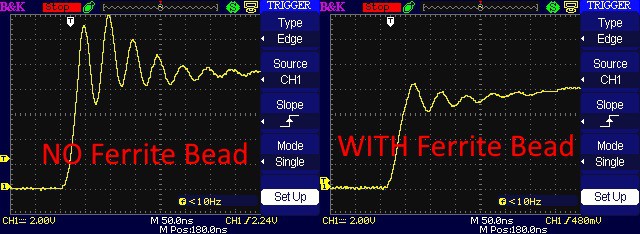
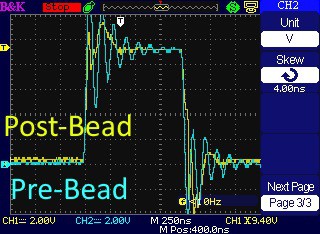
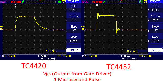
A normal camera flash is not fast enough to capture these images!  Below is a comparison of a typical camera flash vs this high-speed flash (1-μs duration).  Both air rifle pellets were fired from the same rifle, travelling about 280 m/s.  This demonstrates the advantage of using a high-speed flash for high-speed photography.

DIY High-Speed LED Flash
Nikon SB-900, Minimum Power
DIY High-Speed LED Flash
Egerton, 1 Microsecond

Anybody Can Do It

While typical camera flashes require a trigger system to fire, Edgerton is going to be equipped with a built-in tripwire trigger function.  All you need is a camera, a projectile, and a piece of wire!  The tripwire trigger works by placing a small wire strand in front of the projectile's path (usually in front of a rifle's barrel).  The user enters a delay into Edgerton, and it will flash exactly that long after the projectile has broken the tripwire!

Edgerton can also use the same trigger system as a typical camera flash.  This means it's compatible with DSLR's or wireless trigger systems.


Are There Alternatives?

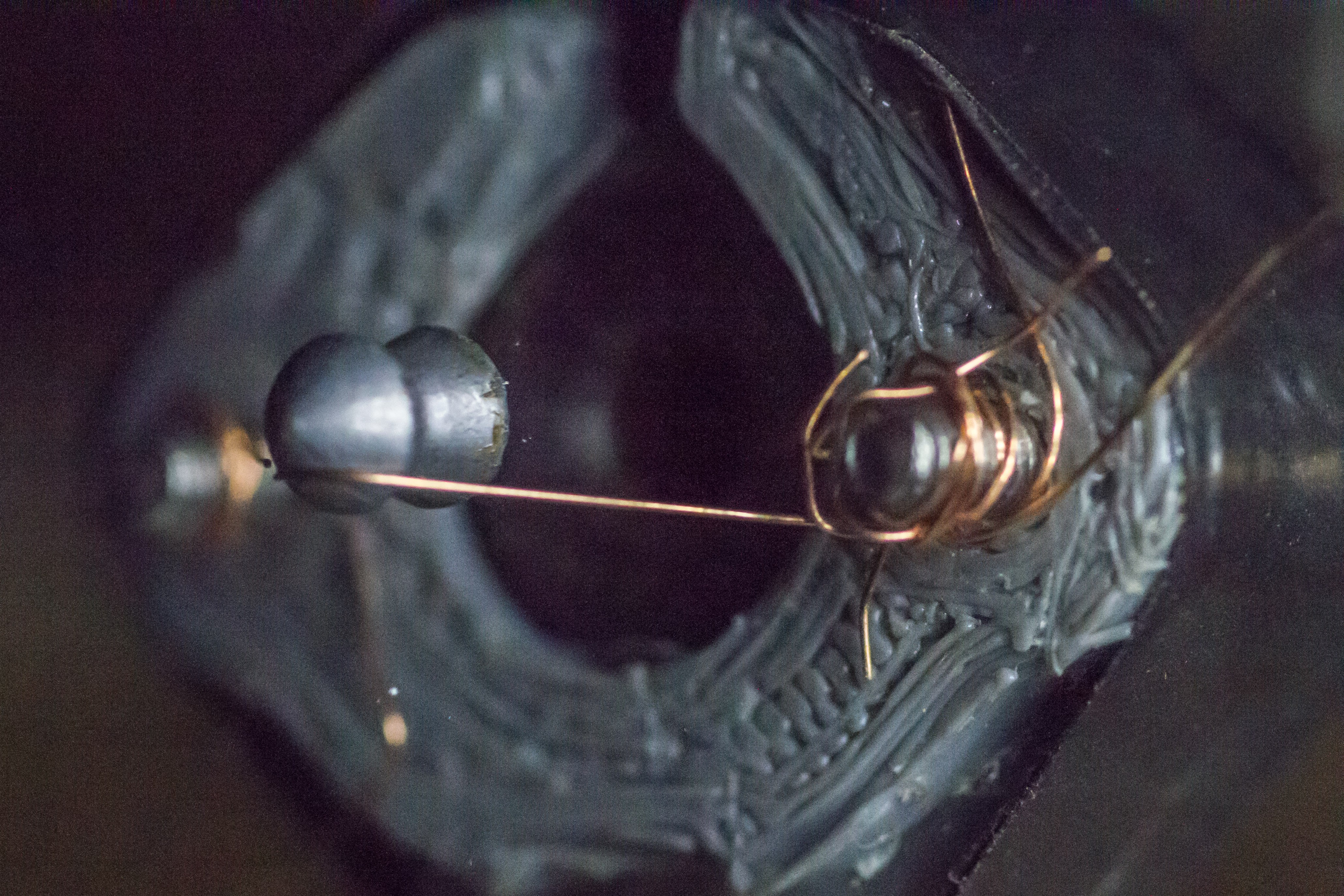
High-speed photography is no recent invention.  Doc Edgerton was already experimenting with high-speed photography in the 1940's, and has taken some incredible photos.  He was known to use an Air-Gap Flash, which is similar to the Xenon flash tubes found in modern camera equipment.  It unfortunately requires much higher voltage which could easily cause injury (SEVERE injury).  While I didn't completely disregard the option, I eventually opted for a safer solution.

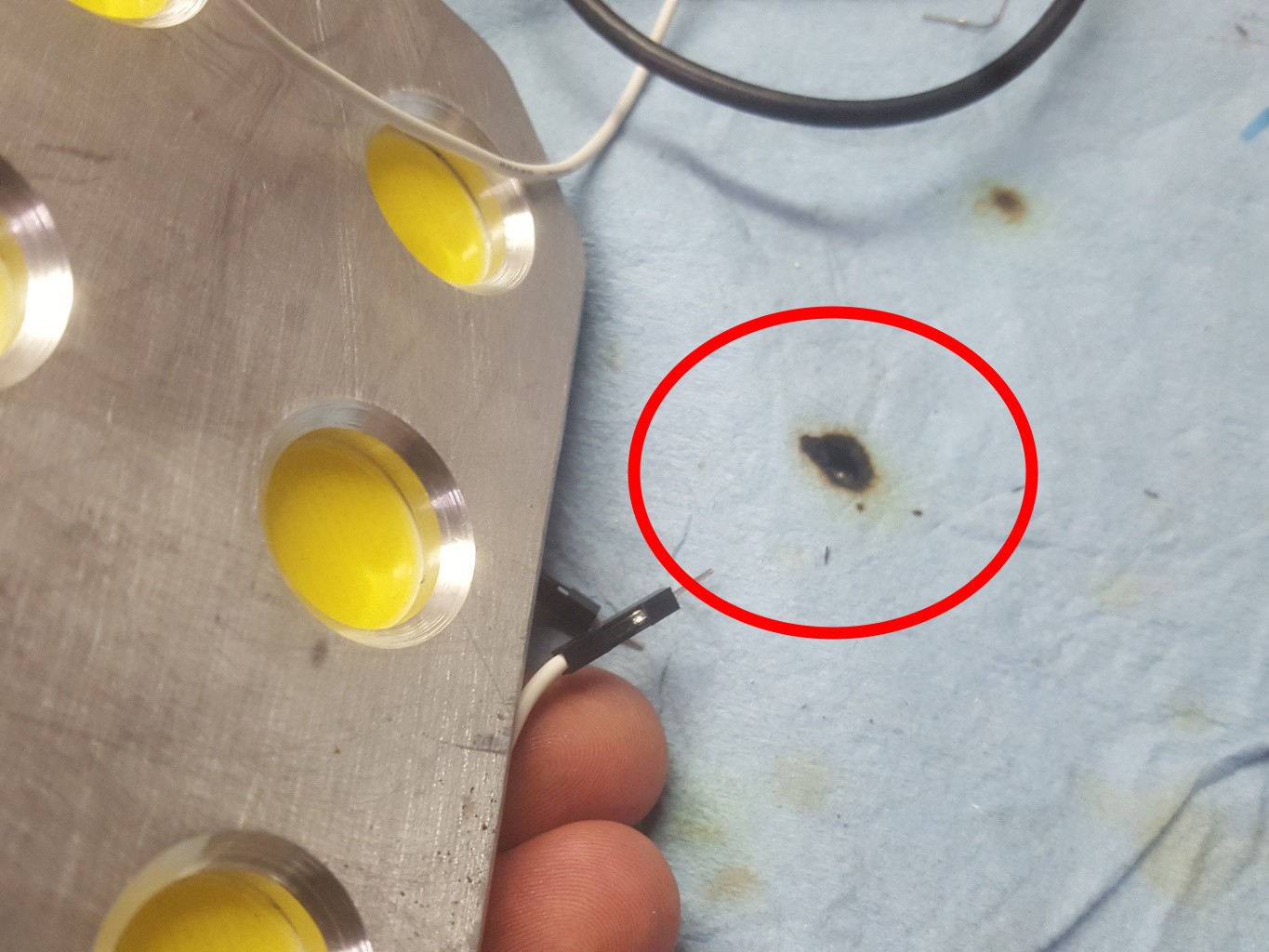
A recent kickstarter campaign (Vela One) offered a high-speed LED flash.  It can produce flashes lasting 0.5 μs (microseconds), was not dangerous, but was priced about $1,750 CAD!  A significant amount of development resources was put into this commercially-available flash.  I've likewise conducted destructive testing with expensive components and put much time into developing the Edgerton. 
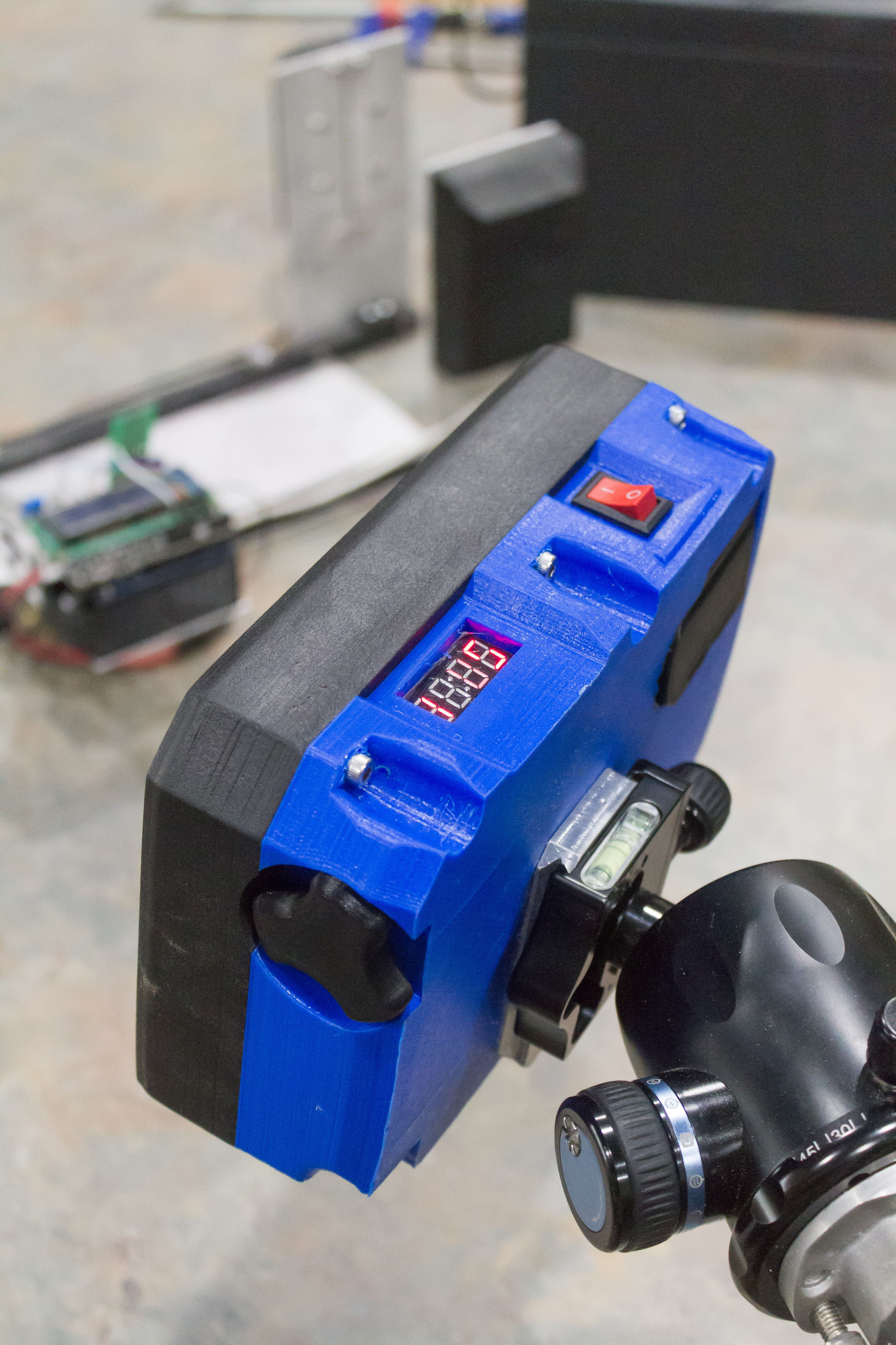

Feature Set

  • Simple user interface consists of an encoder, 4-digit LED display, and power switch
  • Tough plastic case for real-world use
  • 3.5mm Jack for multiple types of external triggering
  • Arca-Swiss mounting plate compatible with many tripods
  • 1/4" threated hole for non-Arca-Swiss tripods
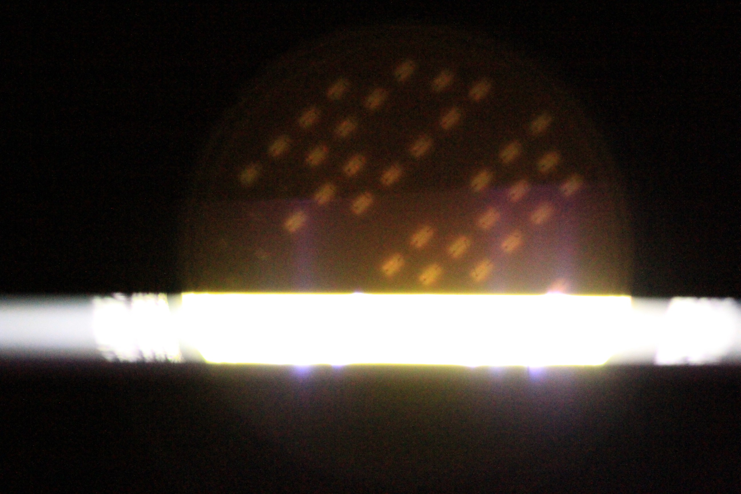
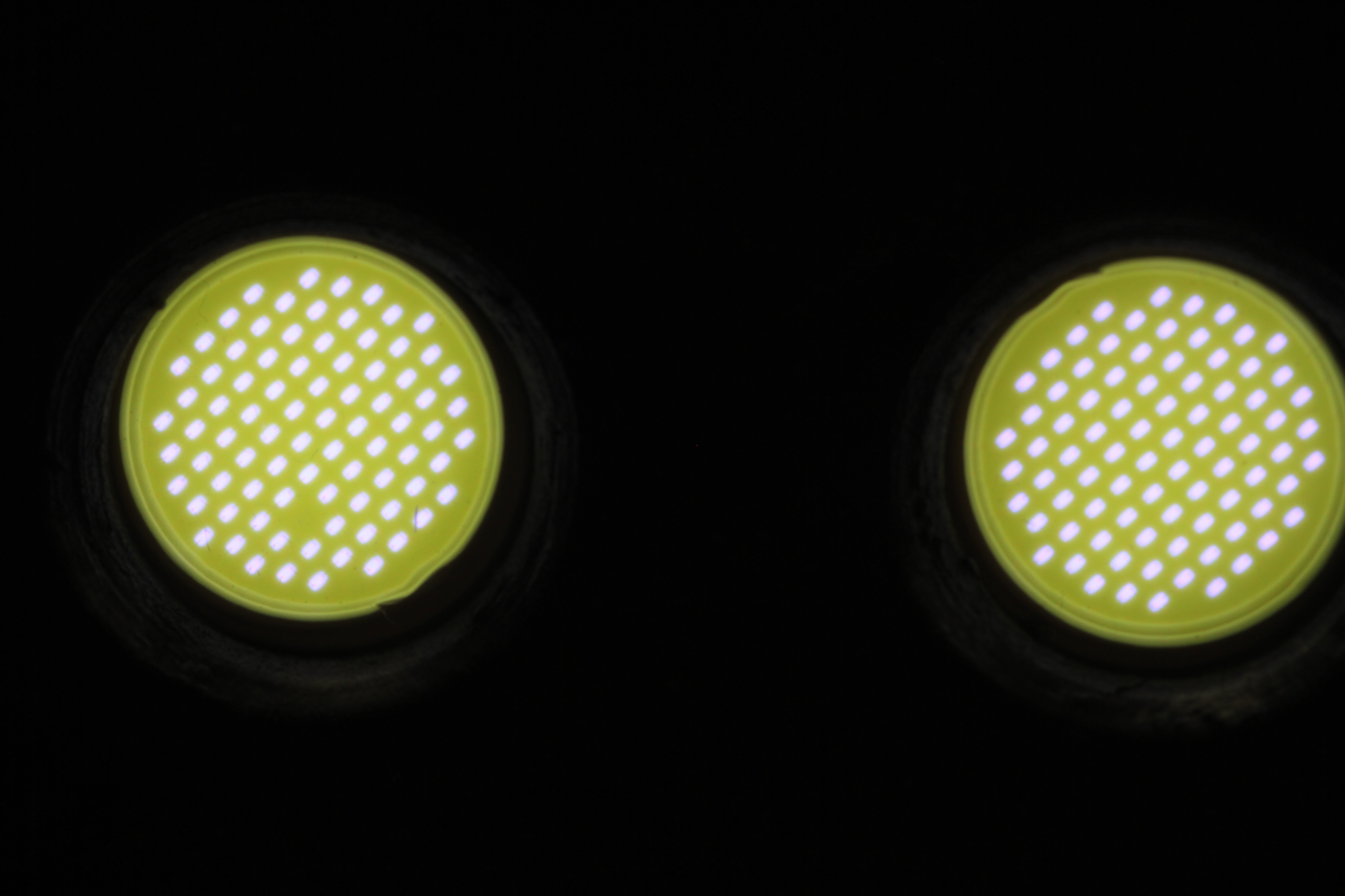
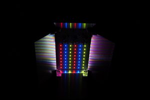
  • 12x high-powered Cree LED's are capable of well-exposed images in one microsecond
User Interface
DIY High-Speed LED Flash
High-Power Cree LED's


3rd Party Licenses

... Read more »

Assembly Manual 1.3.pdf

Complete guide for assembling Edgerton

Adobe Portable Document Format - 5.52 MB - 07/07/2020 at 04:33

Preview
Download

Edgerton Firmware 0.2.8.zip

Firmware for ATMega328P microcontroller

x-zip-compressed - 60.49 kB - 04/14/2020 at 03:00

Download

User Manual 0.2.8.pdf

User manual for Edgerton

Adobe Portable Document Format - 38.05 kB - 04/14/2020 at 02:59

Preview
Download

STL 1.2.zip

STL files for 3D-printed components

x-zip-compressed - 2.46 MB - 03/20/2020 at 19:23

Download

BOM 1.2c.csv

Bill Of Materials, everything required for assembly

- 10.10 kB - 03/20/2020 at 16:41

Download

View all 8 files

  • 12 × Cree CXA2530-0000-U20E3 LED’s White LED's with high output/cost ratio
  • 4 × Vishay MKP1848S 10μf Capacitors To supply the LED's
  • 1 × 45-390V Boost Regulator To supply the Capacitors - no model number, no datasheet, just search the description on eBay
  • 1 × ATMega328P Microcontroller The brains
  • 1 × LM7805 Linear Regulator To supply all the 5V components

View all 18 components

  • Mark 2 - Development Update

    Tyler Gerritsen12/29/2019 at 15:43 0 comments

    The new high-speed flash is my pet project, but unfortunately it hasn't been at the top of my priority list recently.  Work and family life have used up most of my time, leaving very little for the Mark 2.  There have been a few developments recently and I wanted to share!


    High-Power Lighting - WOW!

    I finally have a working offline driver for the LED's based on the DI AL9910 driver.  Three LED's can handle all of the power from a 144W power brick from Amazon, so sharing the load among all 12 LED's will result in a very long lifespan.

    Story time... I had three LED's powered up and was working on the unit.  So, I placed the LED's face-down on a shop towel.  Within two seconds I began to smell smoke... Turns out the shop towel was catching fire!  The LED's weren't even warm at this point, but the power output was enough to ignite paper!

    Read more »

  • Mark 2 - Development Update

    Tyler Gerritsen11/02/2019 at 02:08 0 comments

    Development is continuing!  Here are a few blurbs about recent design work.

    Control Board Design 95% Complete

    The main control board design has been generally completed.  A few minor tweaks need to be implemented (primarily related to the high-power DC converter, which hasn't been designed yet).  Some testing has been performed with the prototype board and the MIC2171 flyback converter I found on eBay


    Read more »

  • Control Board 1.2 Released

    Tyler Gerritsen09/29/2019 at 03:25 0 comments

    What's changed?

    1. Simplified External Trigger Protection - A single 1N4001 diode and two resistors protect the microcontroller from most causes of damage.  This protection circuit is cheaper and simpler than the V1.1 circuit, but much better than the V1.0 circuit.

    2. Solid-State Relay (SSR) Boost Control - Instead of the complex circuitry introduced in the V1.1 design, a single component is used to turn the high-voltage boost converter on and off.  The voltage drop on the load side is about 200 mV when driving the boost regulator, while it only uses less than 50 mA to run.  This is much better than earlier control circuits.  A number of SSR's will work, but I recommend the Vishay VO14642AT ($3.81 CAD on Digikey).
    3. Single Control Board - With the SSR mounted on the main control board, there is no need for a second control board for the boost converter.  This simplifies both construction and the wire routing inside the case.
    4. Pre-Built Control Boards Available For Purchase (SOON) - I've prototyped a control board and will have a small number manufactured soon for those who are interested in building a flash.  I hope to keep the price low with a slim profit margin to support my continuing experimentation with the LED's.

    What else is going on?

    Development of the Mark 2 is ongoing.  The control board has gone through several iterations, a handful of LED's have been destroyed with the powerful new circuitry, and I only wish that I had more time to devote to its development :)

    I'm also working on organizing an overview of my experiments for those who are interested in all the details.  The setup and results will be shared, likely on my website (www.td0g.ca).

    NQTRONIX has sent an active light probe which arrived a few weeks ago.  Sadly I haven't had time to experiment much with it, but hopefully soon I can begin collecting data to answer a number of questions.  I've built a crude integrating sphere to use with the probe.  Here's a teaser from the fooling around I've done so far:  The LED's appear to turn on REALLY REALLY fast and turn ALMOST off JUST AS FAST.  My claims of sub-microsecond pulsing will soon be proven with some oscilloscope traces!

  • Mark 2 - Development Update

    Tyler Gerritsen08/13/2019 at 03:34 0 comments

    It's been some time since I posted about the continuing development of the Mark 2.  Progress has slowed recently as I've been distracted by a back injury, meanwhile my work and family have taken some priority over the project.  Here's a summary of the Mark 2 progress thus far:


    Electronics

    The LED circuits have not changed at all.  The control board, however, has undergone a complete redesign.  One of the main goals was the ability to run on 4x AA batteries (3.2 - 6.0 Volts).  Realization requires three switching power converters (I purchased complete converter boards in order to save development time):

    • 3.3v converter for the control board (Pololu S7V8F3)
    • 15v converter for the gate driver (SX1308 Boost, purchased from eBay)
    • 125v capacitor charger (MIC2171 Flyback, purchased from eBay)
    Read more »

  • Tripwire Trigger System Functional

    Tyler Gerritsen07/01/2019 at 13:22 0 comments

    Various methods of triggering are available for high-speed photography, but the triggering systems are not cheap.  In an effort to make the hobby accessible and affordable, I've added a built-in triggering system that doesn't require any major hardware.  The 'Tripwire Triggering System' works by placing a special jig on the muzzle of the rifle.  A fine wire is positioned in front of the barrel, and when the projectile breaks the wire, Edgerton will strobe after a pre-programmed delay.

    Here's a photo with the triggering system set to 0 delay (triggering as soon as the tripwire is broken).  You can see the tripwire breaking just left of the projectile.

    Read more »

  • Edgerton V1.1 Released

    Tyler Gerritsen06/09/2019 at 15:14 0 comments

    What's New?

    The design for Edgerton has been updated to address several issues in the original design.  The circuit diagram, bill of materials, and 3D print files have been updated.  A new complete assembly manual has been written and made available.  The overall cost has increases slightly (less than $5) because of some new components.  Assembly requires a few more steps, but they are simple and the benefits greatly outweigh the cost and added assembly time.  Below is a brief overview of the changes and their rationale.


    Reduced Power Consumption

    The microcontroller's isolation from the high-voltage boost converter is important to prevent resetting, and this was originally accomplished using a relay board purchased from eBay.  Unfortunately the relay drew several hundred milliamps, about as much as the boost regulator.  

    The relay has been replaced with a P-channel MOSFET, opto-isolator, and a couple resistors.  The new circuit draws about 30 mA - and may be reduced further with some optimization.  Isolation is maintained via the opto-isolator.  The cost has not increased and the circuit is easy to assembly and install.  A small benefit is the removal of the relay mount in the case, which means a reduction in filament usage.


    Ferrite Beads for the Gates

    I previously noticed some significant ringing in the MOSFET gates.  Thanks to advice from a friendly German named Volker and guidelines presented in this application note from ON Semiconductor, I ordered some ferrite beads and installed them at the MOSFET gate leads.  Here's the gate signals before and after the ferrite beads were installed.

    The gate signal is cleaner.  Here's a trace showing how much the ferrite bead cleans up the signal.

    Read more »

  • Major LED Failure!

    Tyler Gerritsen06/03/2019 at 03:41 0 comments

    The Incident

    After days of torture-testing a single LED before it even started to show evidence of damage, I managed to fry all twelve LED's in a single unintentional event.  That's $80 bucks of electronics GONE! 

    I felt like Mark Watney from The Martian (the scene that happened in the novel but was sadly missing from the film...  If you read the book, you know the part).  To quote XKCD:

     I have never seen a work of fiction so perfectly capture the out-of-nowhere shock of discovering that you've just bricked something important because you didn't pay enough attention to a loose wire.

    The event happened while I was experimenting with a switching regulator.  I hoped to decrease the number of AA batteries required, so I grabbed a boost regulator from eBay and set it to 12 volts.  Then powering the boost regulator from a 5V power supply, I started testing current draw during operation.  So the LED's functioned before these tests, but didn't work afterwards.

    Read more »

  • Phosphor LED Turn-Off Time​

    Tyler Gerritsen06/01/2019 at 20:14 1 comment

    The Potential Problem

    I've received a few comments regarding the type of LED that Edgerton uses.  Specifically, the LED's may not turn off fast enough.  This is a problem I didn't really consider previously, given a statement in the Cree application note (pp. 10: The typical turn‑on time for an device is on the order of 10 nanoseconds or less).  Since they turn on in 10 ns, why can't they turn off as fast?

    Well, it turns out that the LED's use a little trick to make white light.  The actual LED modules make a blue light, and a layer of phosphor in front of the LED's turn the blue light into a spectrum of light ('white light').  While the LED's can turn on and off quickly, the phosphor is delayed in turning off (and maybe on - I don't know yet).  Notably, Edgerton's primary competition (Vela One) appears to use a similar type of LED and the manufacturer defends their flash durations on their website.

    Experimental Proof Of A Minor Problem

    Here's an experiment that demonstrates the problem.  It's a photograph of the LED flashing a 1-microsecond pulse.  There are three stages of the flashing cycle observed here:  The bright strip of light is the 1-microsecond flash, the illuminated dots above are the LED modules AFTER the flash, and the darker area below are the LED modules BEFORE the flash.

    There were MANY failed attempts to take this photo.  Ignore the absent LED modules, this was a damaged chip.

    Before explaining how this image works, I'll explain what it tells me.  The LED's above the flash strip show that there is some lag in turning off.  But during the turn-off time, the phosphor doesn't output much light.  In other words, the LED is incredibly bright for one microsecond, but then becomes dimly lit for some time afterward.

    Read more »

  • 150,000 Flashes Later

    Tyler Gerritsen05/29/2019 at 02:25 0 comments

    Strobing the LED's at several times their rated voltage is one thing, but a good flash needs to have a useful lifespan.  I began testing the lifespan of the unit a couple weeks ago.  Testing was done using only one LED (too expensive to risk multiple LED's) strobing at 1 hZ.  I started at 70 V, cycling 10,000 times at 1 microseconds and 5,000 times at 4 microseconds.  The LED was aimed at an 18% grey card 20 cm away and a DSLR photographed the card every 20th flash.  After the LED cycled 15,000 times I incremented the voltage +5 V and started again.  At 95 V, the LED showed no sign of quitting so I increased the flash rate to 2 hZ and photographed every 50th flash.

    Well, it turns out that the LED could handle all the way up to 125 V - and I stopped the test as the circuit board wasn't designed for more than that!  The photos were batch analyzed with ImageJ and no fluctuations in light output was observed.  Above is a photo of the LED with 150,000 flash cycles vs an LED that didn't go through the torture test (0.3 seconds vs >0.001 seconds total illumination time).  Interestingly a single element died at some point, but it still conducted current and light output was barely affected.

    Read more »

  • Voltage-Exposure Testing

    Tyler Gerritsen05/25/2019 at 19:33 0 comments

    Shortly after assembling the device, I tested a bank (3x LED's) by increasing the voltage until the LED's were damaged.  The test began at 45 V and incremented by 10 V following a single flash.  Major damage occurred at 125 V.

    More recently, I started a series of longevity tests with a single LED.  It was strobed over 100,000 times at various voltages.  Surprisingly, the LED reached 125 V and survived a battery of cycles at that voltage.

    Some head-scratching later and I realized that the FET driver was changed since the original destructive testing (TC4420 to TC4452).  The new driver could ground the MOSFET gates faster, shortening the pulse and probably preventing the LED from premature death.

    Read more »

View all 11 project logs

  • 1
    Source All Required Components

    Download the Bill Of Materials from the github repository at https://github.com/td0g/high_speed_flash/blob/master/BOM%201.1.csv

    Purchase all the hardware listed.  Components purchased from eBay / Alibaba / Bangood require several weeks shipping time.  You may want to get started on assembly before all components have arrived.

  • 2
    Prepare the Tools

    Be sure to have the following tools ready:

    • 3D printer with 200mm x 200mm bed
    • Soldering iron & solder
    • Small side cutters
    • Hot glue gun
    • Allen wrenches
    • Dupont crimper kit (optional but recommended)
  • 3
    Follow the Steps in the Edgerton Assembly Manual

    Download the Edgerton Assembly Manual from the Github repository at https://github.com/td0g/high_speed_flash/blob/master/Assembly%20Manual%201.1.pdf

    Follow all the steps outlined in the manual.

View all 3 instructions

Enjoy this project?

Share

Discussions

erniehatt wrote 09/05/2020 at 23:22 point

Is this project still on going.

  Are you sure? yes | no

Tyler Gerritsen wrote 09/10/2020 at 17:07 point

Hey Ernie!  Sorry for the delay - time is in short supply. 

The 'Mark 1' Edgerton has reached maturity and I'm not doing any more development on it.  The 'Mark 2' E2 is being developed and I'm working on finalizing the assembly instructions right now.  More info about the E2 is available at https://td0g.ca/2020/06/29/e2-a-the-high-speed-led-strobe-mk-2/

Both models are very similar, you can read about the differences at https://github.com/td0g/high_speed_flash

  Are you sure? yes | no

erniehatt wrote 02/21/2020 at 06:57 point

What a great project, I have built 4 Airgap flashes in the past, but as age has court up with me , they rather scare me some now..

I would love to make a circuit board for this, rather than use a perf, is this a god idea. What would be the dimensions needed.

Thanks for puting the effort.  Ernie.

  Are you sure? yes | no

Adlerauge wrote 02/12/2020 at 22:15 point

Dear Tyler,

could the edgerton be used in strobe mode
right now? E.g. at 2 kHz, for 10 ms; means
20 flashes. Camera in long-exposure mode.

To visualize a bullet or ball flight.

Firmware has to be adapted I think (as now only
flash duration and trigger delay can be set),
but has the hardware to be adapted also?

I would prefer to use IR (LEDs).
Any recommendations for this?

Best regards
Jan

  Are you sure? yes | no

krzysztof krzeslak wrote 07/27/2019 at 22:08 point

Aaaweomse :).

do you plan to make some units assembled, or at least some kits for assembling ? if yes put, me on top of order list ;)

i see thatit's something which can help with my project, but I wondering did your flash got input for external triggering ? 

Also i'm wondering about that is it possible to use this unit as a continuous light source ? I'm asking because i found out that for some shoots high shutter speeds are enough to freeze motion, but in such case to make nice photo you need powerful light source, so if this unit will serve as both it will be something that I think is not currently available on market(at least i did not saw something like this) ;)

  Are you sure? yes | no

Tyler Gerritsen wrote 07/29/2019 at 12:38 point

Thanks Kermit!

I was just admiring your camera controller this morning and was surprised to find out you had commented on my flash!  I'm quite interested in the controller and must say that it looks like a professional product.  Kudos!

I'm thinking of selling the 'Mark 2', either constructed or just a kit...  We will see after I'm finished the design!  I'll keep you in mind!

Yes, Edgerton has a 3.5mm port with two functions.  For people who don't have a flash controller (such as yours), you can build a 'tripwire trigger' very easily and setup a flash delay.  It can also be used with an external trigger (I have a home-built ballistic chronograph) and flashes immediately when a signal is received.

Continuous lighting would be a great idea, but there are two major roadblocks right now.  First the LED's don't have any type of heatsink so they will have to be run at LOW POWER to avoid overheating.  Second, the voltage converter is VERY under-powered for continuous lighting.  Maybe in the future I can try modify the design for continuous lighting :)

  Are you sure? yes | no

krzysztof krzeslak wrote 07/29/2019 at 21:23 point

hehh thanks, on other hand i'm also get a deeper view into your project, great documentation and final effect it's great to hear that you did't forgot putting standard 3,5mm jack trigger, it means that it should flawlessly operate with my controller and currently i'm quite fascinated about idea of trying it out ;)

What comes to my mind is maybe you got some free units/prototypes of your flash lying around and you are willing to make exchange for my controller ;) ? It would be great as i as i got some working prototypes lying around which i'm willing to exchange ;)

  Are you sure? yes | no

Tyler Gerritsen wrote 07/29/2019 at 22:11 point

I would trade a flash for a controller! Right now I don't have any extras though. The Mark 2 is being developed and won't be finished for some time. When it is, I will contact you and we can make a deal :)

  Are you sure? yes | no

krzysztof krzeslak wrote 07/30/2019 at 07:28 point

great, i'm looking forward for it ;)

  Are you sure? yes | no

Tyler Gerritsen wrote 07/29/2019 at 22:14 point

By the way, I'm thinking about making the continuous light source function but I don't have any experience with constant light. Only flashes! I googled Video Light Kit and the first result was a 10W LED on Amazon. Is that enough light for most applications? Or how much would be 'good enough'?

  Are you sure? yes | no

krzysztof krzeslak wrote 07/30/2019 at 07:44 point

Hmm unfortunately 10W led seem a bit to low, currently i'm using constant lights source which is made of 8 CFL bulbs(2 unit, with 4 bulbs each), each has power of 85W and manufacturer states that each should give 4900lm, so they should provide almost 40 000lm.

....aaand this was enough to took photos at 1/4000`s shutter speed, but stil i had to use quite high iso, so even higher values can be very handy, but this are pretty high values so i'm not sure if this idea is something that can be done, but if this will be possible it would be great as your flashes can give some great advantage regarding this CFL lights, when you will look at movie which i provided for my project you will see some "flickering" this is caused by this CFL light and using led as lights source i think it could be avoided, so this will be usable also for high frame rate filming ;)

  Are you sure? yes | no

Tyler Gerritsen wrote 07/30/2019 at 14:16 point

Thanks for giving me an idea where to start.  40 000lm is LOTS for the little batteries to supply and there will be much heat to dissipate.  There will definitely not be any flickering in a video since the LED's can strobe at up to 200 kilohertz (unless your recording more than 100 000 fps!).

I'll look into this as several people have asked about continuous light mode.  Maybe use an external power supply (2.1mm power jack) for high-power lighting and AA or 18650 batteries for strobing and low-power lighting.

  Are you sure? yes | no

krzysztof krzeslak wrote 07/30/2019 at 15:14 point

Yes i think adding an external supply connection is a great idea as yeah definitely using battery will cause a lot of problem at such power rate, but external power source for constant light source should't be problem, as they are being used commonly in places where you can access power outlet I mean in some studio`s etc.

Also for creating high fps movies purposes what comes to my mind is that, even something like "semi-constant light" i mean that even about 3 seconds of high power illumination will be enough for high speed filming purposes,i thought about it as for example camera which I'm using for this is able to catch up to about 3second for 250fps(even less for higher frame rates). So maybe doing something like this, can be helpful to avoid overheating, but it's just quick thought

I checked what are typical lumen/watt rate for high power leds and from quick research it seem to be somewhere around 100lm/1w, so it's around 2x better than CFL lights which I currently use, so it's also sounds good ;)

  Are you sure? yes | no

Tyler Gerritsen wrote 07/31/2019 at 14:58 point

This morning I did a quick test.  I put one LED about 30cm away from an ammeter and voltmeter, and a camera about 50cm away from the meters.  The camera was set to f/8.0 and ISO 800, the shutter speed was automatic to get the proper exposure.

At 1W the shutter speed was 1/20s, 3W was 1/50s, 8W was 1/100s, 15W was 1/200s, and 23W was 1/250s.  I don't know how many lumens that is, but it gives an idea.

If I turned ISO to 6400 and aperture down to f/4.0, then it can do 1/4000s shutter at 23W.  They could definitely go higher than 23W each (but loosing efficiency), and there are 12 LED's in the flash...  It should work!  Thanks for all the input!

  Are you sure? yes | no

krzysztof krzeslak wrote 07/31/2019 at 18:26 point

Great! This definitelly sounds good i just check datasheet for those leds you are using and there's written that each can give between 3680lm(at 85deg)-4150lm(at 25deg), so it mean that if there are 12 such leds in single unit it should give about 44000lm(at 85deg) ! :D it sounds good as potentially at full power this will produce as much light as 2 commercial units which i'm currently using ;), so even with half of power of your flashes(or lamps;)) should give some decent ilumination.

  Are you sure? yes | no

Tom Nardi wrote 06/05/2019 at 06:14 point

Such an awesome project, glad to see you decided to enter it into the Hackaday Prize this year.

Very interested in seeing the Mark II, and the design changes made in regards to getting ready for larger scale production. I really like your approach there, having a "Classic" version that people can assemble on their own, and then evolve that into a commercial addition intended for the everyday user.

  Are you sure? yes | no

Tyler Gerritsen wrote 06/05/2019 at 14:11 point

Thanks Tom, I appreciate the encouragement!  I really don't have experience with DFM, so starting with a working design seems like a good way to get going.  I'm not even sure if it will even enter production since the market is so small.  Cheers!

  Are you sure? yes | no

Alan Green wrote 05/25/2019 at 21:41 point

Thank you for the very complete write up. I learned a lot from the testing and fault finding. The  MOSFET driver's sub-microsecond asymmetry between on and off times must have been fun for you to find.

  Are you sure? yes | no

Tyler Gerritsen wrote 06/04/2019 at 22:52 point

Thank you Alan!  Yes, I have a fairly rudimentary understanding how MOSFETs behave, and using an oscilloscope on them is always a learning experience.  I've recently applied some newly learned techniques to controlling the gate ringing (ferrite beads and different resistors), the signal has improved quite a bit!  Cheers, Tyler

  Are you sure? yes | no

Michael G wrote 05/25/2019 at 06:30 point

Might be worth considering adding an adjustment to change the brightness with a potentiometer or something similar (just an idea -- not my area of expertise by any means). Very cool project!

  Are you sure? yes | no

Tyler Gerritsen wrote 05/25/2019 at 13:45 point

Thanks for your interest and the like Michael!  The potentiometer idea intuitively makes sense, but for a high-speed flash it's actually counter-productive.  That's because the user ALWAYS wants the flash to be as short as possible, so Edgerton keeps the LED's at max power and just changes the amount of time they're on (too much light? turn down to 1/2 microsecond).  Cheers!

  Are you sure? yes | no

wim wrote 05/22/2019 at 09:36 point

Hi Tyler,

What an inspiring project this is! I was thinking along these lines a couple of months ago (triggered by the velo one indeed), but deemed it's design beyond my electronics skills. With this documentation I think I will give it a try, after the summer. A few questions:

- have you tried to approximate its guide number to get us an idea of the output power?

- would it be easy to change the design to six leds instead of 12 (for use in close-up photography)?

- can the leds also run continuously at low power, to serve as modeling lights?

thanks & good luck,

Wim

  Are you sure? yes | no

Tyler Gerritsen wrote 05/22/2019 at 14:02 point

Thanks for liking and following Wim!  Those are good questions, I'll answer best I can.

-Not yet, I will test that and update when the current endurance tests are complete.  The LED's have a wide viewing angle (110 degrees) so it will have a very low GN compared to its actual energy output.  Lenses or reflectors would improve the GN and I'm looking into adding those.

-Very easy!  The case needs to be redesigned, but no other major modifications needed.

-That's a very good idea, a couple complications that need to be addressed first.  Currently the LED's don't have heatsinks, so they will overheat quickly if run continuously.  Also it would need an adjustable boost converter to switch between high-voltage and low-voltage.

I'm going to keep the modeling light idea in mind :)  Cheers!

Tyler

  Are you sure? yes | no

Similar Projects

Does this project spark your interest?

Become a member to follow this project and never miss any updates