 Yann Guidon / YGDES
Some of my more detailed logs have been turned into actual projects:
- #Yet Another Electronic Lampyridae
- #FlappyScope
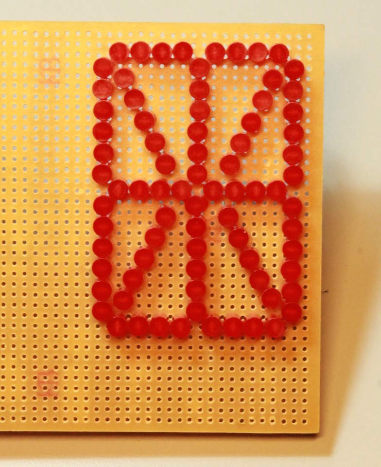
- #dual-mode 16-segments LED display module
- #Simon Says learn Pi and IoT
.
Logs:
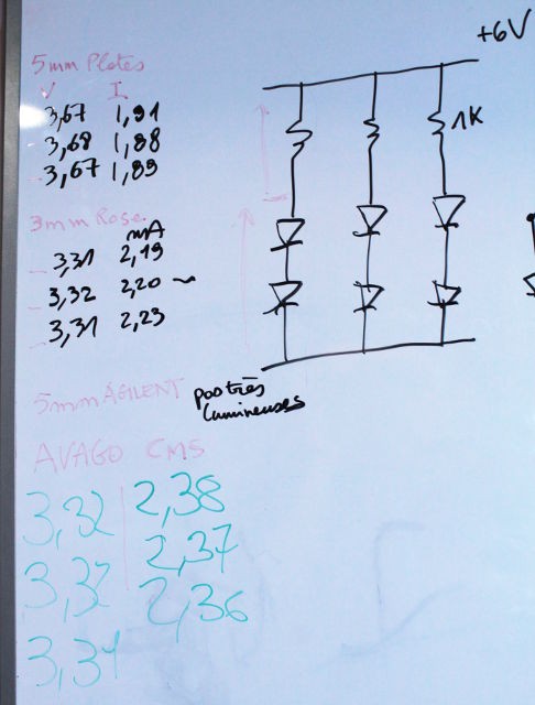
1. Diodes, charge pumps and MOSFETs
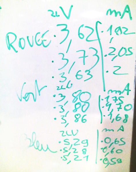
2. More diodes, charge pumps and MOSFETs
3. The dawn of a new project
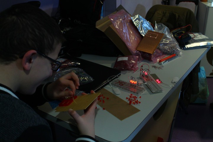
4. Getting our hands dirty at last
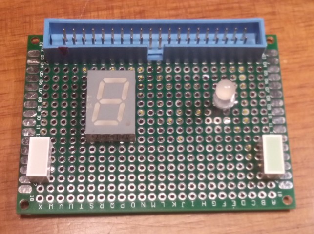
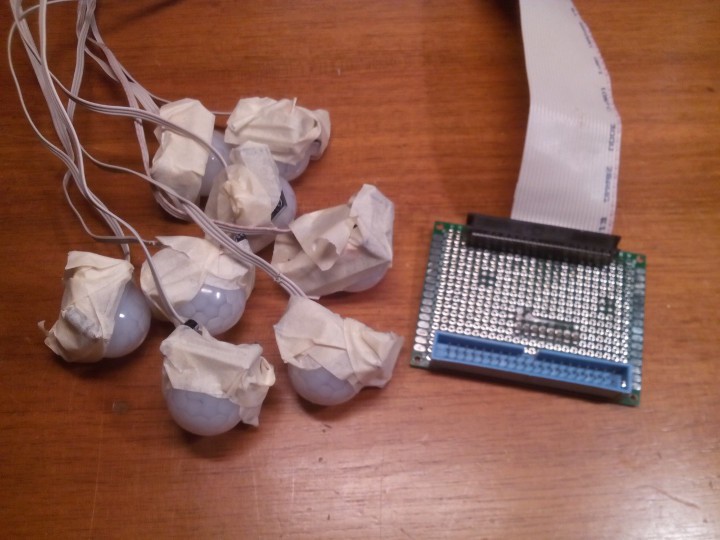
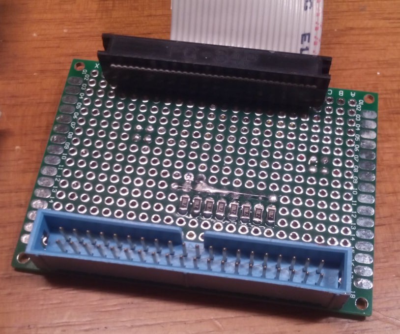
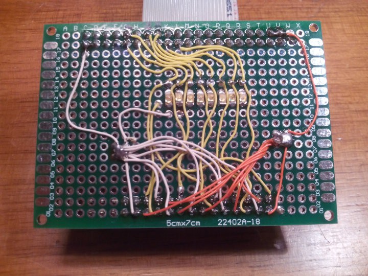
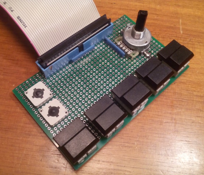
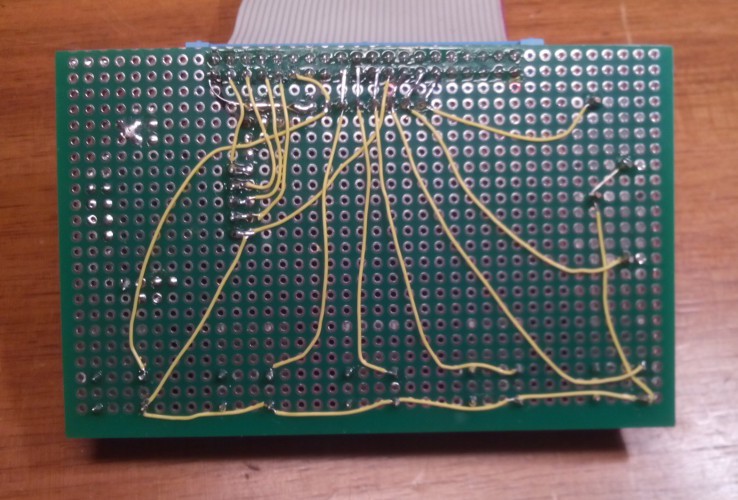
5. Raspberry Pi educational boards
6. Another fork
.
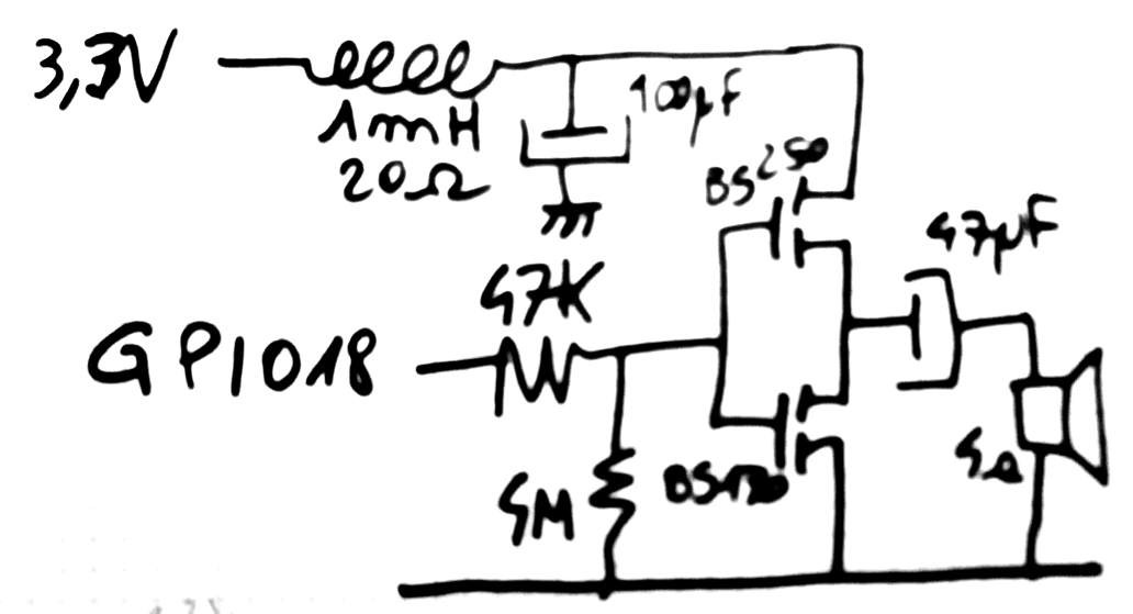
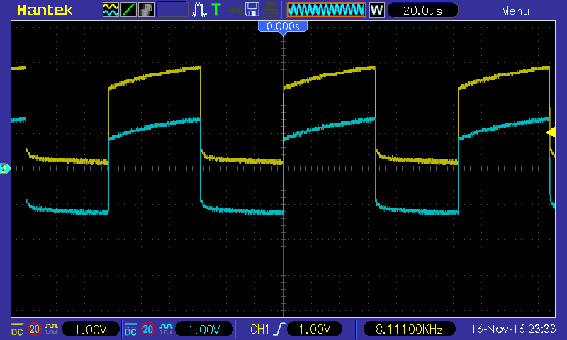
 The trace has shifted upwards, the capacitor's electrode is at a higher mean voltage than the power supply.
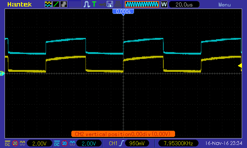
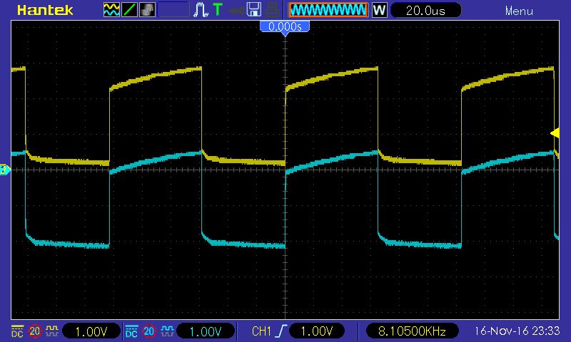

 Tyler Gerritsen

 Christoph Tack
 Tim
Tim