Close
0%
0%

Eyetooth Gaming Keypad

This is a 37 key gaming keypad set up for the common fps/rpg keys with key redefinition.

Similar projects worth following
It is a diy keypad inspired by the Ideazon Fang Gamepad. It uses cherry MX style switches and features reprogrammable keys and optional autorepeat.


For the most part eyetooth simply works as a standard keyboard with n-key rollover and no ghosting.

My goal was to cheaply replace my Fang keypad, ideally with something that has the key layout I'm accustomed to.  I also wanted to take the opportunity to make some improvements. I eliminated keys I never used, went to mechanical keys,  and moved the Q.load key to where it was less likely to pressed accidentally.   It ended up almost exactly the same size as the Ideazon Fang except it is as thick as my standard keyboard.

In addition, it has two special features, auto repeat and key redefinition. 

I added auto-repeat because I physically cannot repeatedly press a key fast enough to satisfy some single-player games.  I don't play multiplayer games, so I don't know if that is useful there.  If so, don't cheat!

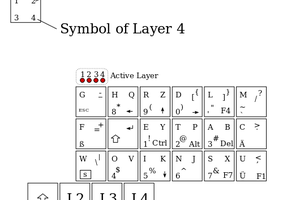
Finally, I added the ability to reprogram any key directly from the keypad.  I did this because I could and it would allow anybody who might build this to set up the keys as they desire without needing to reprogram the arduino.

In the future I might had support for multiple key-maps and/or macro support; but at present I don't have any use for those features.

BTW:  In the hacking spirit, I found the best anti-skid feet ever.  Assured heel grippers from the dollar store.  They are a grippy rubber, stick like crazy , and are only 2.6 mm thick.

Portable Network Graphics (PNG) - 49.18 kB - 09/17/2019 at 20:06

Preview
Download

keypad.ods

Spreadsheet documenting switch wiring.

application/vnd.oasis.opendocument.spreadsheet - 24.78 kB - 09/17/2019 at 20:02

Download

  • 1 × arduino pro micro
  • 37 × cherry MX style switches
  • 1 × Double sided foam tape to mount micro
  • 1 × keycap 23mm wide
  • 36 × keycaps 18mm wide

View all 11 components

  • 1
    Mechanical

    The switches should be inserted from the top and should snap in.  Trying to remove a keycap will probably cause the switch the pull out so it might be advisable to secure them with hot glue or similar. 

    The base has a mount for a tactile switch to be used as a reset.  It is not necessary and is untested since I'm still waiting to be resupplied.

    The top is designed for cheap ebay 3mm threaded inserts, but there is an optional top for using the bare screws.

    The micro usb cable feeds through the base piece and  is secured with a cable tie threaded through the provided lug.  The hole is dimensioned for an ankler micro usb cable but most of the cables I have on hand  will fit.

    I used the cheapest keycaps I could find on ebay.

    I used gateron clear keys, which seems to be an unusual preference for a key pad.  Use whichever style of key you prefer.

  • 2
    Wiring

    The switches are wired up in the usual way for a diode matrix keyboard.  I mainly used bus wire for convenience. Where the bare wires crossed over I used coffee stirrers in lieu of spaghetti tubing.

    WireGuide.png indicates how the switches are connected in the default configuration. keypad.ods is a spreadsheet representation of the keyboard matrix.

    When actually wiring, all keys on a column are directly connected. Each key on a row is connected to the bus for that row through a diode. The diodes are wired with the cathodes in common and the anode connected to the switch.

    The led is connected to arduino pin DIO 2 though a current-limiting resistor.  I used  390 ohm. 

    I used a connector for the side keys in the bottom piece to make development and testing easier.

    When wiring, make sure not to block the intersections where the bracing in the base reenforces the top.

  • 3
    3D printing

    STL files are available on github or  thingiverse.

    The CAD design is available on Onshape.

    The parts should be printed without supports.  The side key openings have support designed in which can easily be removed after printing.  The counter sunk holes have a thin layer to avoid printing a small opening in mid air.  That layer can be opened up with a drill or simply pushed through.

    Test pieces for 18mm and 23mm keycaps are available. These are provided to allow you to calibrate your print for a good fit for the switches and check clearance for your keycaps without wasting too much filament.

    There are two bases provided. The standard base is for 37 keys and has two side keys on the left (or if you're right handed mirror the part in your slicer) . The optional base for 39 keys has keys on both sides.

    There are also two top pieces. One uses 3mm inserts. The optional top just threads the screws directly into the plastic.

    I thickened the top by 3mm compared to that shown in the photos to give the keycaps a bit more recessed look.

View all 5 instructions

Enjoy this project?

Share

Discussions

John Silvia wrote 09/18/2019 at 16:22 point

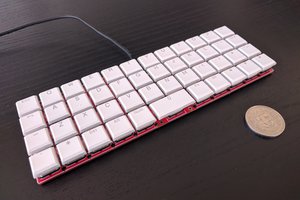
Thanks!  About the feet,  the funny thing is their curvature matches that of my keypad; but for more standard feet you can cut them into squares with scissors.

  Are you sure? yes | no

Dan Maloney wrote 09/18/2019 at 15:33 point

Good tip on the anti-skid feet, I'll have to keep that in mind. And I really like the way there's no offset between rows like there is on regular keyboards. I often find myself pressing E rather than W because of that offset.

  Are you sure? yes | no

Similar Projects

Does this project spark your interest?

Become a member to follow this project and never miss any updates