 Ben Brooks
My first (recent) microcontroller project turned me onto Particle Photons and got me looking for projects that would specifically benefit from having Wi-Fi functionality. Having recently gotten both security cameras and ‘smart’ lights, being able to have the doorbell trigger them seemed like a logical progression. As mentioned in the description, I didn’t want to alter my existing doorbell setup: partly for aesthetics/functionality but also as an added challenge. The first and primary hurdle was figuring out how to read the (relatively) high voltage AC that powers my doorbells.
A quick primer on wired doorbells: in the U.S., 12V AC is pretty common for powering them. (While I know in my case the transformer is rated for 12V, for whatever reason the voltage that each of my doorbells sees is actually 20V.) A quick google search will show you some diagrams for how things are typically wired. At each doorbell there are 2 wires (20V difference in my case). When the wires are shorted, the doorbell is activated. What this means, is that I needed a way to tell when the voltage difference between the 2 wires at each doorbell went to 0.
After doing a fair bit of googling to see how other people approached reading the state of a wired doorbell, I was surprised to find very little. I did however stumble upon a forum where someone was attempting to do this (or something similar) and optocouplers were recommended. The forum never resolved whether this worked for the original user but I decided to try it myself. (Optocopulers allow for signal isolation and simply consist of one side driving an LED and another side with a photoresistor reading the state of the LED.) While you can buy pre-made ones for quite cheap, I initially opted for making my own. I should also mention the fact that this would ideally be done with a DC power source on the LED side as AC voltage is constantly pushing and pulling or going high/low, so when directly powering an LED it will flicker (since they only allow current flow in one direction). In the US, this will be at a rate of 60 times a second. Not terribly noticeable to the human eye, but happening nonetheless. At the time I honestly didn’t know if it would meaningfully affect my use.
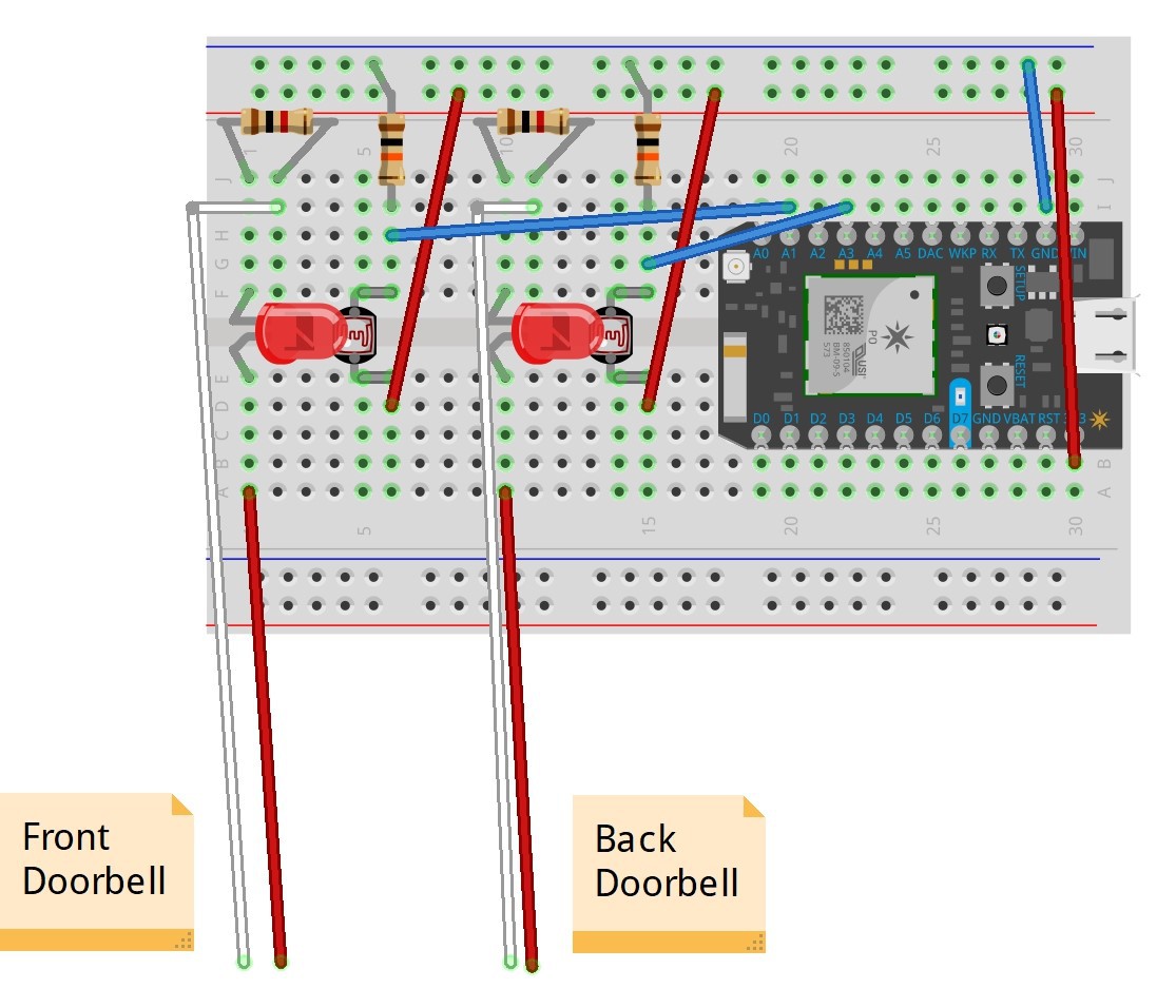
To test this, I simply took an LED and photoresistor from my parts bin and faced them towards each other, held in place and covered by black electrical tape (being careful to avoid shorting any of the wires). Wiring each up as you normally would (with the LED being driven by the doorbell wiring and the photoresistor being driven by the microcontroller), I was able to read the voltage on the photoresistor side with a multimeter and compare the pressed and un-pressed states. Somewhat to my surprise, my homemade octocoupler worked quite well: I was able to see very clear differences between the two states. Subsequently, I wired in the microcontroller and arranged things so that I got a ‘high’ state when the doorbell was un-pressed and a ‘low’ state when it was pressed. While there was definite variation due to the AC voltage, my photoresistor seemed to lag enough that it stayed pretty constant.
Fast-forward a little further and I was able to wire things up inside the house, connected to the wiring for both doorbells. I put it in a project box (but left it all on a breadboard) and put together some simple code to send Particle Publish commands when either doorbell was rung.
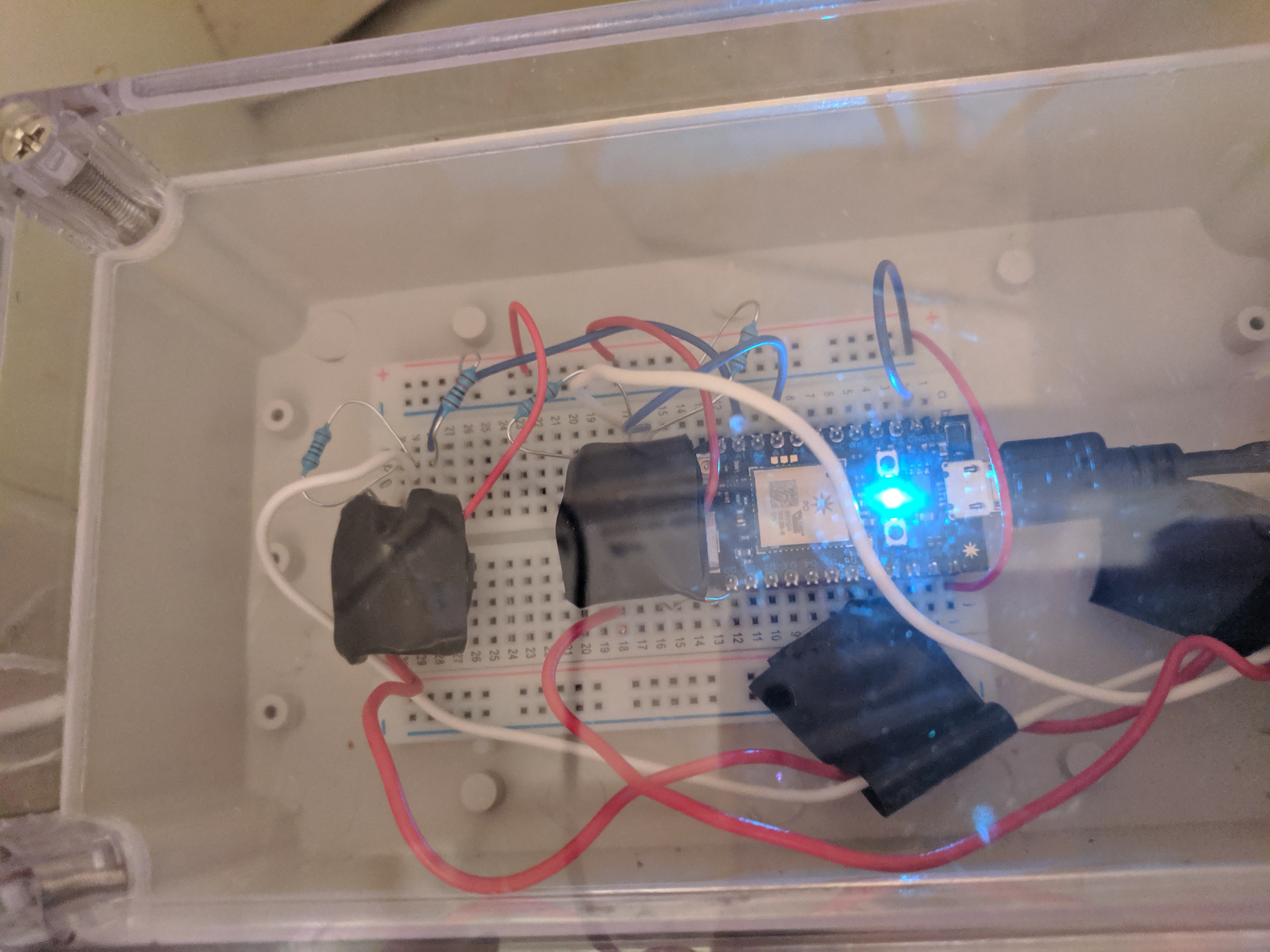
I actually left it this way for quite some time (read: over a year), both to fully test it out but mainly because it was working as-intended. Recently I started playing around with Eagle and designing my own boards; this seemed like a perfect project due to its small size and simplicity (it’d be awfully hard for me to mess up). However, before making a board I definitely wanted to use an actual optocoupler instead of my homemade ones. I found some quite inexpensive ones that fit the bill, ordered them and then proceeded with testing them as I figured they would act a little...
Read more »

 Alan Green
 Jakob Kilian
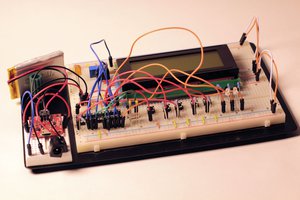
 The Feature Creep
Hello sir , where can i get the file for pcb?