 danjovic
BACKGROUND
Atari 5200 systems joysticks provides analog directional controller, two fire buttons, 10 numeric keys , Asterisk, Hash, Pause, Start and Reset keys.
The analog stick is read by measure the time a capacitor takes to charge, but contrary to contemporary systems it was done by hardware, specifically inside the POKEY chip.
The keypad is a conventional matrix but the reading is also done in hardware by the POKEY chip, that activates a pair of analog multiplexers (external to POKEY). One of the muxes route a GND return to ground to activate the lines of the matrix and the other mux connects one of the four rows of the matrix to a input (KR1) of the POKEY chip. A binary counter drives both muxes (2 bits for each mux) and whenever a LOW state is detected on the KR1 input the binary value of the counter is latched and a IRQ is generated (to the 6502). Only one key can be detected at a time.
Bottom fire button is also routed to KR2 input of POKEY Chip by a MUX (that is also driven by the binary counter). On the Atari Computers, this input is used to activate key modifiers (SHIFT, ALT, CONTROL).
The TOP fire button is read (on the 5200) by the GTIA chip (not by the POKEY chip).
Regarding interfacing, both Fire buttons are activated by a connection to Ground.
Atari 5200 provides a dedicated pin to supply voltage to the potentiometers that in turn charge the internal timing capacitors to measure the position of each axis of the stick. Such voltage is internally adjustable in the range of 4.2 to 6 Volts (approximately) to compensate for tolerances of potentiometer values and threshold voltage of the POKEY chip inputs (ViH). The voltage adjustment requires opening the console and fiddle with a trimpot. Such voltage (named CAV or Vpot) can be turned on/off and that provides a way to differentiate a trackball controller from a joystick.
Joysticks and paddles provides position by charging the timing capacitor with a fixed voltage through a variable resistance. Trackballs, on the other side provide a variable voltage across a fixed resistance, but unlike a traditional trackball (or a mouse) the 5200 trackballs do not provide relative movement, instead they provide a speed measurement. The faster you turn the ball in one direction the closer the measurement gets to a maximum or a minimum of the equivalent axis, for instance turn the ball up quickly should provide a measurement for the 5200 equivalent to the analog stick full upward. A steady trackball should provide the equivalent of a joystick in its center position.
Whenever the circuit of a trackball detects a fall in the CAV (Vpot) voltage it forces its outputs to a voltage close to 3 Volts (according with Atari technical documents). The timing measurements with such voltage will then be used by the game code as a reference for a "steady" trackball. Such measurements should be near the middle of the timing range.
A joystick, on the other hand will never charge the capacitor with CAV (Vpot) is turned off, and the measurements will return a value above the maximum expected for a joystick.
The master clock for Pokey chip is the horizontal synchronization frequency. Timing is measured in terms of horizontal lines (64us each). Though the measurements can vary from 0 to 228 the the expected range for a controller is 10 to 190.
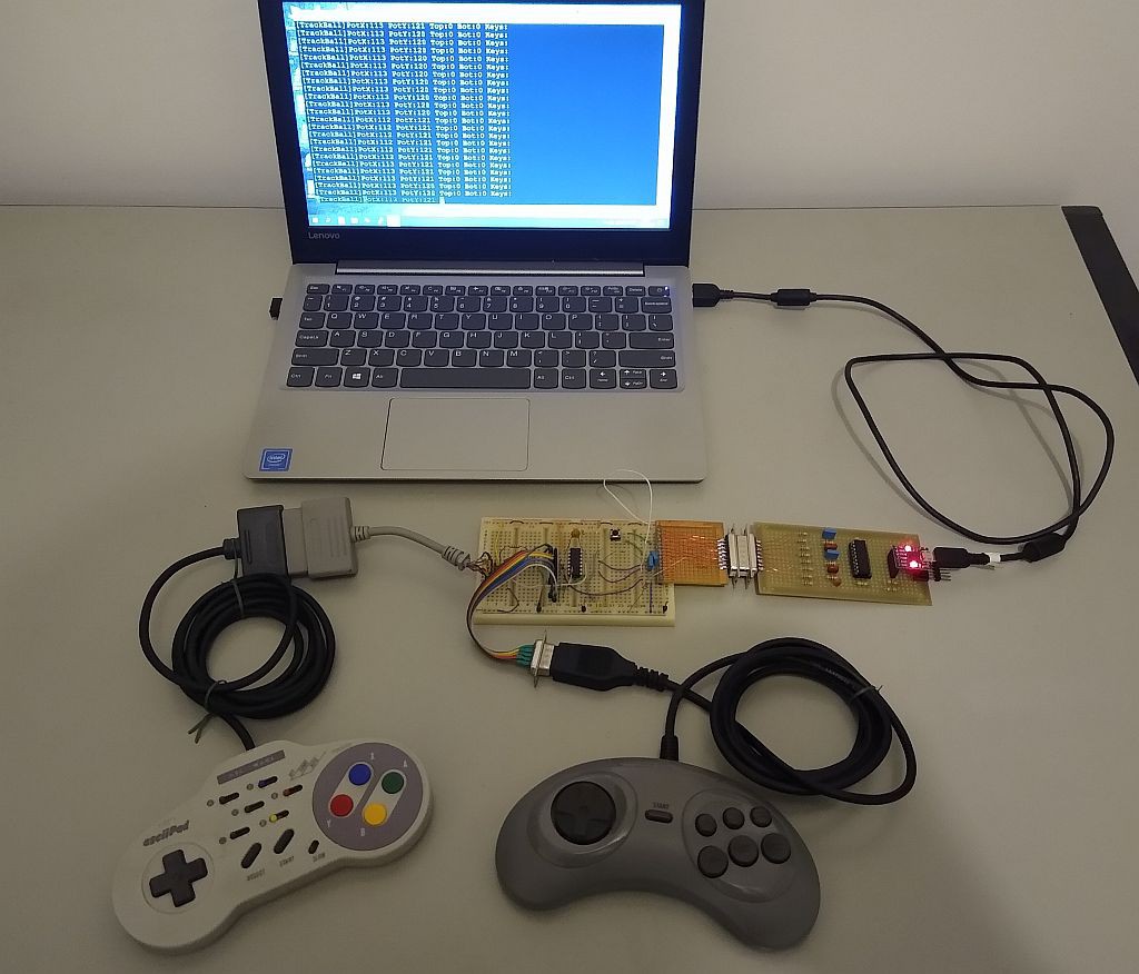
CIRCUIT
The circuit is built around a PIC16F628A. This microcontroller was chosen over an AVR because of the dual analog comparator with adjustable voltage reference, that can be set to simulate different ViH threshold voltages of POKEY chip POT inputs. Each pot input has a timing capacitor of 47nf, a series 1k8 resistor, and an extra 1nf capacitor just like the POT inputs of the POKEY chip in Atari 5200.
8 pins of the PIC are used to read the keypad. Each line is activated (held down) at a time and the rows are read one horizontal line time later (64us).
Top and Bottom buttons are read and all the values are printed at the serial...
Read more »


 Dr.Stone
 Nick Sayer
 NNNI
NNNI
 sjm4306
very nice! Also check out my similar project for more advanced dual port and LCD screen with additional buttons for start/select/etc.. found here: https://hackaday.io/project/177671-atari-5200-controller-to-usb-adapter-2-ports