UTSOURCE
Here we will see how the basic actions (mainly switching action) of a power MOSFET like IRFZ44N and IRF9540 works with the microcontroller generated signals along with a load and how the switching operation is carried out without any circuit hazard.
We will use a 12 V LED Set for our Load purpose to the switching circuit and below is a diagram of breadboard where the load and the MOSFET are connected.
Introduction to IRFZ44N

The above mentioned MOSFET IRFZ44N has a Ultra-low on Resistance along with the dynamic dv/dt rating . The operating temperature of the Transistor is 175 degrees Celcius and some of its specifications are given below .
- It shows fast switching operation
- It is a Fully Avalanche Rated MOSFET
- The device is a completely Lead-free device
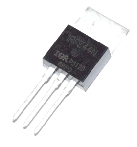
The above picture shows a physical description of the IRFZ44N Power MOSFET.
Now we dill make our circuit for the simulation of the Switching operation and for that please follow the steps below.
Firstly, connect the battery or power source to the breadboard and connect the 12 V LED Load

Secondly, Just connect the IRFZ44N MOSFET with the breadboard and then we have to connect all the things as per electronics rules.

The circuit connection plays a vital role in any of the electronic operations so we
Now we can proceed to make our own switching circuits just see the below diagram that how a switching circuit acts and please do the connections as per the below diagram.

When the wire which connects the base with a resistor is touched to the ON marked terminal the LED gets enlighted and when touched with the other terminal the LED go to the off-stage so we can perform this small circuit switching operation with the IRFZ44N at home very easily.
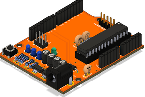
Now we will discuss how to control the switching operation with a microcontroller board like Arduino.
How to use the MOSFET with Arduino
There are just two steps to connect the Arduino with the MOSFET, just follow the steps below.
- Connect the Digital pin (D13) with the Resistor Terminal as discussed above.
- Connect the positive power supply side to the +5V terminal at the Arduino.
Then upload the blink sketch as provided in the Arduino IDE to the board via your PC with the USB
You can also incorporate the PWM Mechanism for the increase and decrease the brightness of the load (LED)
Just upload the example code from the Arduino IDE for the PWM Control
Introduction to IRF9540
It is a p-channel MOSFET and it also works similarly as the previous one, and it can also be used for the switching operations and can be used along with microcontroller boards like Arduino.

The above picture shows a physical description of the IRF9540 MOSFET
For using it with the microcontroller driven approach just follow the below steps and make the circuit just like the below circuit diagram.

The circuit is quite similar to the previous one also just make the circuit and test that.
But as this is the p-channel MOSFET so for the prevention of the circuit damage we have to use a separate NPN Transistor.

So from the above diagram circuit is quite clear.
And now your circuit is ready for the testing now you can upload the blink code from the Arduino IDE and test the system for the circuit debugging.
Conclusion
So we have discussed the MOSFETs that can be used in various circuit applications so for buying them at Best price please visit at utsource.net
 Silícios Lab
 Discrete Electronics Guy
 Gord Payne