Silícios Lab
Introduction
Do you know how the basic circuit of an Arduino works? Every Arduino has a minimum circuit that allows you to put the ATMEGA328p Microcontroller chip into operation. It is known as Arduino Standalone.
In this article, sponsored by PCBWay, we will develop an Arduino Standalone board.
All board files can be downloaded via this link on PCBWay's shared project community.
What will you learn in this article?
- Arduino Standalone Concept
- How to create projects on circuit boards using the Arduino CHIP
- How to Build Your First Arduino Standalone
- How the power circuit for the ATMEGA328P Microcontroller CHIP works
- Arduino board RESET circuit operation
- Circuit for transferring code to the CHIP with external USB-SERIAL converter.
The standalone circuit is widely used by those who want to learn how to transform projects made with an Arduino into a professional board, and you will learn how to do that in this article.
Next, we will show you the step-by-step process for the complete construction of the electronic board circuit.
The Arduino Standalone Board
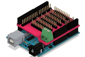
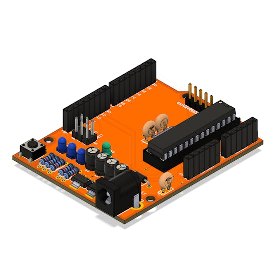
Next we have the electronic circuit of the Arduino Standalone developed. This board was developed with the same dimensions and format as an Arduino UNO.
As you can see in its structure, it has the same access connectors for digital and power pins.
We use the board area to build our own circuit according to the project needs.
See the board structure in the figure below.
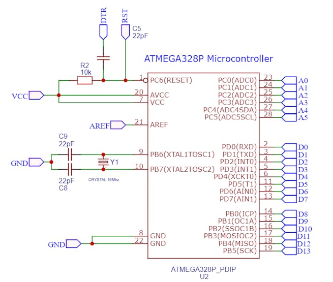
The electronic board circuit was developed from the following electronic schematic.

We will start understanding from the standalone circuit. After all, what is the standalone Arduino circuit?
Arduino Standalone Circuit
By definition, the Arduino standalone circuit is the smallest circuit that guarantees code execution on the CHIP.
This circuit is made up of 3 elements.
- Pull-Up resistor for CHIP Reset pin
- Clock circuit with 16MHz crystal and 22pF capacitors, and
- +5V power circuit.
These 3 elements form the standalone Arduino circuit and guarantee the execution of the project code.
Below is the circuit structure.
From this basic circuit we can add other electronic elements on the digital pins and develop other circuits.
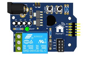
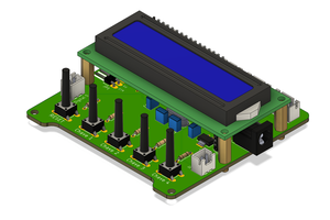
For example, you can, from this circuit, insert LCD display, buttons, relays, and many other elements to the general purpose pins of the CHIP.
This allows, therefore, to create new circuits based on the basic Arduino circuit.
This is how many people develop projects with Arduino and create their own electronic boards to develop some solutions for customers.
In this project we are doing the same thing. We create our own board with the electronic components we want. In this case, we use 3 LEDs connected to the digital pins on the board.
Next, we will present the power circuit that is responsible for powering the Arduino ATMEGA328P CHIP and other components of the circuit board.
Electronic Board Power Circuit
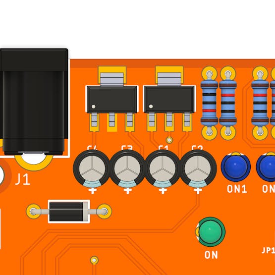
The circuit power of the electronic board is carried out from the Jack connector on the board. See the Jack connector in the figure below.
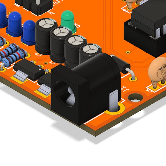
The input voltage for powering the circuit is 7V to 12V, however, we recommend using an input voltage of 7V to 9V. This prevents overheating of the CHIP's that regulate the voltage.
The circuit with the voltage regulators is shown below.
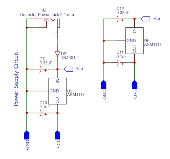
In the figure you can see the 2 AMS1117 voltage regulators and the electrolytic capacitors that form the circuit.
At the jack connector input we have a 1N4001 diode. This diode is used to prevent source polarity inversion and, consequently, damage the project's power circuit.
In other words, this diode ensures that the current is in one direction only. If the circuit is supplied with inverted voltage, the diode will be inversely biased and prevent the flow of current.
After the diode we have the Vin voltage entering the 2 voltage regulators. We have a voltage regulator for +5V and another for +3.3V.
The Arduino UNO has a pin that supplies a voltage of 3.3V to power some devices. We are...
Read more »
 UTSOURCE