 Tyler Bourne
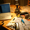
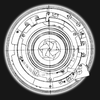
Some time ago I purchased this MC6205 display on eBay. I've been wanting to connect it to my computer and eventually build some sort of project with it. It came with a wiring diagram to connect via parallel. The display has an odd Russian socket on it but I was able to order the matching plugs on eBay. I made a cable but when I powered it nothing happened. I thought my cable was bad since It sure looks bad ;). I designed an adapter board with onboard jack for 12 volt supply and regulator for the 5 volt supply. After soldering and hooking it up nothing happened. I tried again and waited a couple minutes and parts of the screen started flickering then the whole screen flickered a few times and then it came on. It hasn't had issues starting since so it might have been a first time startup issue or an issue with sitting so long. It currently displays a bunch of junk since I don't have the parallel socket to connect it yet.
I found some software to send text to it. It's basic and I hope to reverse engineer the data it's sending to figure out how to write my own.
P.S. The display is currently upside down, since the port is on the bottom.


 kmatch98
 Valrum
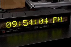
 Frederico Souza Sant'ana
Wooooow! A thing of beauty and a joy for ever.