 Sam Griffen
About
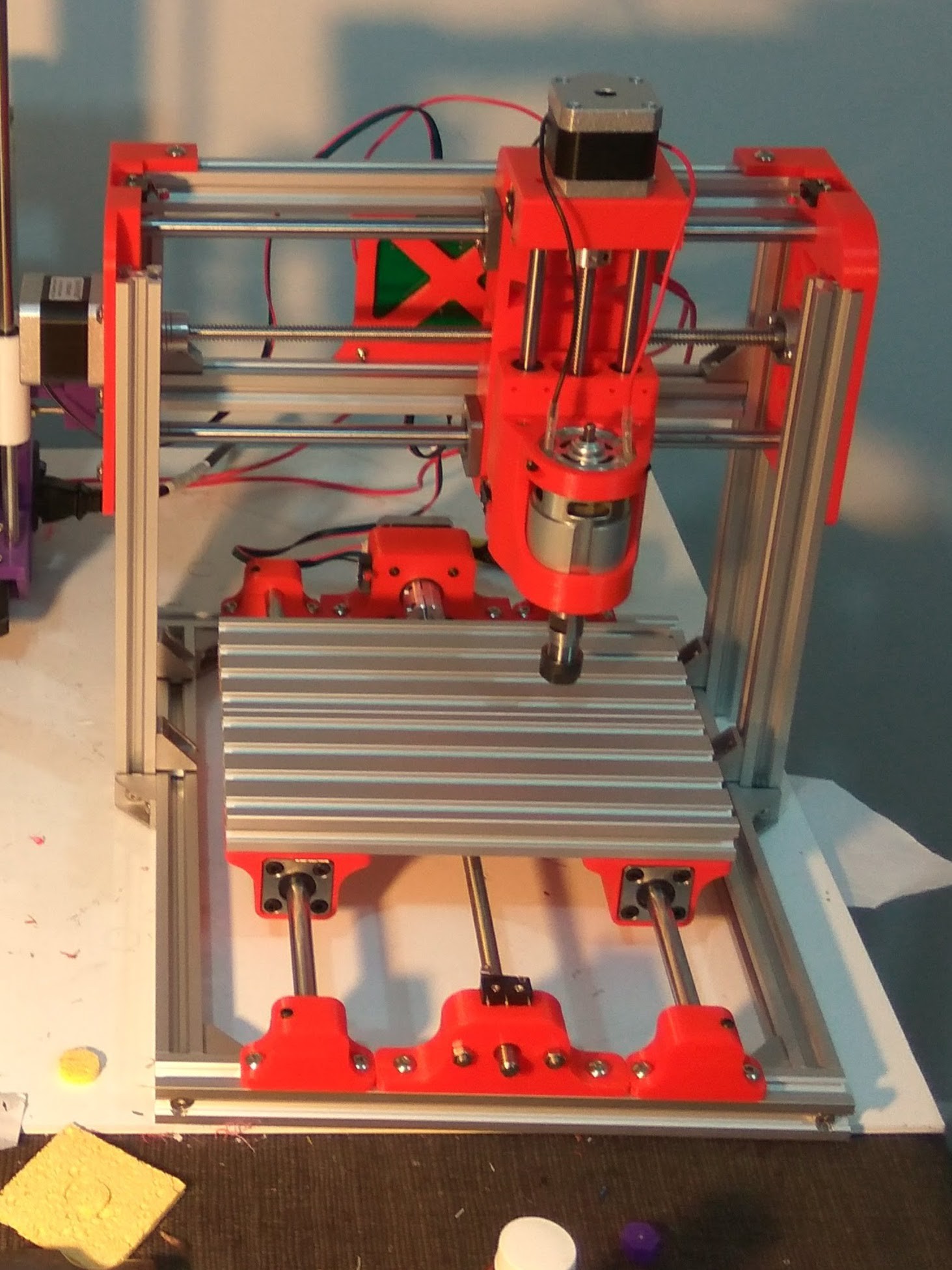
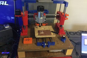
Chad started after a four hour session of soldering a small perfboard, after yet another misconnected wire. Chad is just like every other custom PCB mill around, allowing quick prototype PCB turnaround. He has been designed to be primarily 3D printed, while still remaining rigid and accurate. Alongside this, the design has been made as cheap as I can get it.
Much of the design inspiration comes from thingiverse user pheneeny's AM8 3D printer design, here.
Primary frame components are 2020 aluminium extrusions, with other frame components 3D printed. Motion hardware, and other components are easily available on Aliexpress.
Build
A detailed 3D model of the machine can be found here, in the "Model One" Branch. Models can be exported for 3D printing by right clicking, and clicking export.
It is worth noting that a few parts are missing from this model. Most importantly, the aluminium extrusions are held in place by these little brackets:

These brackets can be seen in the photos of the final build.
To control the machine, a cheap Aliexpress control board has been used. This link is the listing that I purchased a control board from, however this is now a more updated version. This board is powered via an old ATX power supply from a PC. This can lead to issues with the spindle causing a current spike and shutting off the power supply, which is easily avoided by slowly ramping the spindle speed.
Software
FlatCAM is used to generate GCODE from Gerber files. A tutorial by member esaj on the Electronic Unicycle Forum (here) has been incredibly useful in determining settings and whatnot.
BCNC is used to send commands to the machine. GCODE is loaded in, and autolevelling is performed via this software. In future I hope to migrate from this, to a platform that allows me to send GCODE remotely, meaning I would not need to set my laptop up next to the machine.
Results
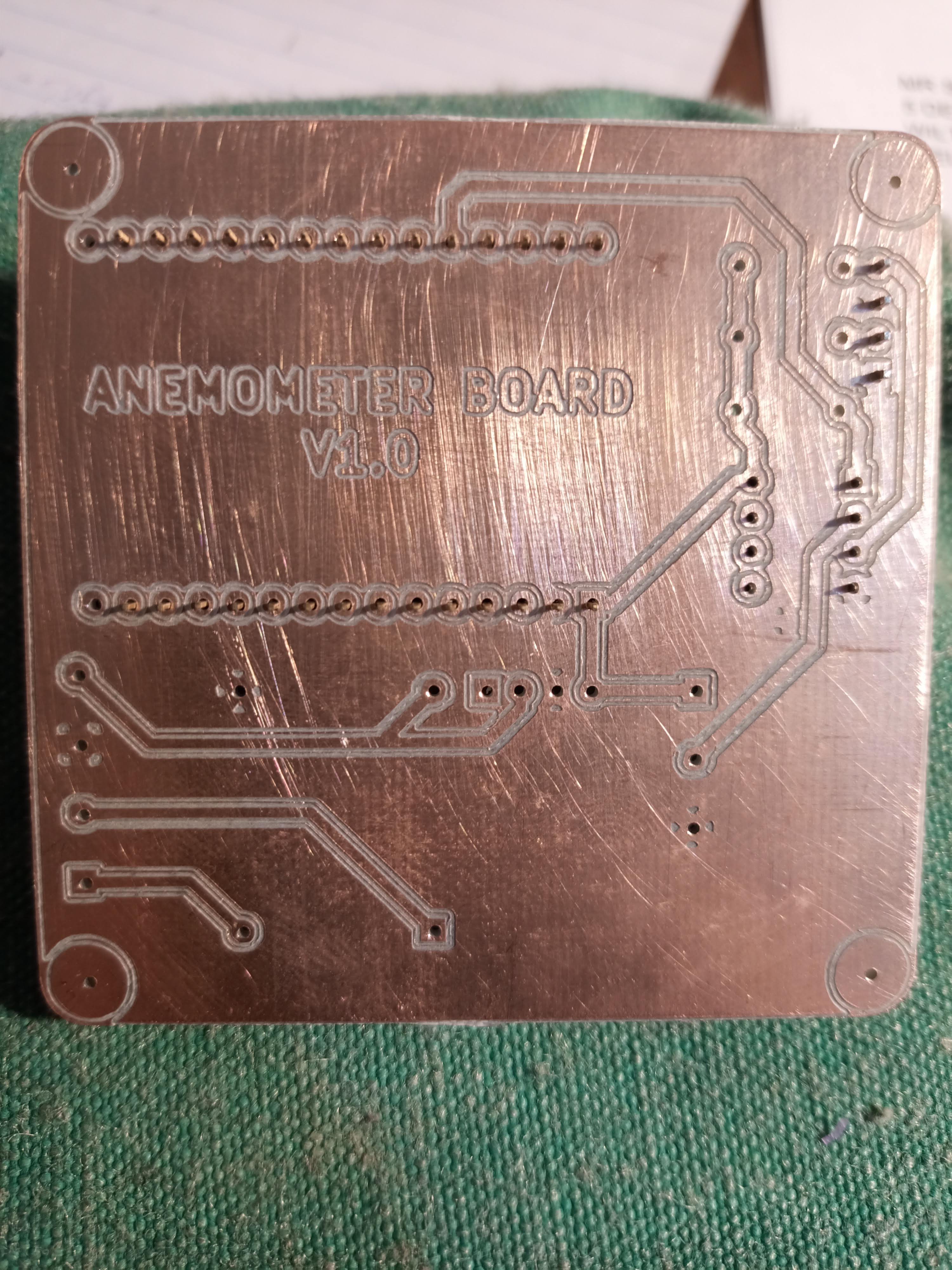
Currently, the results from this machine are a lot better than I imagined I would get on the first revision. Check out the album for some photos of my results.
Thanks to Lindsay of mecha4makers.co.nz (Supplies to New Zealand only). Lindsay cut all the aluminium channels for this machine, and they have been fantastic!
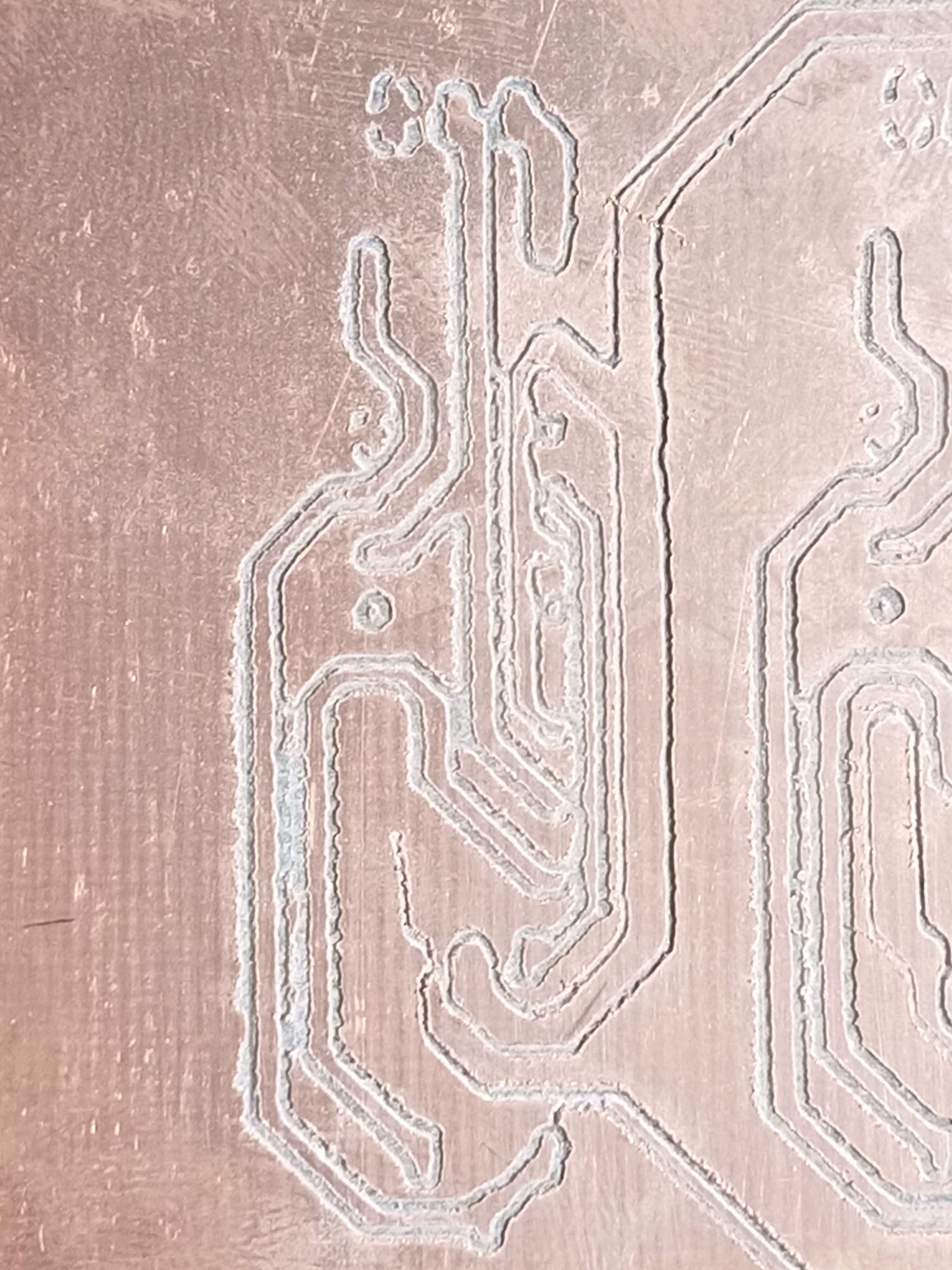
 The culprit of Chad's inability to make nice boards?? I have a couple of solid aluminium couplers in the mail to replace the Z axis coupler, however in the meantime I have printed a placeholder coupler in PETG, and fitted that to the axis. No longer is there play in the tool, it is mounted very rigidly, and the results are very clean:
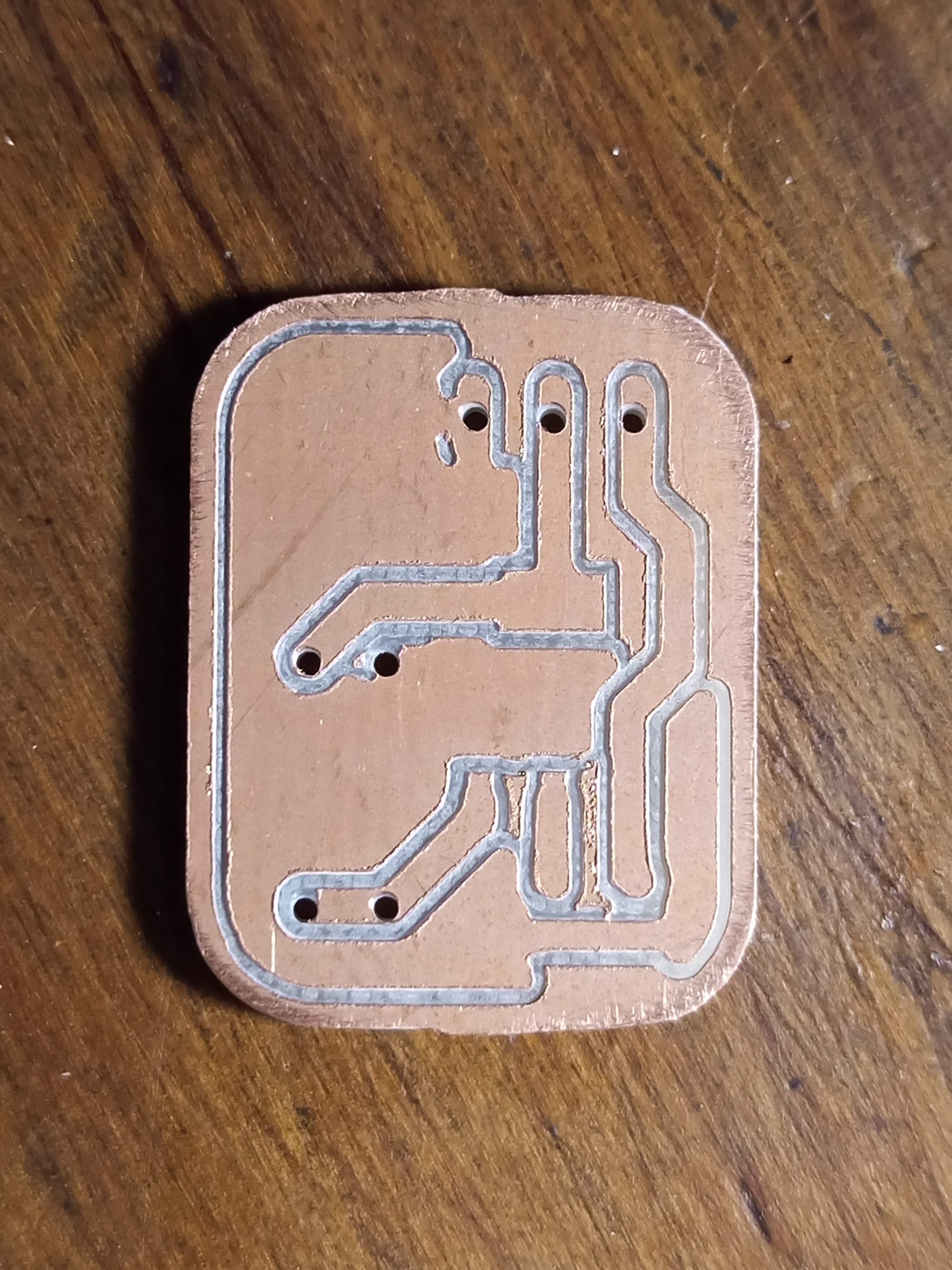
 Thomas Bladykas
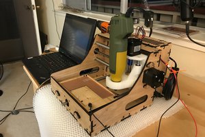
 Timo Birnschein
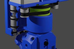
 DTeel
DTeel
great project! have you figured a toolchain to mill pcbs in sections? for example if my workspace is limited to cover only 1/4 of a desired pcb size.
flatcam allows easy placements of indexing/dowels, but i am a bit stuck when it comes to slicing the geometries to mill in parts