 Simon Wirz
Important Note: This Project is still work in progress and will be officially released with a proper YT-trailer.
Current To Do's:
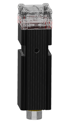
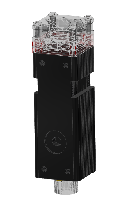
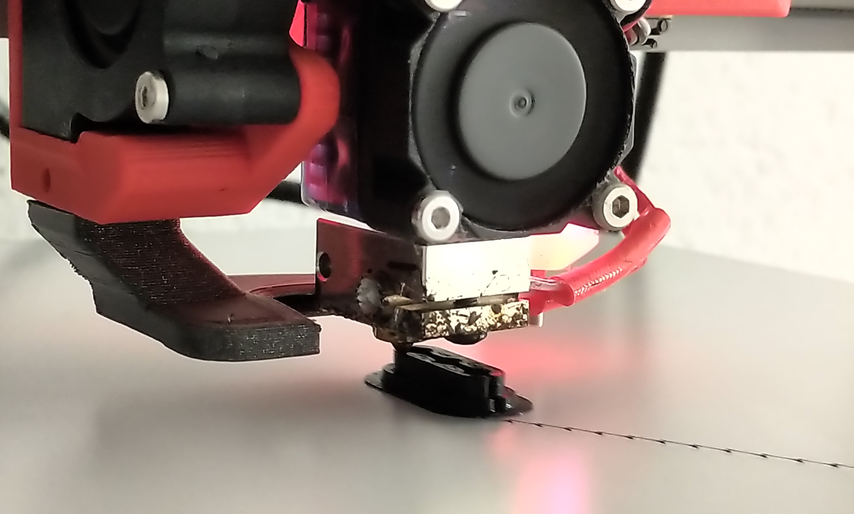
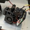
- Testing the directdrive toolhead
- Decision for top-lid/enclosure
- Testing custom tFreeN.g, tPre.Ng and tPostN.g macros
- Calibration tool for the toolhead ((0/0) in center of Bed)
Future goals:
- Camera calibration of the toolhead relative to the docking positions
- Camera calibration to determine the tool offsets quickly and reliable
- PrusaSlicer derivative with full control over different toolheads (plotting, printing, dispensing etc.)
- Custom GUI for the printer
Inspirations:
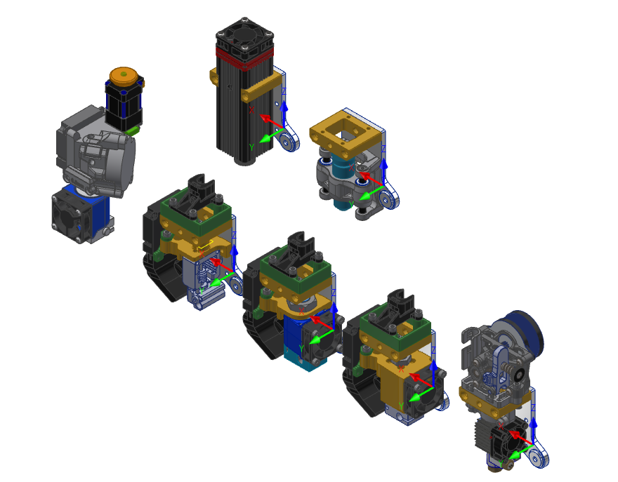
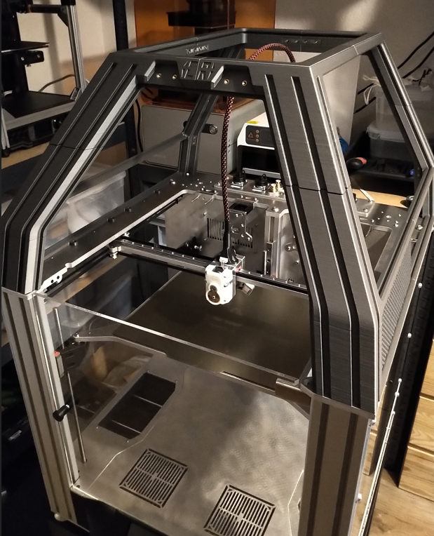
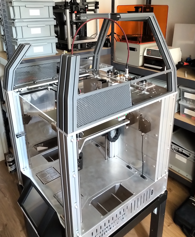
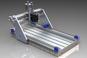
As already mentioned I've used the CAD-files from the released E3D-Toolchanger (https://github.com/e3donline/ToolChanger) for a start. I quickly noticed that the E3D-guys didn't use standard parts such as the standoffs etc.
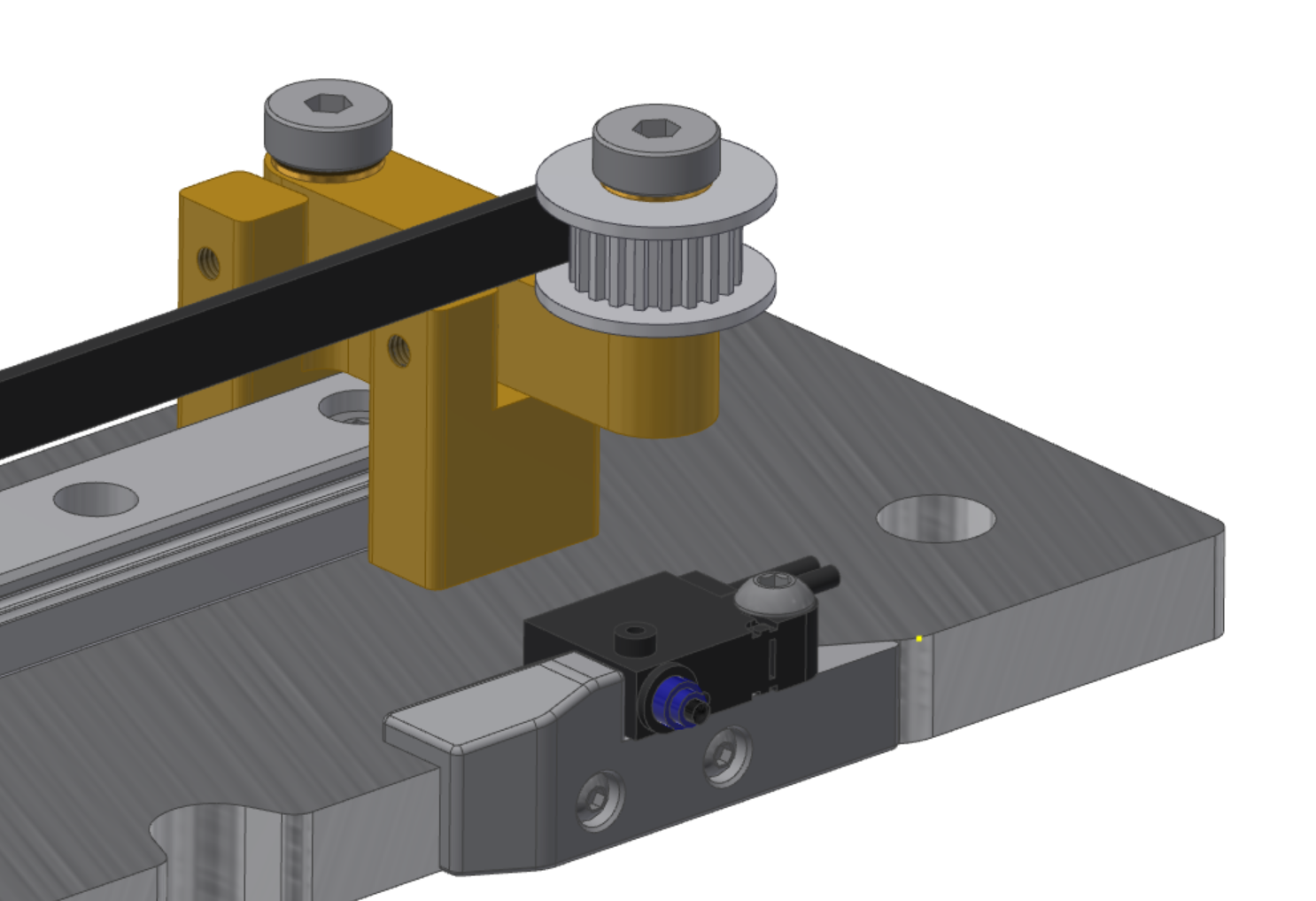
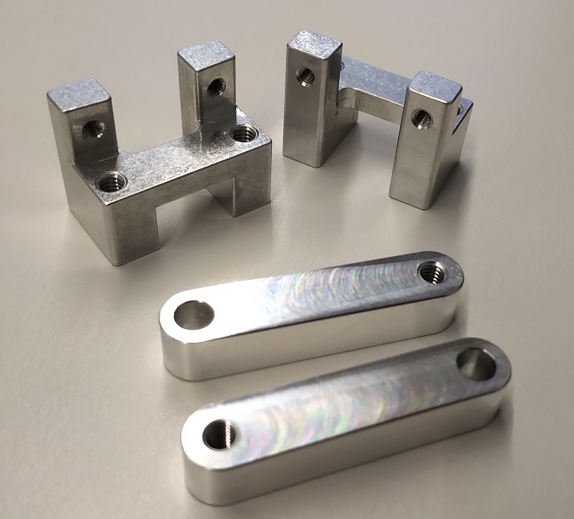
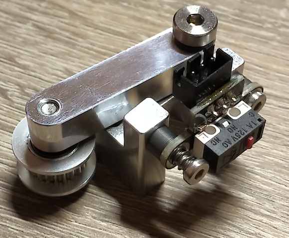
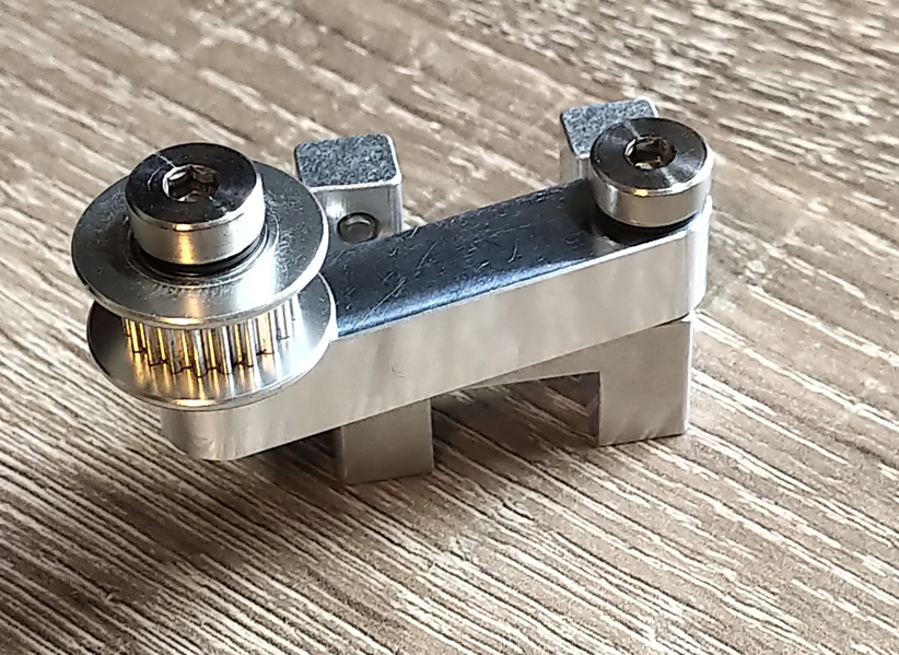
I therefore I started to fully customize the toolchanger with standard parts and heaviliy modified the frame and all of the motion parts.
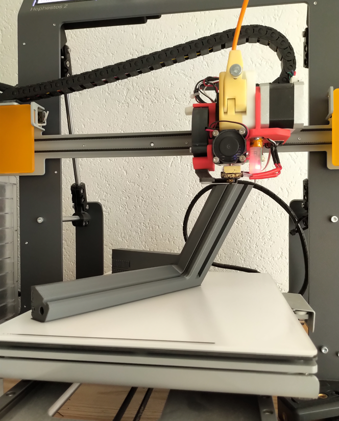
The standard E3D uses a monorail printbed which works just fine but I will be able to perform non-planar-3d-printing (https://hackaday.com/2016/07/27/3d-printering-non-planar-layer-fdm/) with a always perpendicular printing nozzle.
I therfore implemented the kinematic coupled printbed from the jubilee-printer (https://jubilee3d.com/index.php?title=Main_Page) for a first concept. I like the idea of swappable builtplates.
The consequences of a toolchanger:
Personally I think the motion system such as the E3D-Toolchanger is just the start of beeing called a ''toolchanger''. A toolchanger in a more general sense gives you the freedom to easily interchange tools and even procedures (pcb-milling, PnP...). To achieve this versatility the most important features are:
- Defined interfaces/connectors which allow easy toolswap
- Room for periphal devices such as vacuum pumps, additional electronics etc.
- Swappable or modular builindplatform
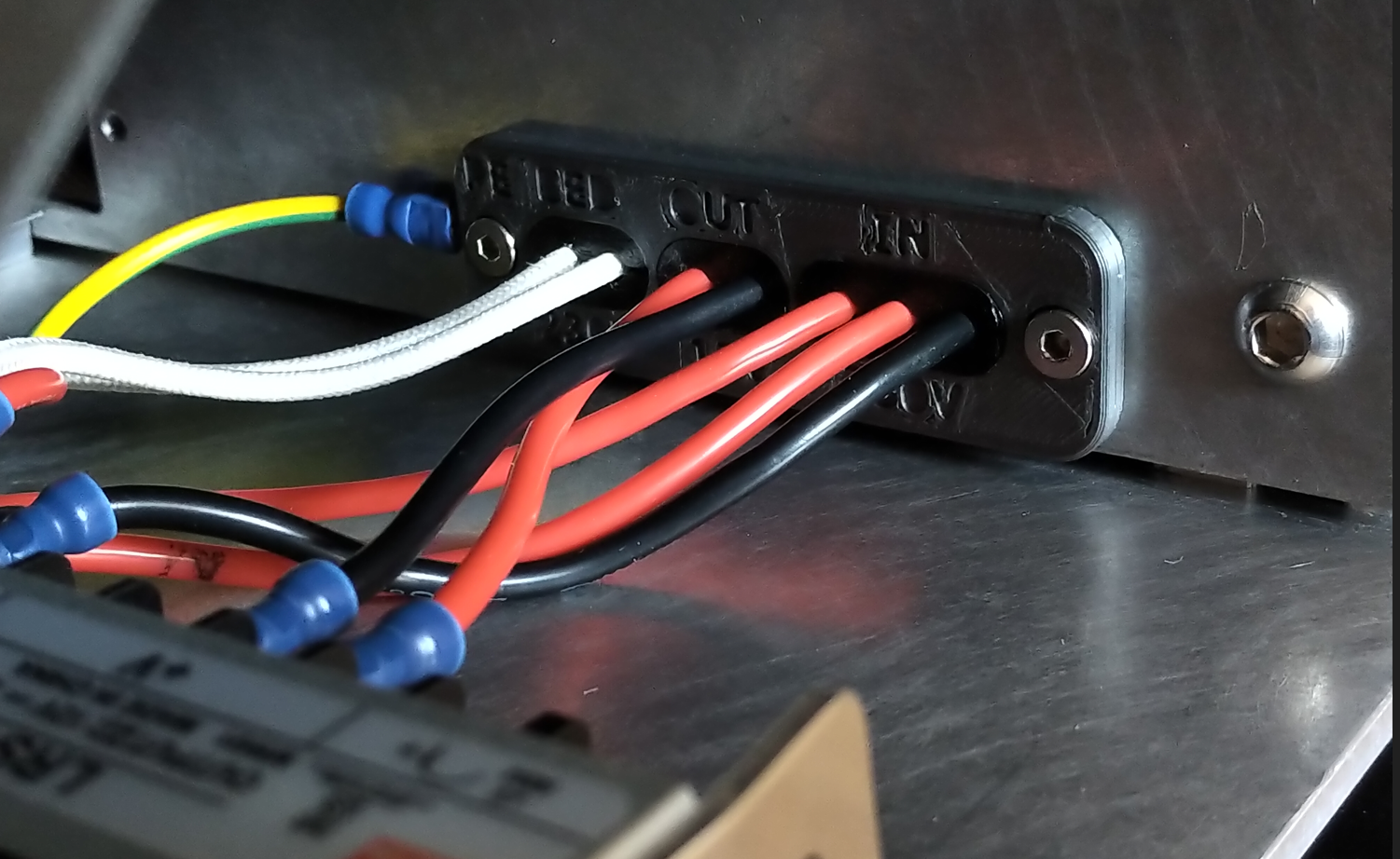
The modular mindset:
There is no doubt that the hurdles are high to create such a system but I think the key is to think and search for overlaps between the functions. An example is the vacuum pump. A common vacuum pumps uses a inlet and outlet connector. One way the pump sucks air in and creates an vacuum (if you block the inlet). On the other hand you have the outlet which blows air out (until you block the inlet). Therefore you can use the pump in the printing configuration to cool your printed part and in the pnp-configuration to create to vacuum and grip the components. To change the configuration you just have to switch between inlet and outlet (manually or with a valve) .
I'm trying to implement this mindset as good as currently possible to reach a high modular toolchanging system.


 Oscar S.
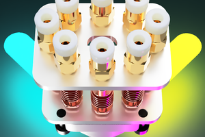
 kelvinA
 Daren Schwenke
Hi, would you be OK to share your 3D Data for modding and getting inspiration how you solved some things? THX