 Bharbour
From the project description of my #GPS Driven Clock project:
There is some debate about the use of multiple parallel capacitors of different values in filters. The parasitic inductance of capacitors mean that large capacitors that are capable of supplying the instantaneous current demands stop looking like capacitors at disappointingly low frequencies. Electrolytic capacitors are really bad in this respect, but the ceramic chip caps suffer from it as well. Lower value capacitors have lower parasitic inductance, so they continue to behave like capacitors to higher frequencies, but won't supply much energy. The most obvious solution to this is to put some smaller value chip caps in parallel with the high value caps in the expectation that the high value caps will supply the instantaneous current while the low value caps will provide low AC impedance to higher frequencies. I have seen several competent people claiming that this idea does not work. I have also heard some people claiming that it does work. I want to see for myself, so the input filter design used here has sites for a range of capacitors.
I started testing this on a complete power filter/regulator board with screw terminal strip wiring. I was using a home built Scalar Network Analyzer from Steven Merrifield ( #Scalar Network Analyser ) that would test up to 30MHz. Connections were made with open wiring to the screw terminal strip for input signals and grabber clips to pick up the filter output. A version of the board was built with just the power input filter since the regulators contribute nothing useful to this test. From the 10KHz to 30MHz testing, no advantage could be seen to paralleling multiple value caps. I wan't confident that testing above 30MHz with open wire input and output connections would give a useful answer so I laid out a small PCB with just the input filter section and SMA connectors for input and output.
All of the capacitors on this board are ceramic caps. The 10uF and 0.1uF caps are XR7 caps and the 1nF caps are C0G caps. There is no DC bias on the board, so the cap values should be pretty close to the designated values.
In order to extend the test frequency range, I used a second copy of the Scalar Network Analyser board that I built up without the Digital Oscillator on board. An external synthesized RF generator was used to supply the excitation frequency. The external oscillator is controlled via the GPIB interface and a version of the Labview code that I wrote (drew?) for the original analyzer has the GPIB control of the oscillator replacing the on-board oscillator control. The Log Amplifiers that convert the incoming voltage signal to dB on the SNA board are rated up to 500MHz, so I ran my tests from 100KHz up to 400MHz
Initial testing ran into problems with dynamic range on the Log Amps. I was driving -7dBm into the filter, and the output of the filter was dropping down to the noise floor of the Log Amps and ADC. After identifying the problem, I re-ran the tests with a higher input drive signal.
Once I got believable results from my SNA setup, I took the filter test board and populated just the 1nF caps and the inductors. Testing showed the high frequency filtering was OK but not great. Next, I added the 0.1uF caps and re-tested. The filter performance improved markedly, both at the low frequencies and higher frequencies. The low frequency performance still needed help though. Finally, I added the 4 10uF caps and retested. The low frequency is now quite good.

Testing in the small to large cap sequence (Ascending order) showed the individual contributions to the low frequency performance. The green and yellow traces in the above plot are done with the same capacitor values installed, the yellow trace was taken with all the caps present before I removed the 10uF and 0.1uF caps and the green trace was taken after...
Read more »
 JasMoH
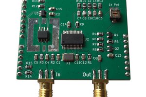
 Jon Klein
 James Wilson