 liugodric
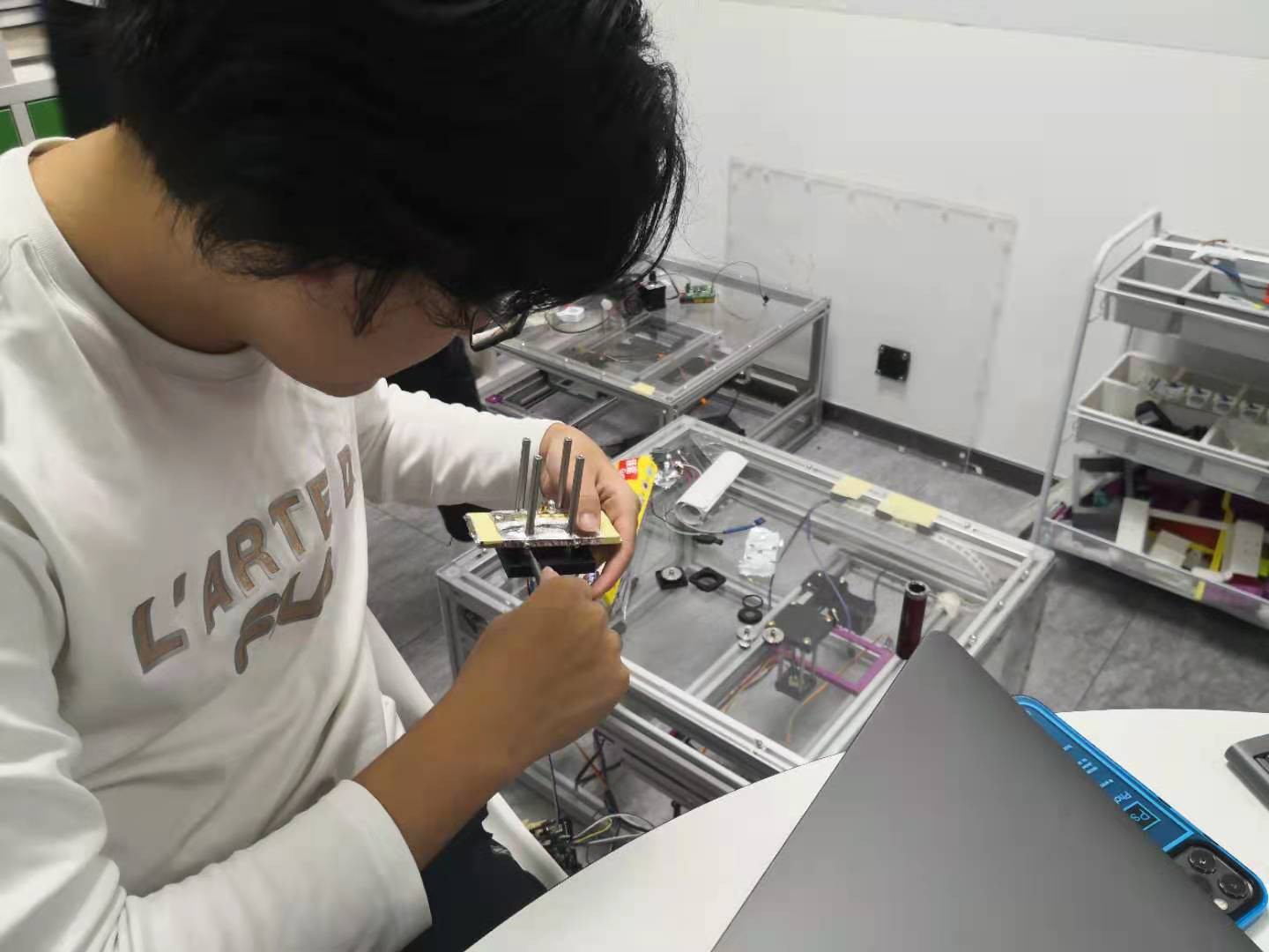
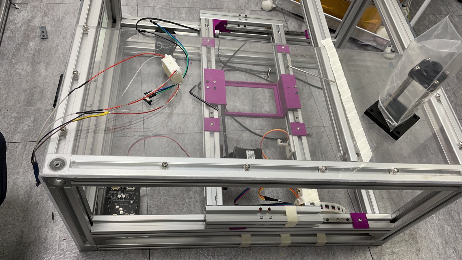
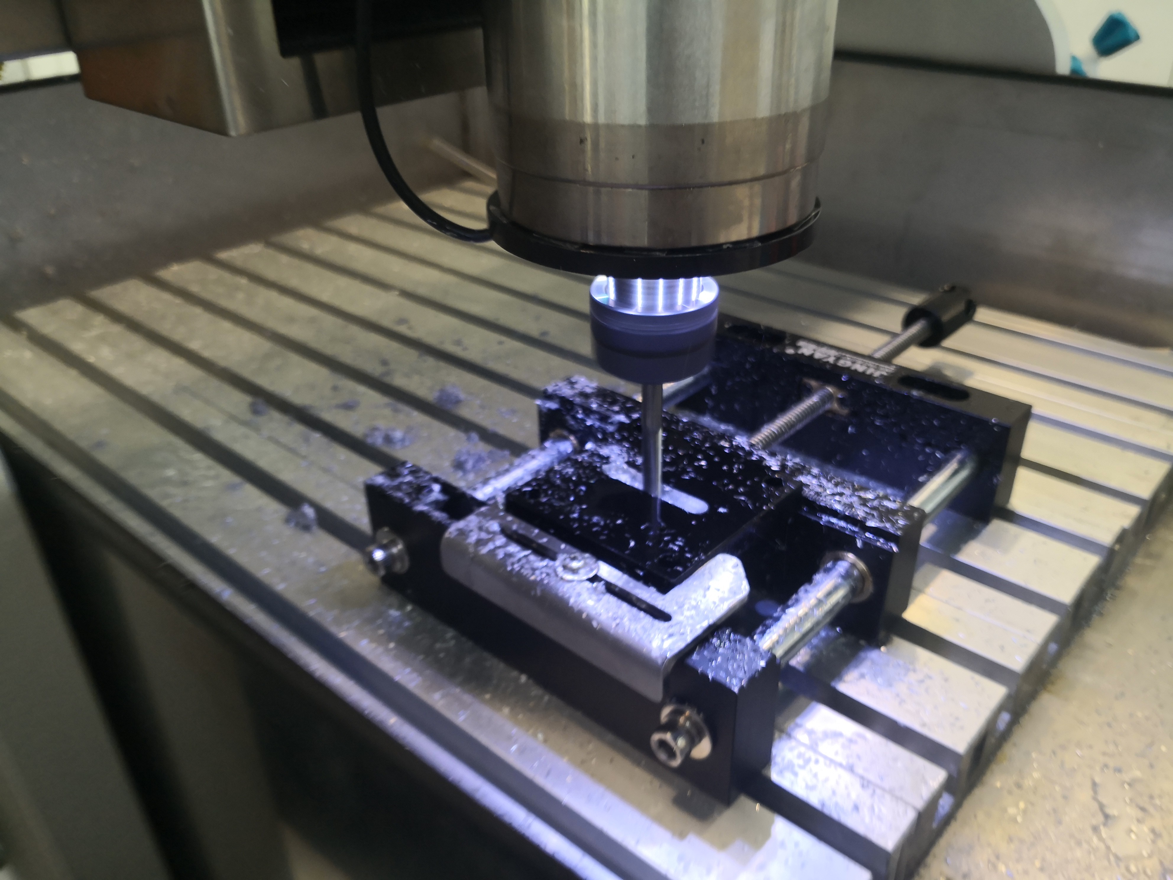
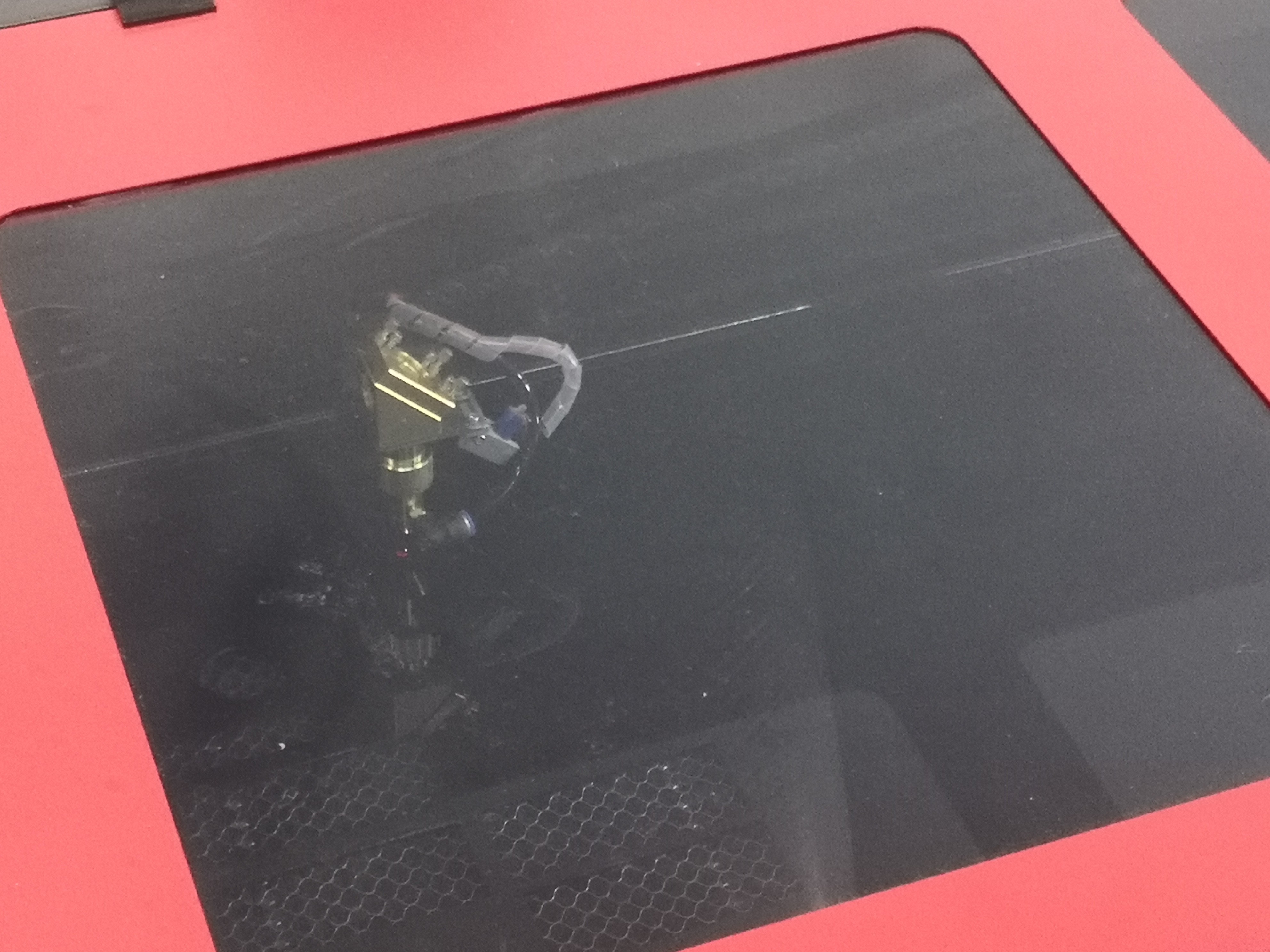
Here, three high school students will report the full process of creating their own low-cost micro plate reader.
0%
0%
Become a Hackaday.io member
Already have an account? Log in.
Just one more thing
To make the experience fit your profile, pick a username and tell us what interests you.
Pick an awesome username
hackaday.io/
Your profile's URL: hackaday.io/username. Max 25 alphanumeric characters.
Pick a few interests
Projects that share your interests
People that share your interests

 Capt. Flatus O'Flaherty ☠
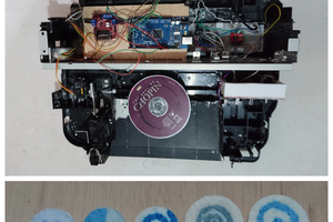
 Guillermo Perez Guillen
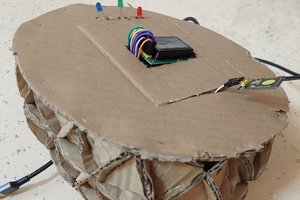

 Kurllyfish
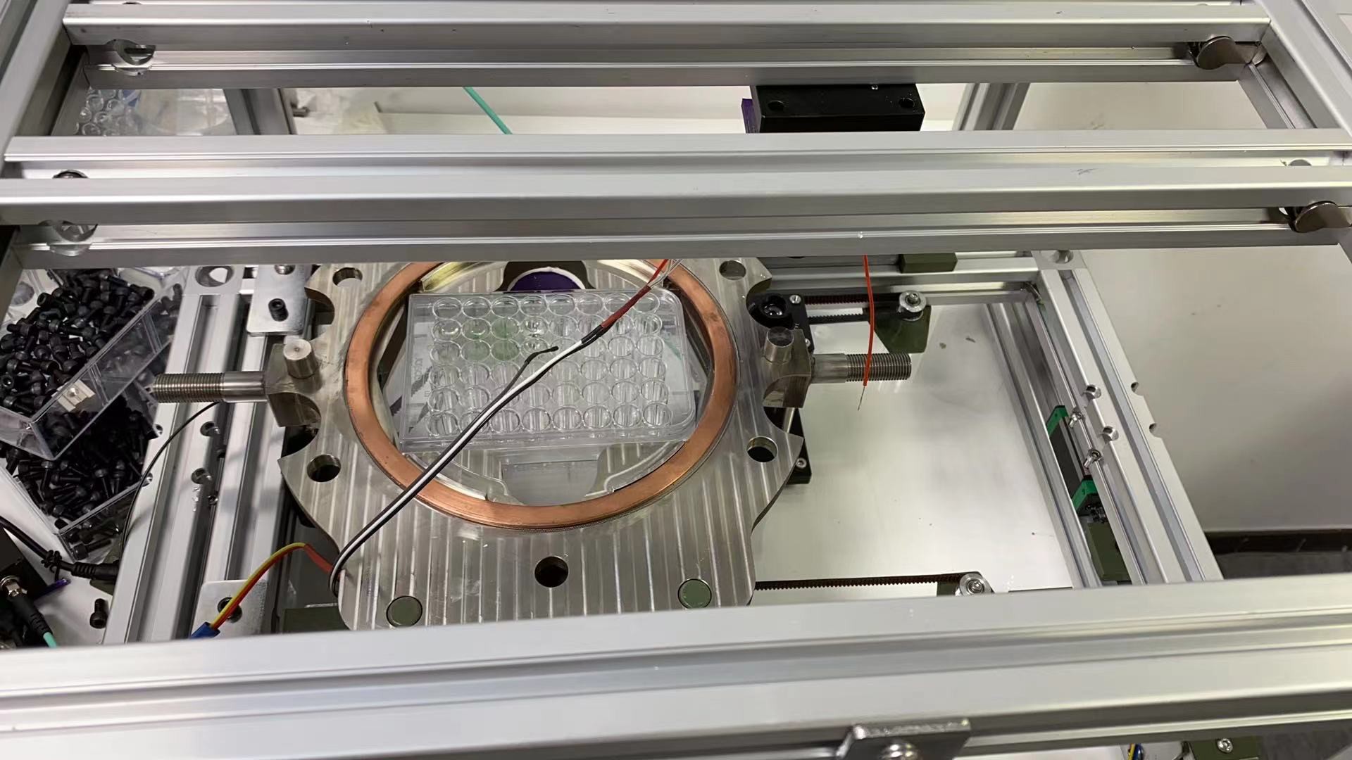
http://labmedical.en.hisupplier.com/product-1196543-Microplate-Culture-Plate.html
Hi, here is a link to the image of a "Micro Plate".
They are used as small test tubes in modern enzyme-linked immunosorbent assay (ELISA).It is a fundamental tool in modern medical testing.