Close
0%
0%

Homemade Operational Amplifier

Homemade simple operational amplifier module and an audio amplifier using it

Similar projects worth following
Operational amplifiers (op-amps) are commercially available as monolithic ICs and are widely used as the basis of analog circuit elements. In 2010, I built my own simple op-amp with discrete transistors to properly understand the principle of the op-amp and experience the operation of the transistors, which allowed me to study the behavior of differential pair transistors and complementary emitter followers. Then I built a practical audio power amplifier with the homemade op-amps. In 2021, I decided to reproduce this op-amp module and publish it.

1-1. Simple discrete op-amp

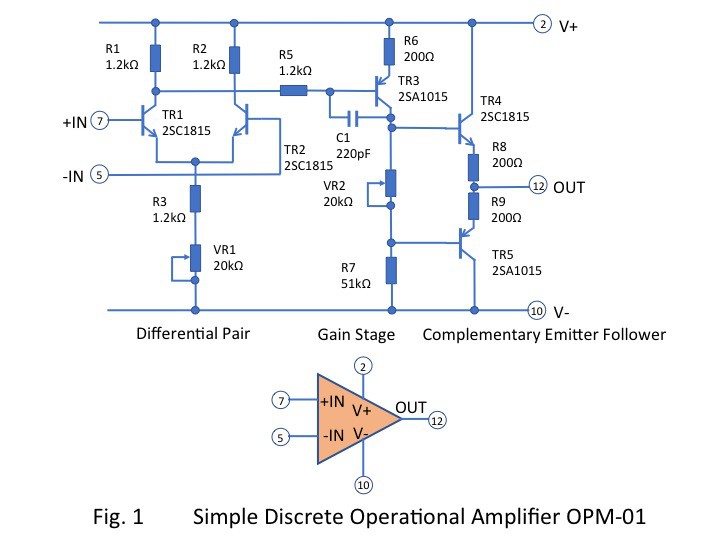
The inside of a commercially available op-amp consists of many monolithic transistors, but in this case, I decided on a circuit with only five transistors to make the operation as simple as possible as shown in Fig.1. The transistors used general-purpose NPN and PNP complementary pair transistors. This project used bipolar transistors, but an example of my own work using CMOSFETs is presented in another project CMOS Homemade Operational Amplifier. I thought I had achieved at this circuit configuration by my own ingenuity, but when I searched the net again now, I found several similar circuits published. I guess the limitation of five transistors means that anyone can reach the same solution.

1-2. Differential pair

Shown in Fig.1, the differential pair consists of two transistors TR1 and TR2. Offset adjustment of the entire operational amplifier is done by VR1. This VR1 needs to be a multi-turn type. In commercial operational amplifiers, this is not necessary because each individual unit is laser-trimmed.

1-3. Gain stage

The gain stage consists only of a transistor TR3. The capacitor C1 is for phase compensation and is set to a large value for stability. If C1 is not used, a frequency characteristic of GB product = 4MHz can be obtained, but it may cause micro oscillation.

1-4. Complementary emitter follower

The output stage of this op-amp is an ordinary complementary emitter follower by TR4 and TR5. This stage is no voltage gain but has current boosting. The VR2 is used to experiment with different biases to see the crossover distortion.

1-5. Results 

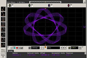
Figure 2 shows an example of a non-inverting amplifier configuration and Fig. 2-1 shows input/output waveforms of the measurement . The oscilloscope's upper signal is 10kHz 280mVp-p sine wave input signal and the lower signal is the output signal. The measured resistances R51 = 5.02k ohm and R52 = 50.4k ohm gave a theoretical gain of x11.04, while the measured gain was x10.96 with a gain error of 0.7%. This was good enough for learning purposes.

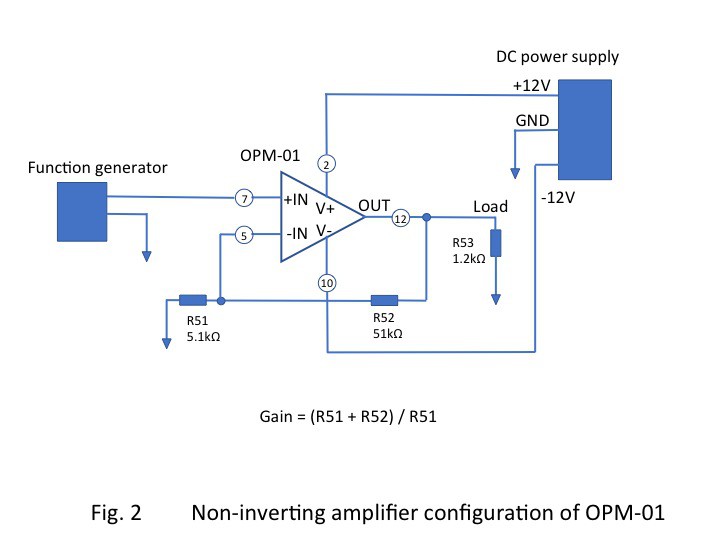
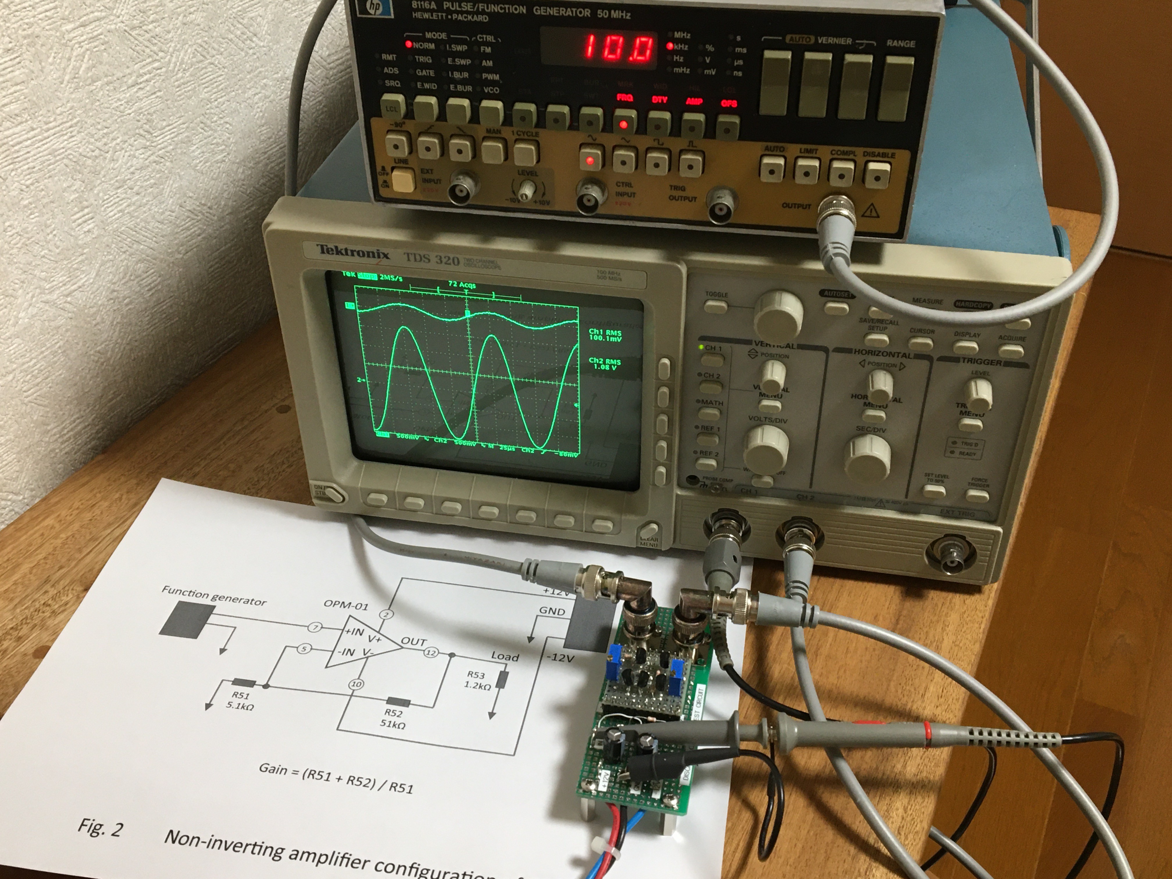
           Fig. 2-1   Measurement of input/output waveforms of non-inverting amplifier configuration

Following video shows an open loop drift,

(00:00) if TR1 and TR2 are thermally uncoupled and the temperature changes by touching either of them, the output voltage can be seen to drift. 

(01:08) If TR1 and TR2 are subjected to the same changes, the output drift will cancel out and you will feel the differential circuit in action.

Adjusting VR2 to zero ohms will cause TR4 and TR5 to operate in class B, resulting in crossover distortion; adjusting VR2 to around 5 k ohms will increase the bias voltage of TR4 and TR5, eliminating crossover distortion.

2. Audio power amplifier

Figure 3 shows a modification to a power operational amplifier. With the emitter follower in Darlington configuration TR6 and TR7 attached, it can drive 0.35A DC for an 8 ohms load. The stereo audio power amplifier shown in Fig. 4 is built with the power op amps. The output power is 1 watt, so I can listen to sound sources such as CD players through the speakers.

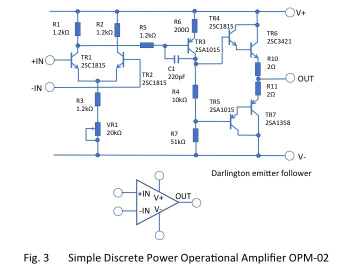
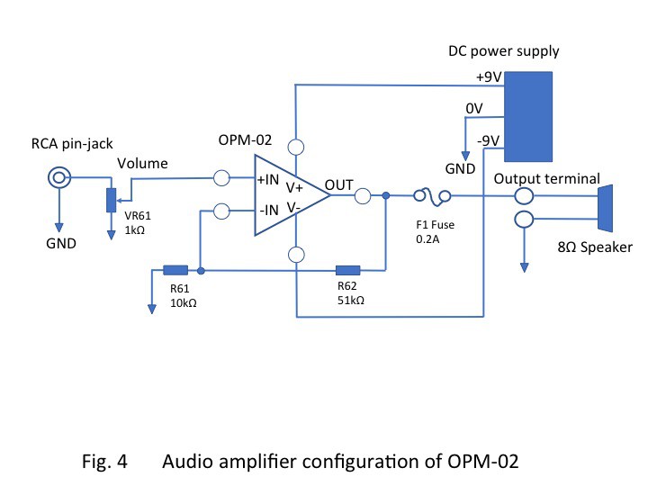
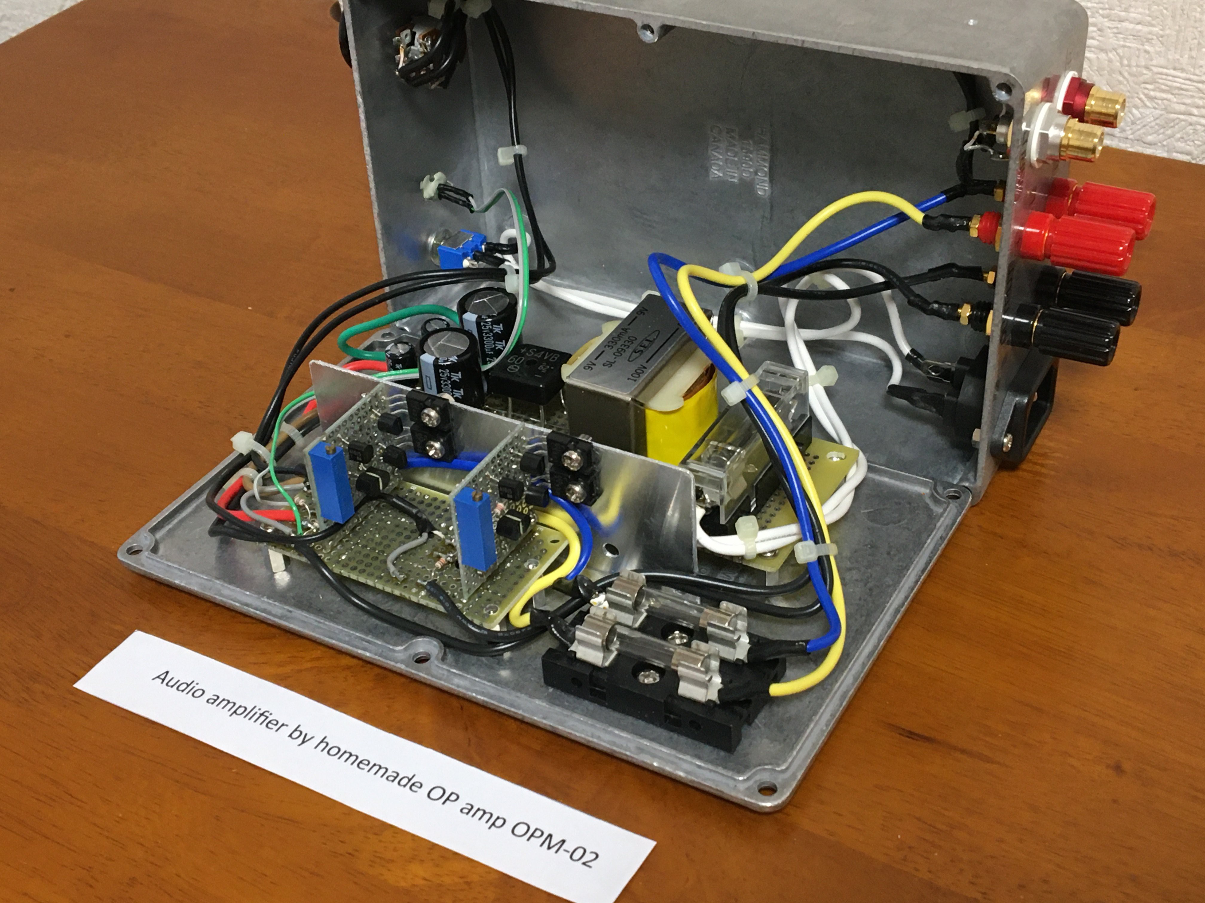
                                Fig. 4-1.     Audio amplifier by using the homemade power operational amplifier OPM-02

(Posted on Jan. 16, 2021)

(Latest revision on Oct. 16, 2023)

IMG_1206.JPG

Non-inverting amplifier configuration test. Gain: x11 Input signal: sine wave 10kHz 280mVp-p (Upper waveform of oscilloscope screen) Output signal: (Lower waveform of oscilloscope screen)

JPEG Image - 2.02 MB - 01/21/2021 at 02:01

Preview
Download

FIG_3_Homemade_Power_OP_amp_OPM-02.jpg

Fig.3 Homemade simple power operational amplifier OPM-02

JPEG Image - 66.12 kB - 01/16/2021 at 04:22

Preview
Download

FIG_4_Audio_amplifier_configuration_OPM-02.jpg

Fig.4 Audio amplifier configuration of OPM-02

JPEG Image - 49.16 kB - 01/16/2021 at 04:21

Preview
Download

IMG_1190.JPG

OPM-02 and inside of the audio amplifier

JPEG Image - 1.80 MB - 01/16/2021 at 04:21

Preview
Download

IMG_1195.JPG

Front side of the audio amplifier

JPEG Image - 1.44 MB - 01/16/2021 at 04:20

Preview
Download

View all 6 files

  • 3 × 2SC1815 Discrete Semiconductors / Transistors, MOSFETs, FETs, IGBTs
  • 2 × 2SA1015 Discrete Semiconductors / Transistors, MOSFETs, FETs, IGBTs
  • 1 × 2SC3421 Discrete Semiconductors / Power Transistors and MOSFETs
  • 1 × 2SA1358 Discrete Semiconductors / Power Transistors and MOSFETs

  • OPM-01 project log

    Mitsuru Yamada10/16/2023 at 08:24 0 comments

    1. The article was first posted on Jan. 16, 2021

    2. Revised on Oct. 16, 2023.

        Added a link for another project 'CMOS Homemade Operational Amplifier' into Chapter 1-1.

View project log

Enjoy this project?

Share

Discussions

Yann Guidon / YGDES wrote 05/20/2023 at 23:07 point

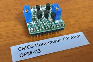
Any comment or advice about the Gain stage ? I think that some circuits use a Darlington pair instead of one.

  Are you sure? yes | no

Mitsuru Yamada wrote 05/21/2023 at 00:44 point

Thanks. It is correct that it will be removed R6 in the gain stage of my circuit because the gain has been turned down.

  Are you sure? yes | no

grifft wrote 11/05/2022 at 14:41 point

I want to use this circuit to replace the op amp used in a voltage regulator circuit, I'm going use it in single supply mode, I don't know if it'll work though.

  Are you sure? yes | no

Mitsuru Yamada wrote 11/07/2022 at 00:41 point

Thank you for your consideration. But this op-amp is quite simplified and has poor output stability with respect to op-amp supply power fluctuations. it also has no Rail-to-Rail characteristics. I think it probably needs a lot of improvement for use with a single power supply.

  Are you sure? yes | no

grifft wrote 11/20/2022 at 04:29 point

I went ahead and used the same parts but in single supply mode. I only added a current mirror on the long-tailed pair. It is able to behave like an op-amp buffer as well as an op amp. It is able to drive a power transistor at its output. I just made sure to add a series resistor from output to the base of the power transistor so that the output stage of the discrete op-amp won't output a lot of current.

  Are you sure? yes | no

grifft wrote 11/20/2022 at 04:32 point

I also added a 1nF cap at the between output and the inverting terminal so that the fluctuation at the output is almost picovolts. 

  Are you sure? yes | no

Joeypc wrote 08/03/2022 at 16:06 point

Will this op-amp work with single power supply with virtual ground ? Tks.

  Are you sure? yes | no

Mitsuru Yamada wrote 08/19/2022 at 03:41 point

Since this op-amp is so much simpler, the usual single power supply connection is not provided an appropriate operating point.

  Are you sure? yes | no

Lightning Phil wrote 01/01/2022 at 09:24 point

Great project.  Have been tempted to include a discrete op-amp in a project for some time.  Seeing this encourages thoughts of building one too.  Good work.

  Are you sure? yes | no

Mitsuru Yamada wrote 01/01/2022 at 11:34 point

Thank you for your comment!  I made this for my own hobby as well as for the training of my colleagues. I tried to keep it as simple as possible so that it would be material for you to enjoy exploring it.

  Are you sure? yes | no

jorpec wrote 12/11/2021 at 16:49 point

Hi

What modifications need to be done on Fig.4 , so i can use the -IN as audio input, so the phase is inverted on the output ?

  Are you sure? yes | no

Mitsuru Yamada wrote 01/01/2022 at 11:16 point

Sorry for the delay in replying. To make the output phase-inverted, instead of connecting R61 to ground you can apply an input signal there. And connect the +IN of OPM-02 to ground. But you need to think about the volume control separately.

  Are you sure? yes | no

Tomas Pavlovic wrote 01/21/2021 at 11:37 point

Your project reminded me this:

https://shop.evilmadscientist.com/productsmenu/762

I have always wanted to build na opamp from discrete parts but haven't find time yet.

  Are you sure? yes | no

Mitsuru Yamada wrote 01/21/2021 at 13:46 point

Thank you for a information. I didn't know there was such a good kit of discrete op-amps. I think it works exactly. My example has only five transistors, so the behavior is not ideal, but it is interesting to watch the behavior of each transistor in a haphazard way for me.

  Are you sure? yes | no

aldolo wrote 01/20/2021 at 18:17 point

basic electronic is soo refreshing. and soo difficult to be honest. much easier slap in an op amp.

  Are you sure? yes | no

Mitsuru Yamada wrote 01/21/2021 at 01:25 point

Thank you. I think so too. About 20 years ago, I decided that without simple experiments, I would lose sight of the original relationship between physics and electronics. Though not rigorously, I started experimenting with just differential pairs.

  Are you sure? yes | no

Isaac Wingfield wrote 01/19/2021 at 05:03 point

Consider connecting R62 to the output side of the fuse, to put its nonlinearities inside the feedback loop, and reduce the output impedance of the amp as seen by the speaker.

  Are you sure? yes | no

Mitsuru Yamada wrote 01/19/2021 at 09:12 point

Thank you for your comment. I did a protection test with fuses, but I had no considering the location of the fuses. In order to make the coil magnetic field of the speaker as linear as possible, It could be use a constant current amplifier configuration with the speaker also in the feedback loop.

  Are you sure? yes | no

Isaac Wingfield wrote 01/19/2021 at 09:30 point

Speakers are rather complex electro-mechanical systems, and a constant voltage drive is considered proper for them. Nearly every solid-state amp on the market has as an output impedance as close to 0Ω as possible (tube amps can't manage that, because of a need to match the output tubes' plate impedance to get a tolerably linear transfer function). If amps were intended to be current sources, their output Z would approach infinity.

  Are you sure? yes | no

Joeypc wrote 08/03/2022 at 16:10 point

Actually, fuse will not affect much about linearity because its inductance is nearly zero. It is recommended to add Zobel filter parallel with speaker of power amplifier to reduce Z on frequencies to speaker.

  Are you sure? yes | no

Mitsuru Yamada wrote 08/19/2022 at 03:52 point

Thanks for the info. The filter may increase stability at higher frequencies.

  Are you sure? yes | no

Paul McClay wrote 01/16/2021 at 16:20 point

Exemplary project & presentation. As a side benefit, the video demonstrates distribution of heat in the transistor after you remove your finger. Appreciated; thanks.

  Are you sure? yes | no

Mitsuru Yamada wrote 01/17/2021 at 01:34 point

Thank you for watching. I found out that the temperature inside the transistor seems to reach its maximum temperature after the finger is removed. When I asked my acquaintances to try it, they were impressed.

  Are you sure? yes | no

Ken Yap wrote 01/16/2021 at 06:36 point

👍 I feel that every student of analog electronics should be required to build an op amp like this as part of their studies.

  Are you sure? yes | no

Mitsuru Yamada wrote 01/16/2021 at 07:56 point

Thanks ! I totally agree with you. I think that the ability to handle transistors, without assuming that the inside of an IC are a black box, will lead to students ability.

  Are you sure? yes | no

MS-BOSS wrote 01/26/2021 at 15:09 point

At my school, we had to design an op-amp on silicon level in Cadence. First as a schematic with required design goals such as slew rate, amplification, offset, output impedance and so on. Then we had to draw it on the silicon and simulate using Monte-Carlo simulations to verify that it was done properly. Also, we had to make sure it didn't suffer of latchup and so on.

  Are you sure? yes | no

Mitsuru Yamada wrote 01/27/2021 at 01:01 point

Thank you. I think it is important to learn design and simulation if students have access to Cadence simulators and other equipment at school. After that, they may be able to send the design data to a semiconductor prototyping process to make an actual device and evaluate it. However, I think that the best way to get a rough idea of actual operation is to build a circuit with a few transistors and observe it with an oscilloscope or other measuring equipment. When I went to school in 1980, there were no simulators or anything like that.

  Are you sure? yes | no

MS-BOSS wrote 01/27/2021 at 18:04 point

Well, the school didn't have money to make the chips. And we also had to build discrete circuits, but it was mostly just following instructions. However, I started making FM bugs, AM transmitters and other RF fun at high school so I didn't learn much about electronics in school, but mostly by myself.

  Are you sure? yes | no

Similar Projects

Does this project spark your interest?

Become a member to follow this project and never miss any updates