 _electroidiot
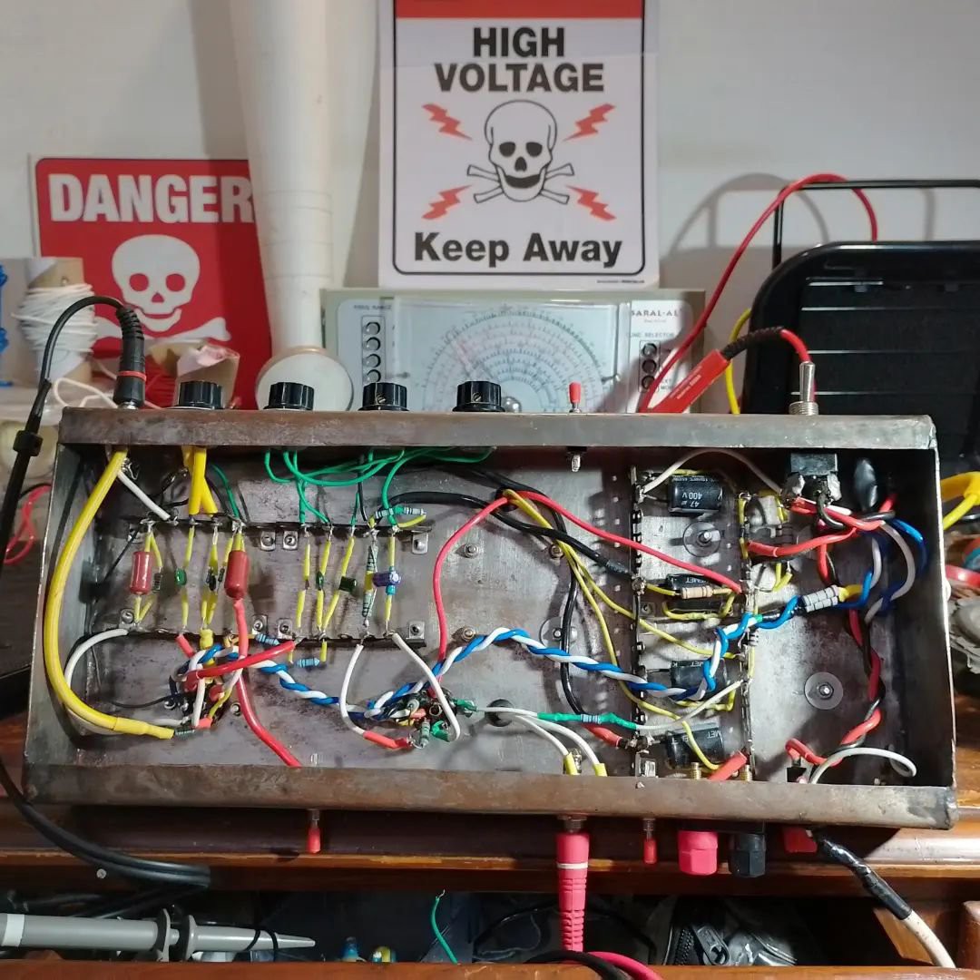
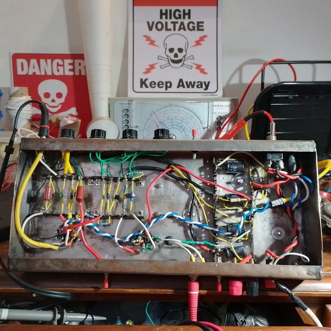
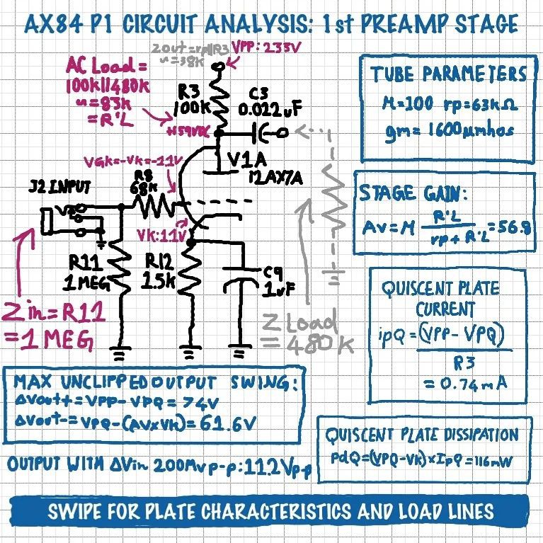
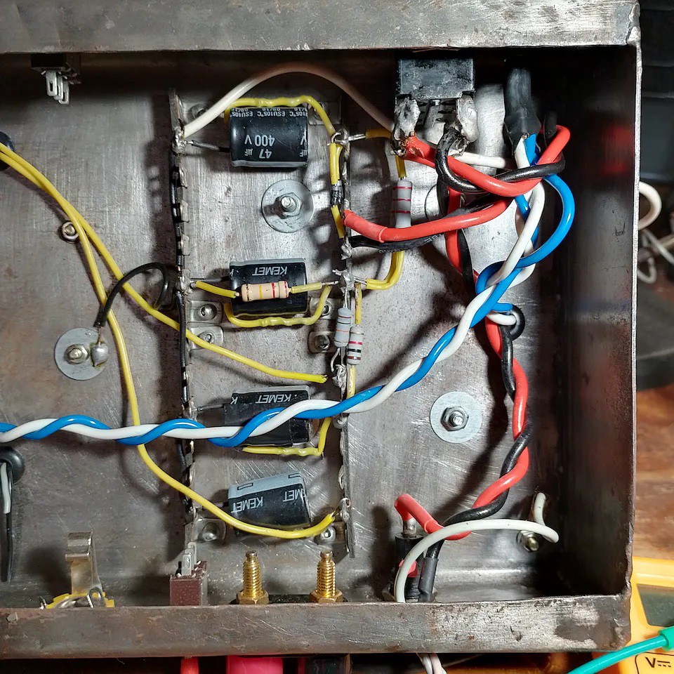
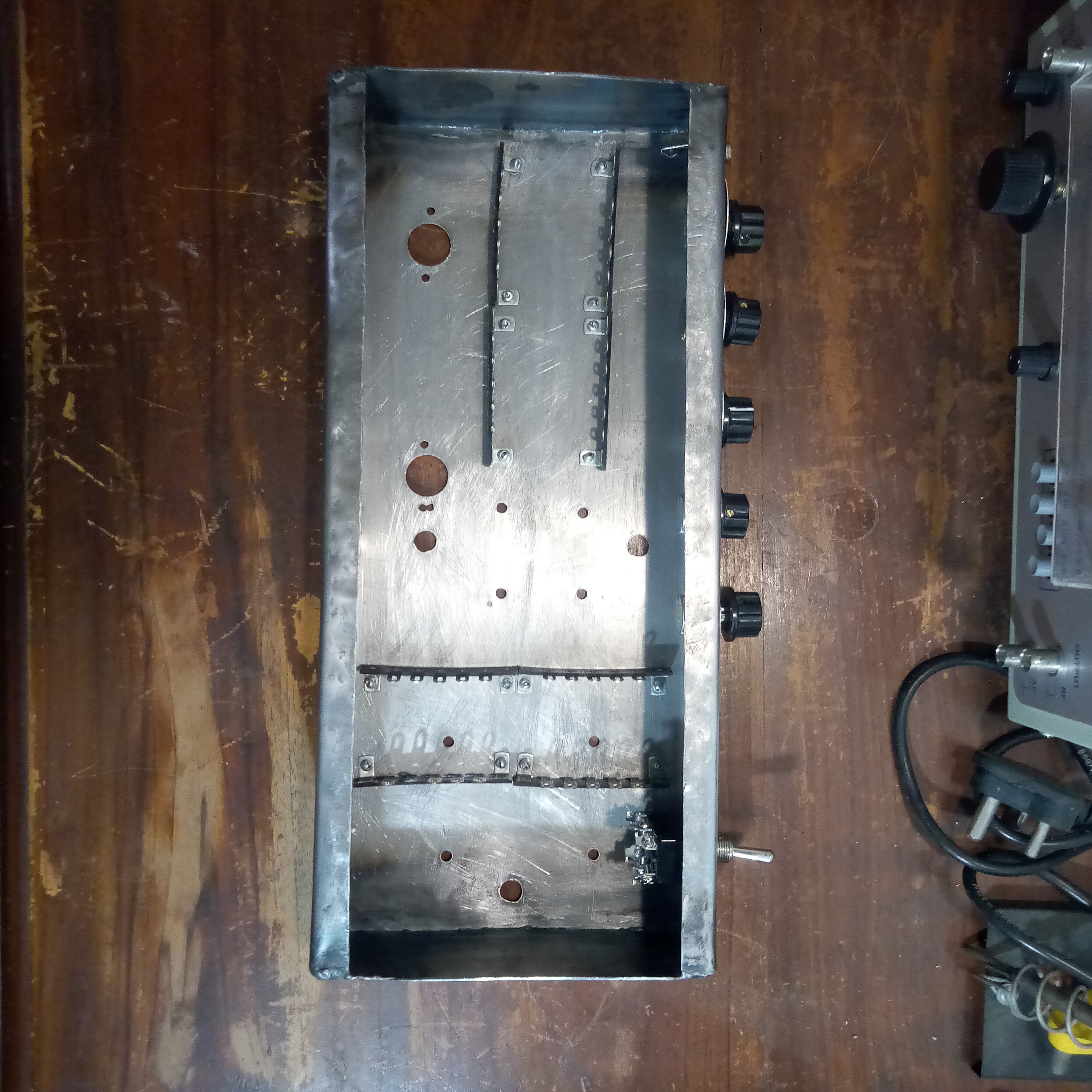
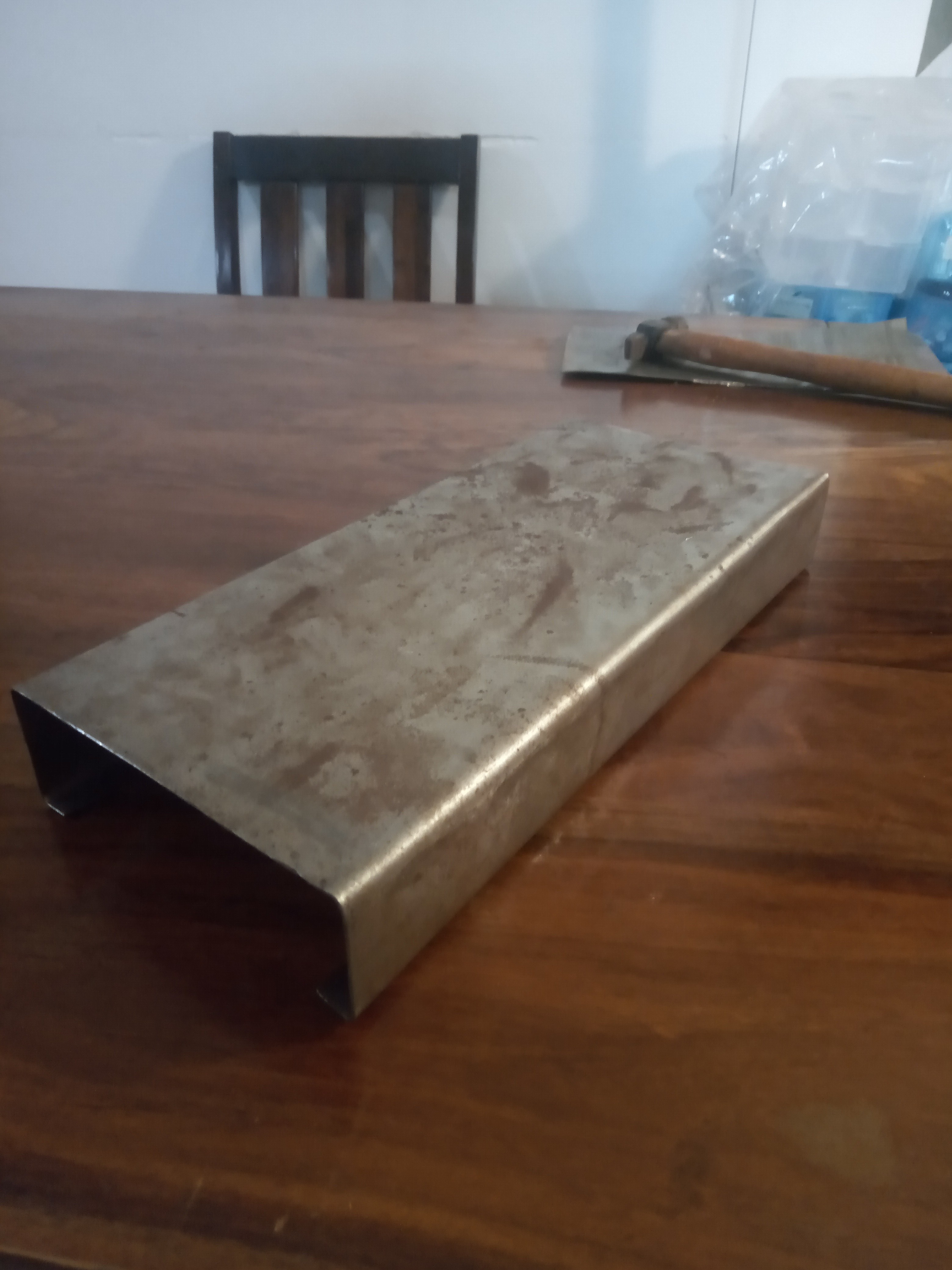
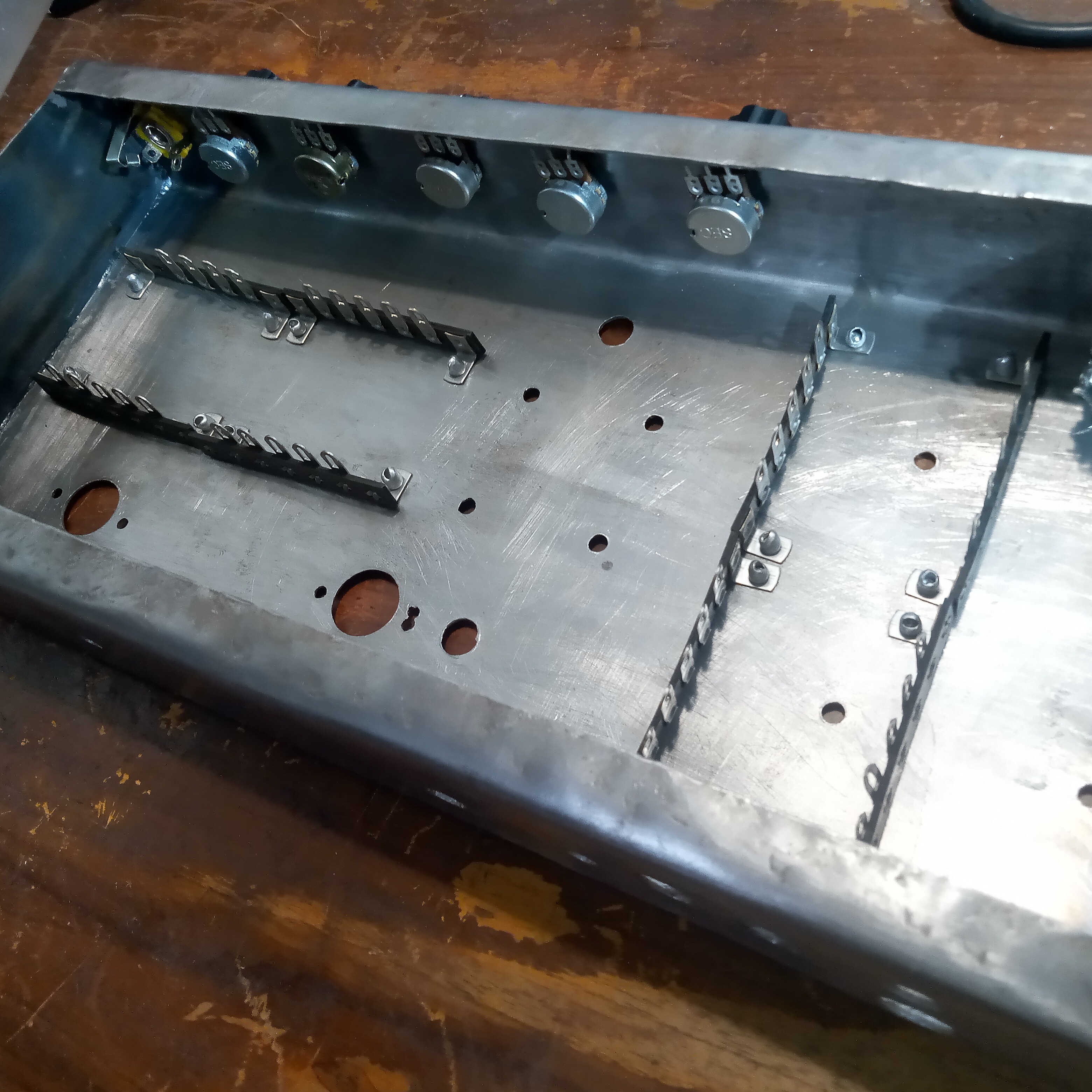
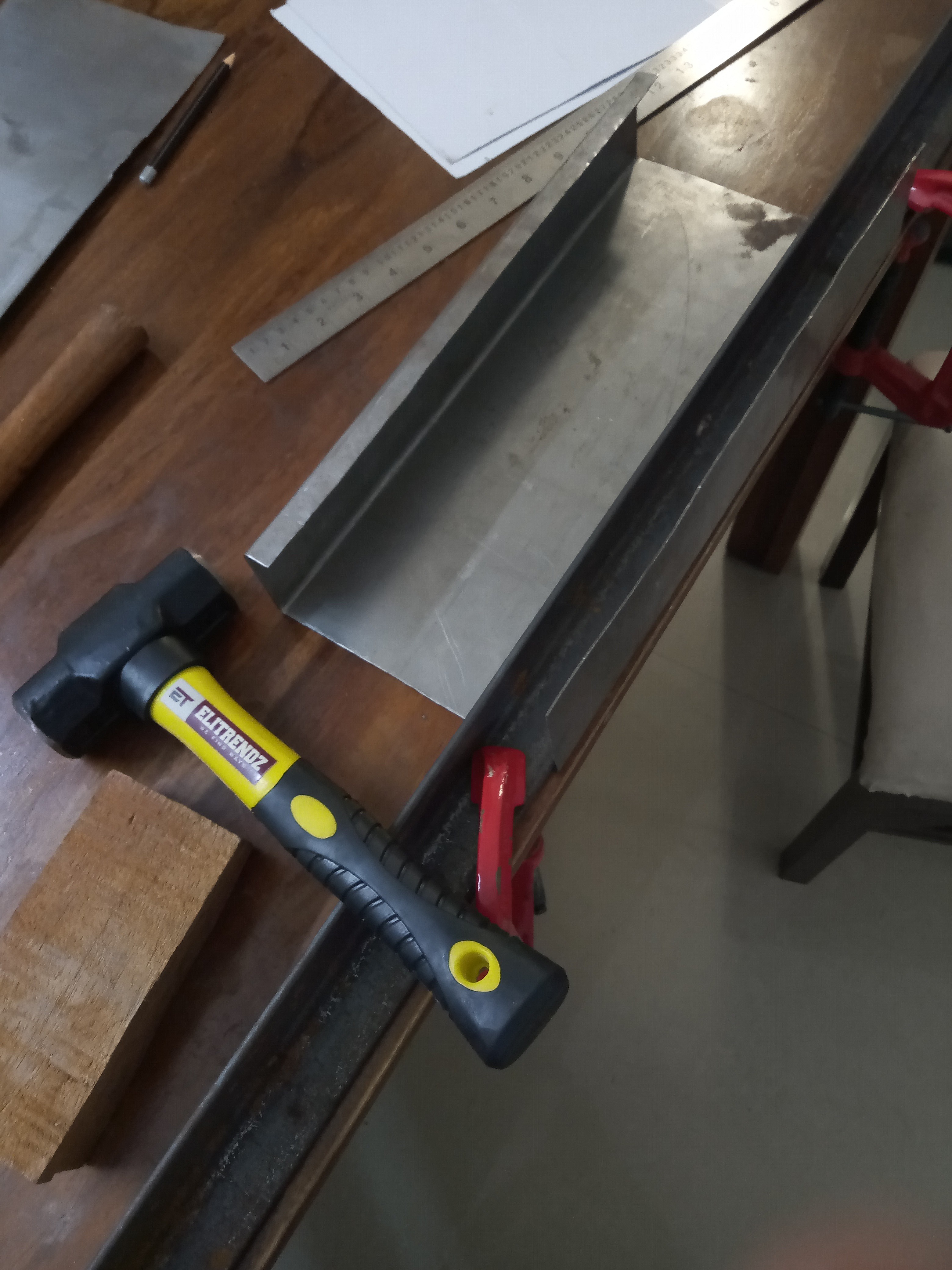
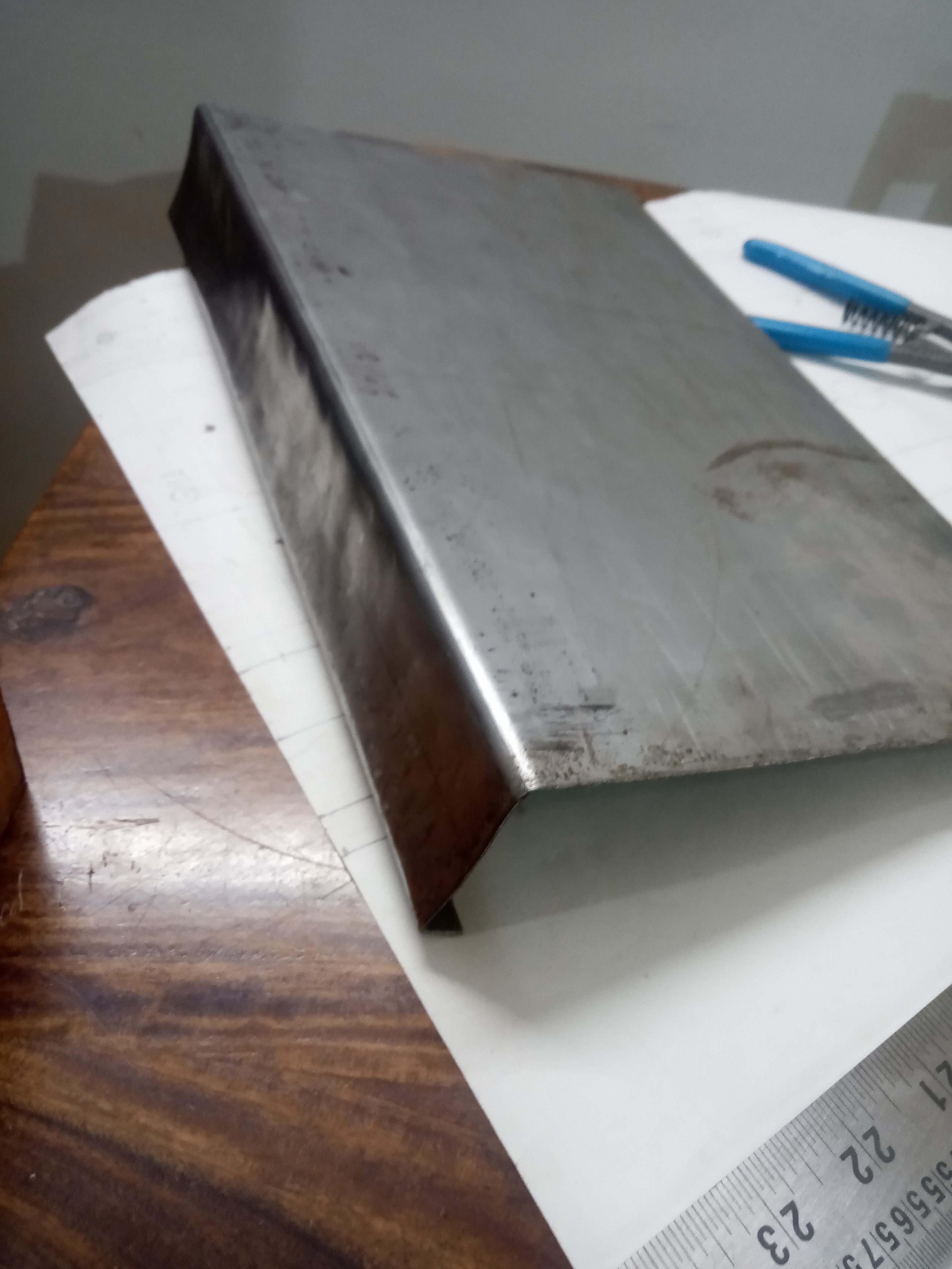
The amplifier was built in a custom chassis that I bent out of a piece of sheet-metal. I wanted to keep things as authentic as possible and avoid using a modern laser-cut or premade chassis. All the wiring is point-to-point on old-school terminal strips. The amplifier circuit is based on the "AX84" project, which takes inspiration from vintage Fender and Marshall guitar amplifiers from the 1950s and 1960s. New old stock made in India "BEL" tubes were used. The transformers were selvedged from a junked 1960s Phillips radio. I tried to analyse each stage of the circuit as I build the amplifier, to further my understand of vacuum tube circuits. Please check out the project logs below for more details. This was my first ever attempt at building a tube amplifier, so it is far from perfect. The goal of the project was education as opposed to building the best amplifier possible, however the amp sounds great and has very low background noise/hiss even compared to some commercially available modern vacuum tube guitar amplifiers. I would like to re-build it someday in a better chassis and clean up the wiring as well.
0%
0%
Dirt Cheap Tube Guitar Amp Build
Building my first tube amplifier, on a tight budget.
Become a Hackaday.io member
Already have an account? Log in.
Just one more thing
To make the experience fit your profile, pick a username and tell us what interests you.
Pick an awesome username
hackaday.io/
Your profile's URL: hackaday.io/username. Max 25 alphanumeric characters.
Pick a few interests
Projects that share your interests
People that share your interests
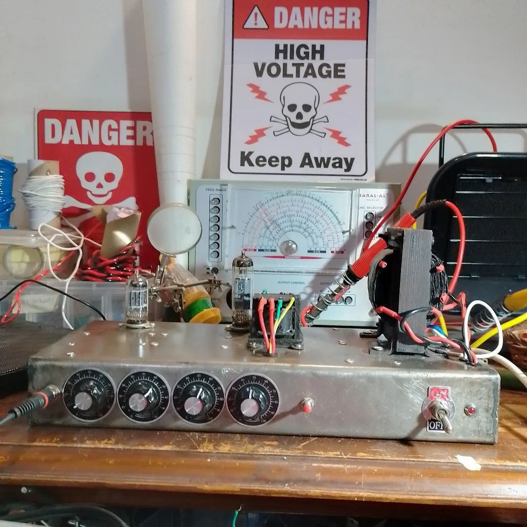
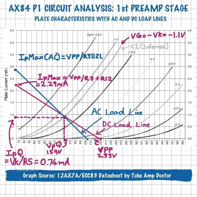
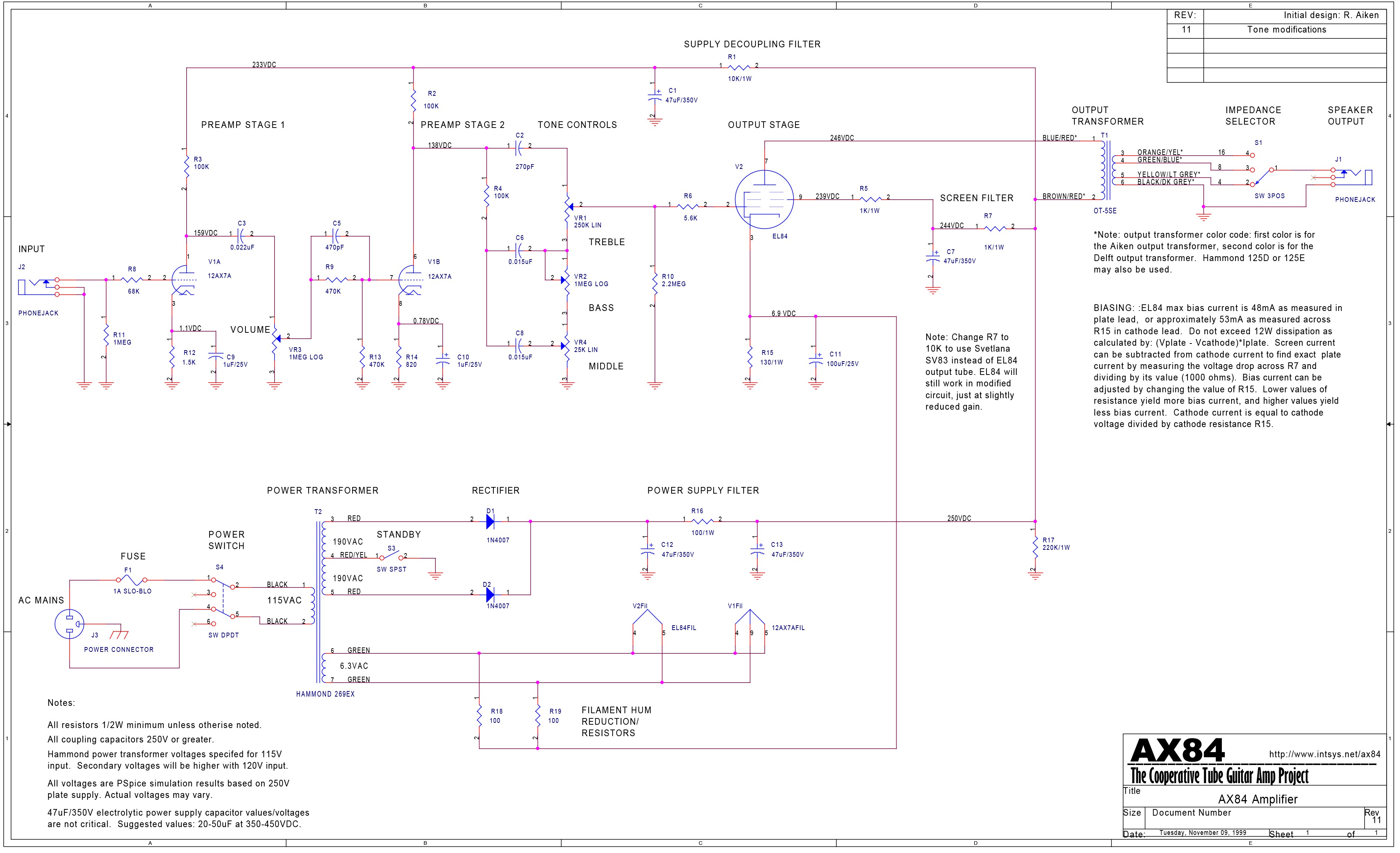 Building a tube amp has been a dream of mine for a couple of years. in 2022, I was finally able to start my build which is now complete. I was on a tight budget, and my main goal was to learn about tube/valve amp construction through this build, and not necessarily build the best possible amplifier. Thus I decided on the AX84 guitar amp circuit found online, more details are available here:
 Mitsuru Yamada
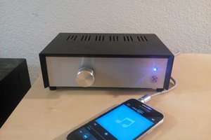
 Szoftveres
 Chris Johnson
 Boolean90
Looks great, sounds great! Thanks for documenting the design and build so well!