Ben Steer
Choosing the features
I like to start a design by making some high-level decisions about what features it will have. There’s no need to be too specific at this point, we’re just setting our overall goals for the robot.
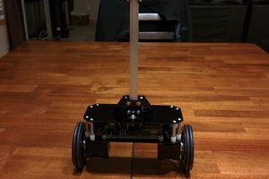
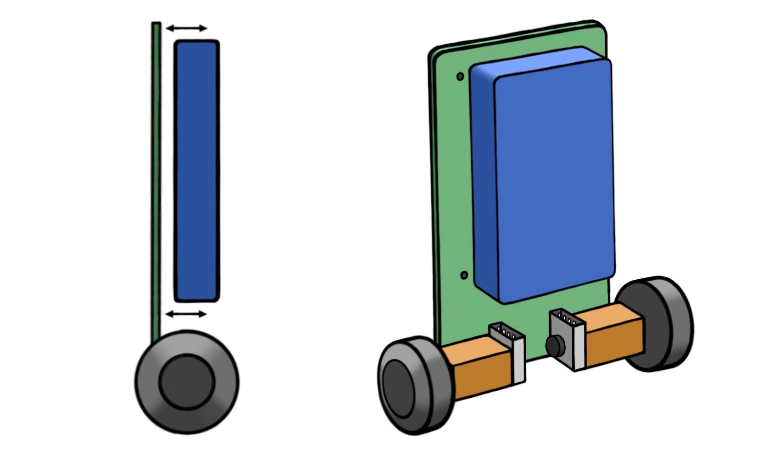
- Form. If we’re sticking with the classic self-balancing robot challenge, we’ll need two motorised wheels, one on each side of a frame — easy. We’ll make its body taller than it is wide, so it doesn’t naturally balance. Now that would just be cheating!
- Style. Let’s make this a small, cute balancing robot, roughly the size of a human hand. What would make it even cuter? A little LED emoji face, of course! And while we’re at it, we’ll give it a speaker so it can chirp at us.
- Function. If we’re going to take the time to make our own robot, we might as well give it a few extra functions on top of the basics. Let’s give it a camera and a microphone, so we can play around with autonomy later. And, just to be different, we’ll give it a pair of servo-powered forks, so it can pick up itty bitty things and carry them while balancing. What could go possibly wrong?
Once you’ve chosen your features, it wouldn’t hurt to do a couple of sketches to visualise what you’re creating. It’s easier to work towards the end goal when you can actually see what you’re aiming for. Plus it helps you think about part positioning
Finding the right components
With the concept in mind, we can now start speccing and picking our components. The basic bits we’ll need are a microcontroller (for low-level control of the balancing), a single-board computer (for the camera, microphone, speakers and high-level control), a battery, an inertial measurement unit (to measure the robot’s angle) and, of course, motors. There will also be a few standard components we’ll need like voltage regulators, motor drivers, etc, but we’ll get to that later.
As we go through each piece and identify the specific component we want, we should always remember to keep track of the communication protocols and power requirements we need. For example, if we pick an inertial measurement unit (IMU) that communicates with I²C and requires a 3.3V power supply, we need to ensure our microcontroller has I²C capabilities, and that our system provides access to a 3.3V power supply.
Getting specific and narrowing it down
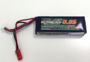
To start with, we’ll decide on a battery to power our little friend. This will likely be the biggest and heaviest component, making it a good starting point for identifying requirements for the rest of the system. Looking for a battery with a good power density (low mass, high capacity), I came across a 2-cell LiPo from HobbyKing which will do the job nicely. It’s the right size, and will give us a constraint for the robot’s minimum width.
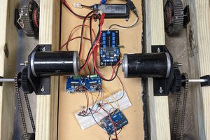
I decided to use stepper motors to drive the wheels, allowing precise control of the wheel speed without needing encoder feedback from a DC motor, or an additional control loop to maintain speed. We’ll use two little 12V geared stepper motors, two stepper driver boards and two step-up voltage converters to raise the battery’s 7.4 volts up to 12V.
The Pi Cam seems like a natural choice of camera, and we’ll pick up a little speaker, amplifier and an I²S MEMS microphone. For the face, we’ll use an 8×8 DotStar Matrix, and to power the forks, an SG90 servo. Lastly, we’ll go with an MPU6050 6-axis inertial measurement unit to track our robot’s orientation.
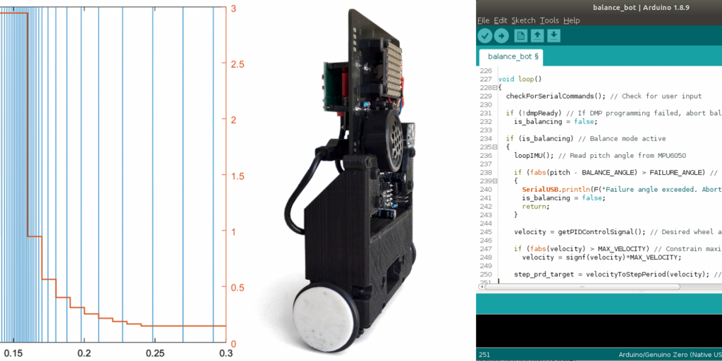
For the sake of keeping everything small (and cute), we’ll go with the Nerdonic Exen Mini for our microcontroller — a coin-sized, Arduino compatible board with a Cortex M0+ CPU. It will talk to the motor drivers, the IMU and our single-board computer, for which we’ll use a Raspberry Pi Zero W. With such a big community around the Raspberry Pi, we’ll have a solid base to work from. Plus it’s a very compact computer that we can connect to wirelessly with WiFi and Bluetooth. We’ll also need a 5V voltage regulator to give us a consistent...
Read more »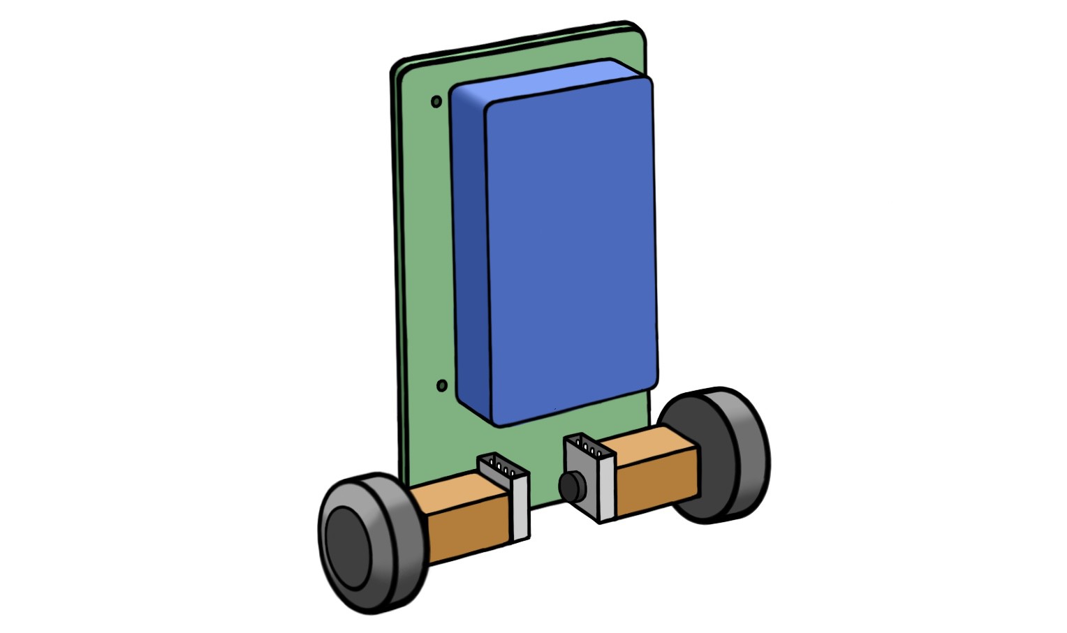
 David
David
 Peter Wasilewski