 Zach Baldwin
There are a few stages to the overall project:
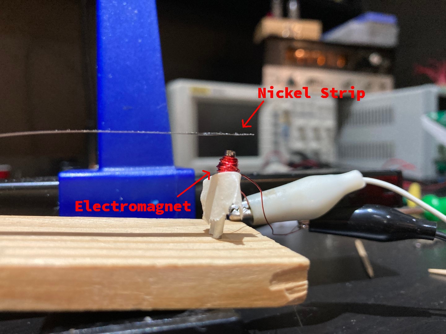
Stage 1: Build the Mirror System (MEMS Mirror Part) - In Progress
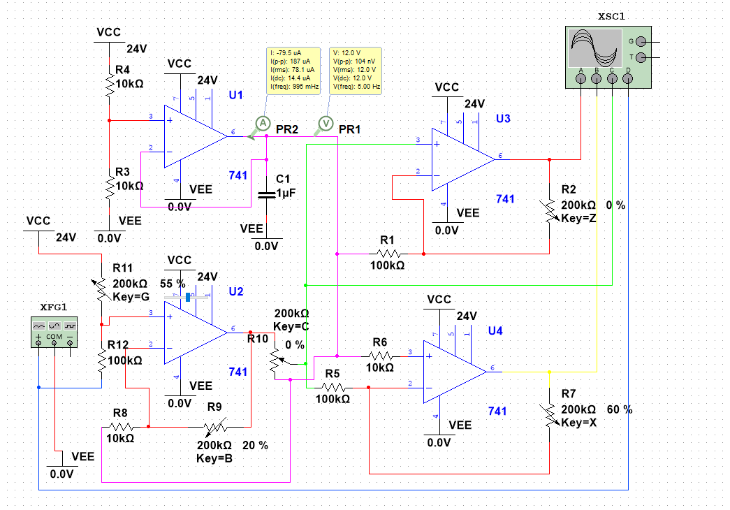
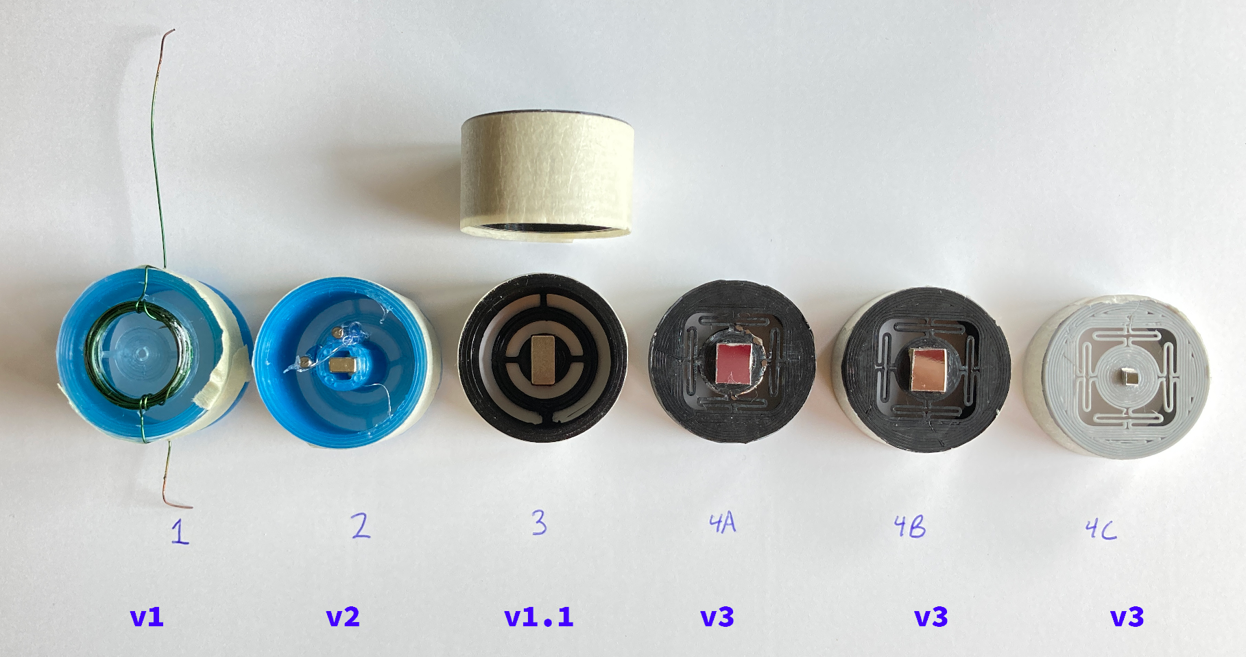
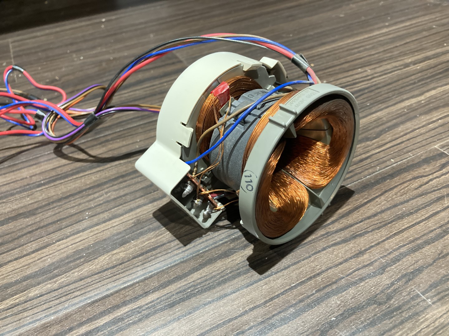
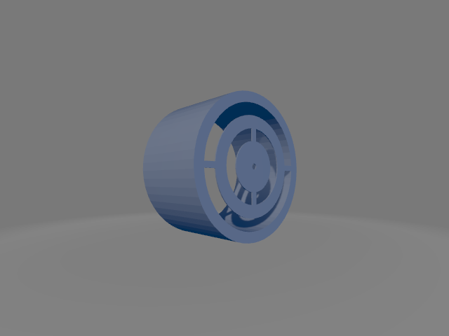
This entails creating a mirror device that can deflect a laser beam with a relatively high scan rate with some degree of repeatability and accuracy. Parts needed for this are the mirror itself, the gimbal, the system for deflecting the gimbal, and a driver for the gimbal deflection.
Stage 2: Add a Screen (Creating a CRT-like display)
The second stage will make use of the mirror gimbal system developed in stage 1 to create a CRT-like display. Ideally, the system will be able to display vector graphics (like those in Asteroids Deluxe). Currently, the plan is to use a UV laser to excite some form of phosphorescent screen to give the system a glow reminiscent of a CRT.
Stage 3: Video Input (Tentative)
If the display is performing well and appears to be capable of performing raster scanning, I may try to implement some form of composite or VGA video decoding/input. This may take the form of keeping up with the incoming video signal and displaying it as it comes in or potentially grabbing a single frame every few seconds and using a long-persistence phosphor to allow the system to slowly raster out each frame.

 Lucy Fauth
 Arno
Arno
 jayframe
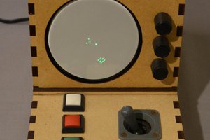
 Mark Atherton