 alberto nunez
-
1Software:
Right after power on, Rpi Pico puts a low level on the GPIO that is wired to the power circuit to keep it powered, then decides which file should be played, and after the sound finishes, a high level is put on the GPIO powering off the Pico. Additionally a light sensor is read to not play sound when is dark (night).
Sound files are played sequentially, one by one on each power on. A pointer to the next file is stored in nonvolatile memory, be carefully modifying the program to keep writing at a minimum.
-
2PECULIARITIES OF THE SDK C/C++ VERSION:
Sounds to be played must be converted first to WAV format 16 bit mono @ 44100 Hz, then converted to C arrays[] before compiling. The application uses a PWM via digital output and interrupts to play sounds.
The program execution starts almost immediately after power on. The main disadvantage of the application for now, it only supports .WAV files which are big, and cannot be changed without recompiling code
-
3PECULIARITIES OF THE CIRCUITPYTHON VERSION:
Sounds to be played must be converted to MP3 mono format, The app uses audiomp3 and audiopwmio modules to output audio out of a digital pin (PWM). These files are stored in the filesystem provided by CP, so modifying them is straightforward, just drag and drop.
MP3 files can store about 10 more sound time than WAV for the same file size, however CircuitPython runtime execution takes more than a second after power on, so probably it won’t be a good thing for any kind of final application
-
4Hardware:
External components are part of one of the three different functionalities:-
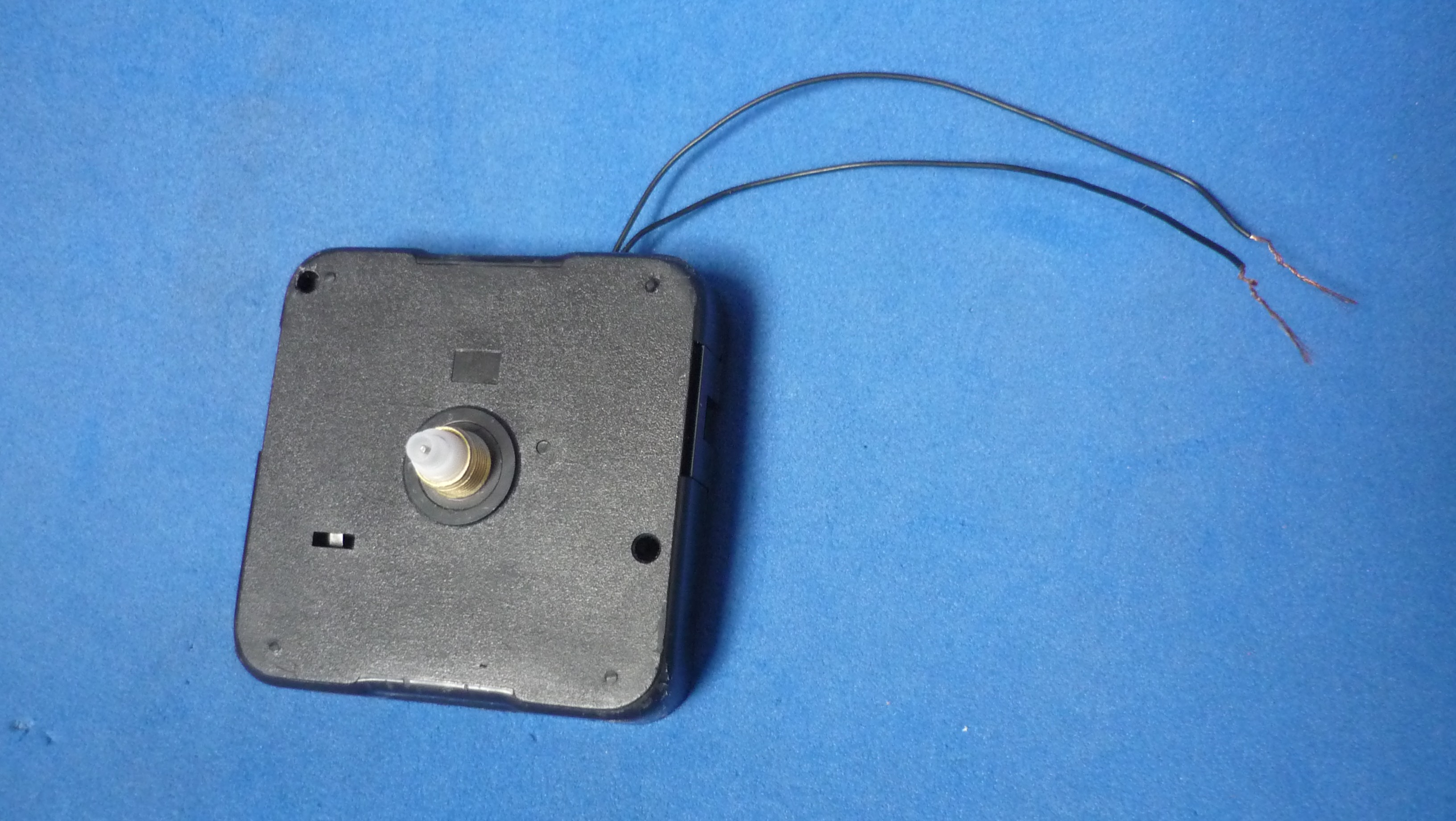
On/Off : The circuit is made up by a MOSFET, Drain terminal connected to 3V3_EN and the Source terminal connected to GND. Connected to the gate are 2 elements: A capacitor to ground, and a resistor to V+. The circuit works in the following way:
-
Step 1: Capacitor is fully charged, turning on the MOSFET and tying 3V3_EN to ground totally powering off Rpi Pico board
-
Step 2: Capacitor is quickly discharged by the brief closure of the contacts of the clock movement, turning off the MOSFET, and powering on the Rpi Pico. The first thing to do after power up, is keeping the capacitor discharged with the aid of a GPIO output in low level.
-
Step 3: While sound is played, low level on the GPIO is kept. Once sound finishes, GPIO output turned high level, so MOSFET turns on again, powering off the Rpi Pico until the next switch closure
-
-
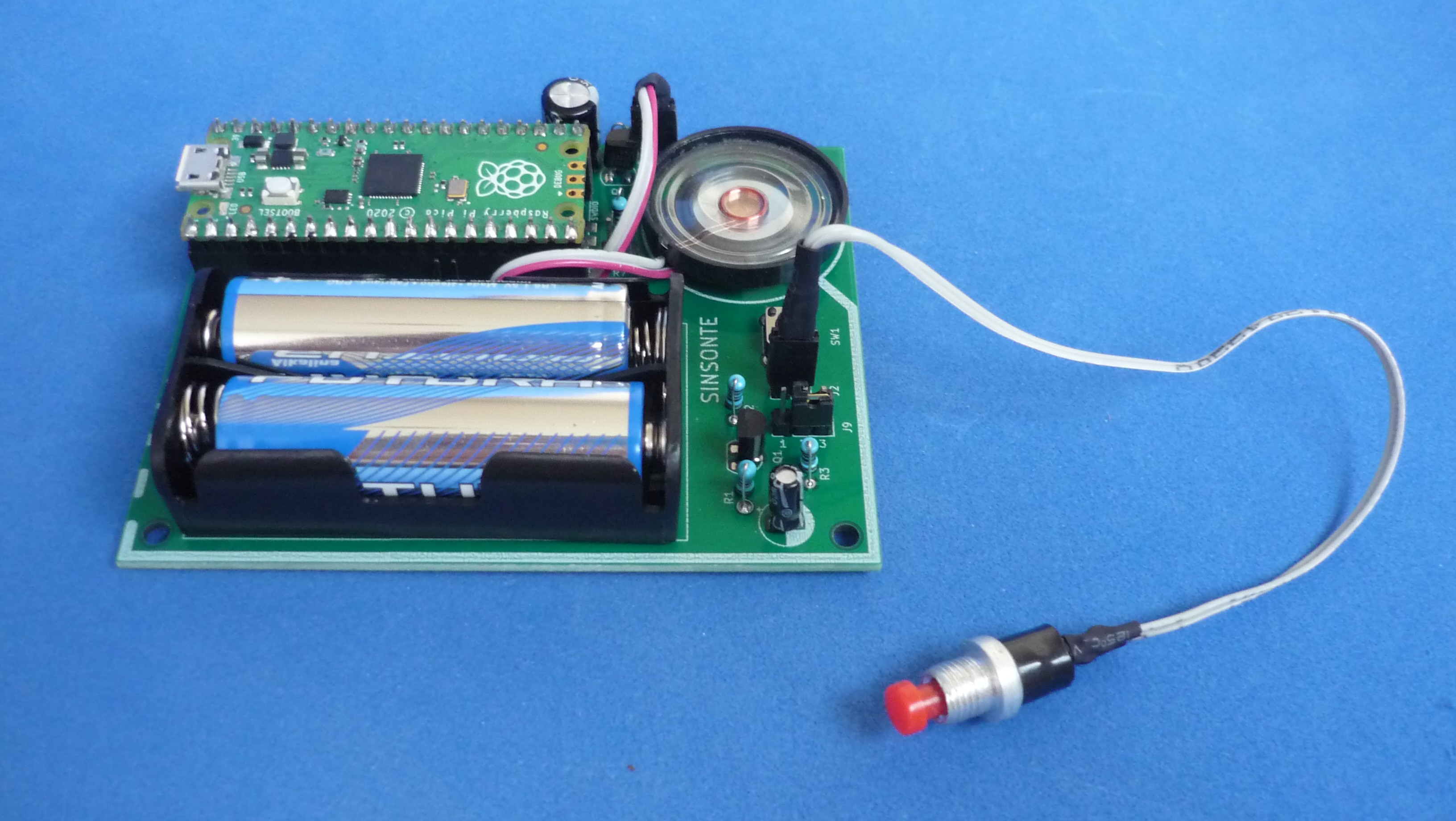
Audio amplifier: Single-stage, single NPN transistor powers a small 8 Ohm speaker. There is also an input RC low pass filter to smooth noise due to the PWM output.
-
Day/night detection: Visible light sensor to avoid playing sounds at night. Connected to an ADC pin
-
-
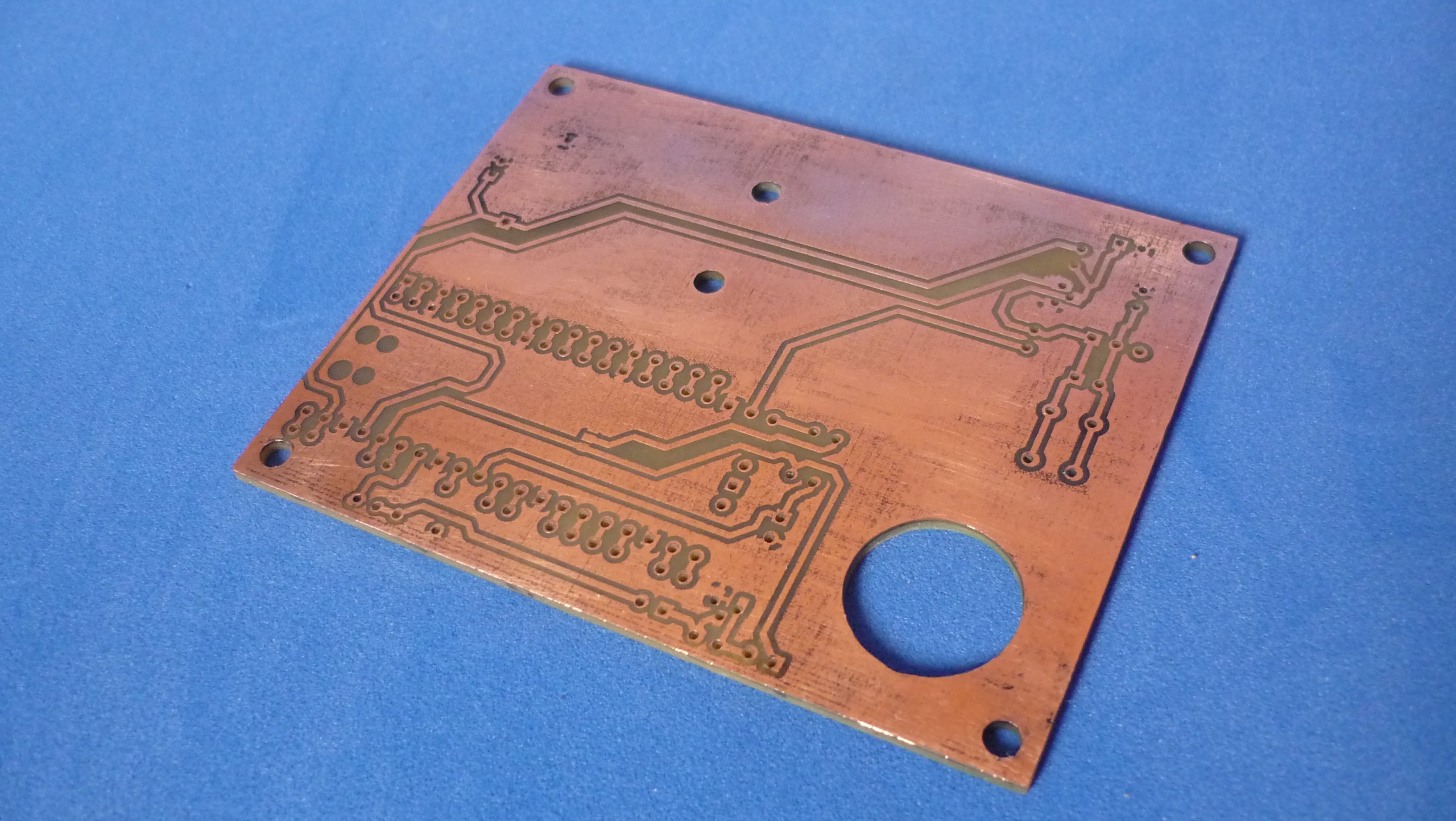
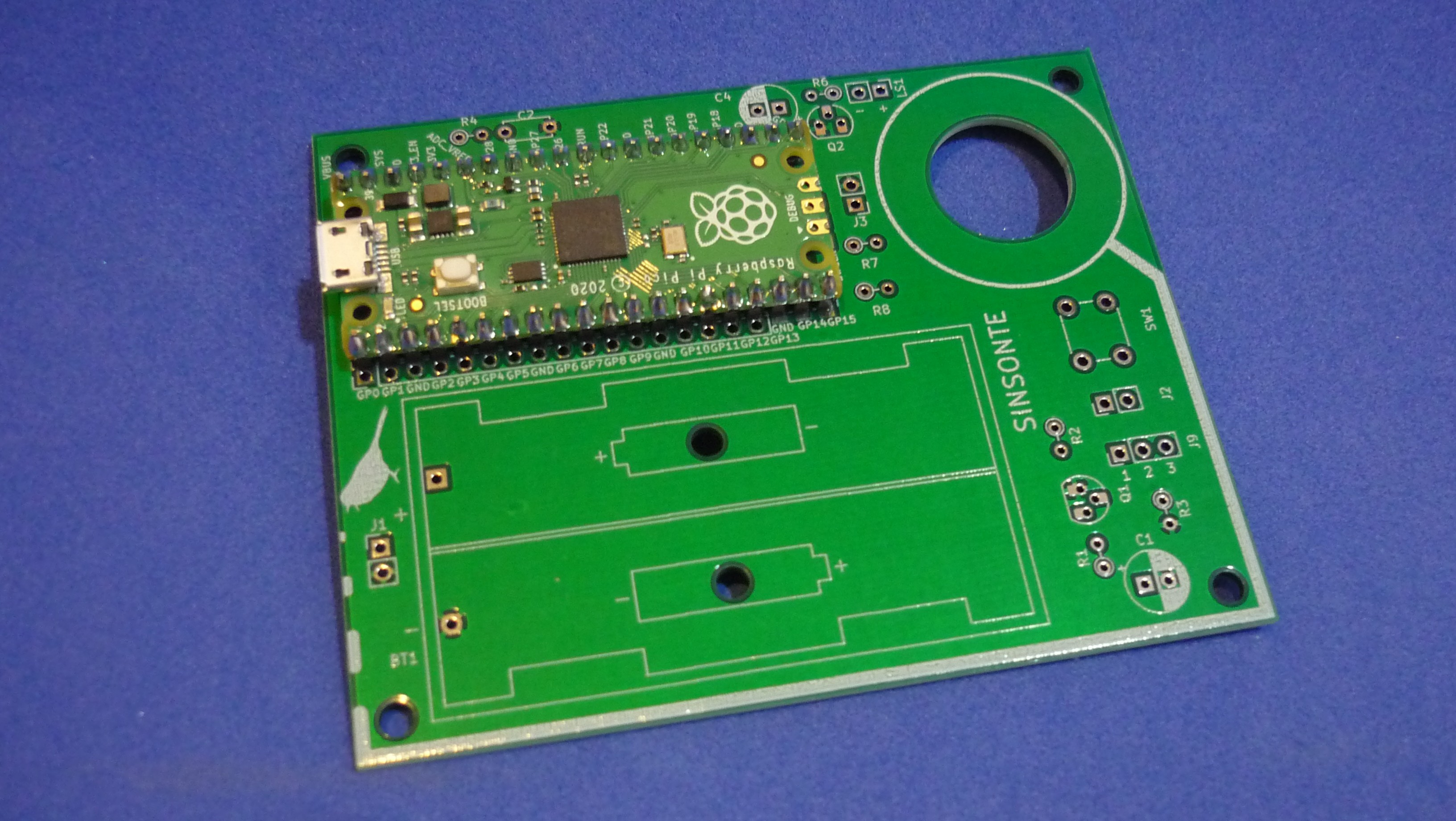
5Board assembly
Rpi Pico, speaker, light sensor, and clock contacts could be soldered directly to the PCB to get a very small height profile, or add pin headers and female sockets for a more flexible option.
The single sided board can be etched at home. There are some free gpio pads for experimentation and also mounting holes near the corners
![]()
![]()
![]()
To build the wall clock, choose a plate or disk made of plastic or wood, with enough diameter to hide the clock movement and the sound board. Fix all electronic components and then decorative accessories like LED lights. Finish it with the paint work
![]()
![]()
![]()
![]()
For hour adjustment, remove all batteries and clock hands (hour, minute, second). Slowly turn clock adjustment knob until a “click” sound is heard. Put all clock hands pointing to 12 O’clock. Put the batteries. Sounds can be shifted pressing the momentary push button switch on the board.
-
6Bill of materials
- Female header 2.54mm shop now
- Male pin header 2.54mm shop now
- 1/4W 1% TH Resistors shop now
- Push button 6x6mm shop now
- Raspberry Pi Pico shop now
- 2xAA battery holder for PCB shop now
- 8 Ohm speaker 29 mm 0.25W shop now
- NPN BIPOLAR TRANSISTOR 2N2222A shop now
- TH Radial Electrolytic Capacitor shop now
- TH Ceramic Disc Capacitor shop now
- Quartz clock movement with trigger shop now
- Wall Clock hooks DIY shop now
- TEPT5700 visible light photodiode shop now
- | LED Copper Wire with battery box shop now
-
7Circuit board
- Sound board (hardware directory) SINSONTE
-
8Software
- Firmware CircuitPython & SDK C/C++ (software folder) SINSONTE
-
9Optional components:
- 3 pc step drill bit 3-20 mm + centerpunch shop now
Halloween talking clock based on Rpi Pico
Halloween talking clock that plays sounds every O’clock hour. Only a few external components (easy to source and solder) needed.
Discussions
Become a Hackaday.io Member
Create an account to leave a comment. Already have an account? Log In.