-
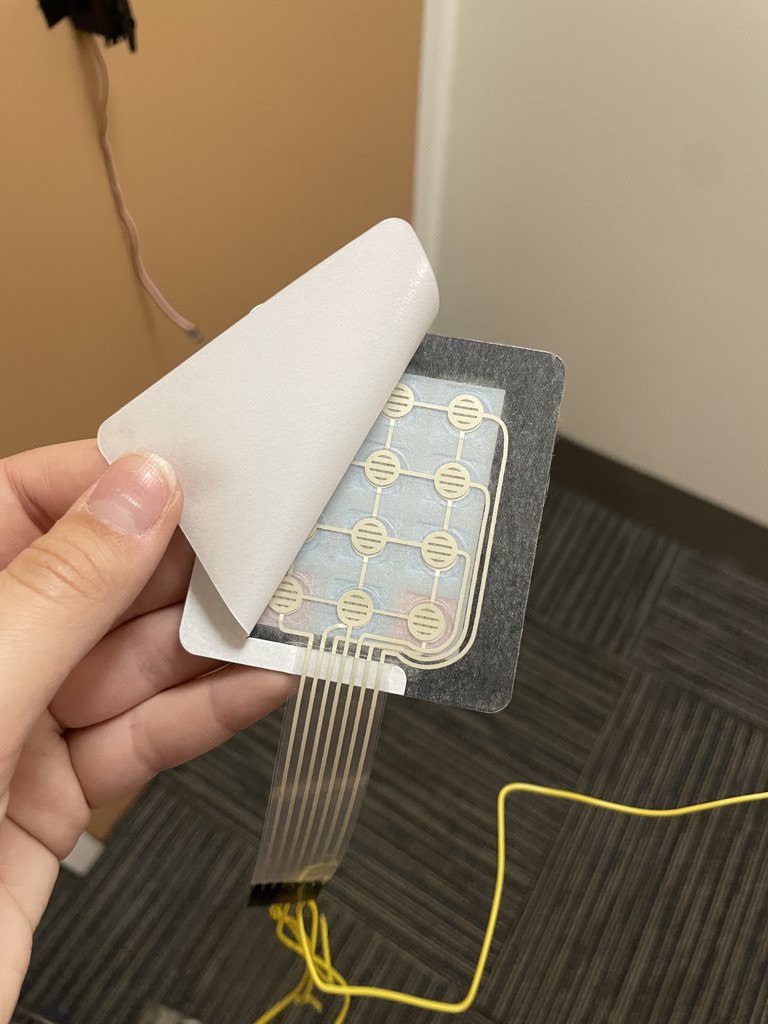
1Mount keypad
- Peel back the paper covering the adhesive and press it on the outside of the door 6 inches above the lock.
- Maintain light pressure for 30 seconds to ensure it remains attached
![]()
![]()
-
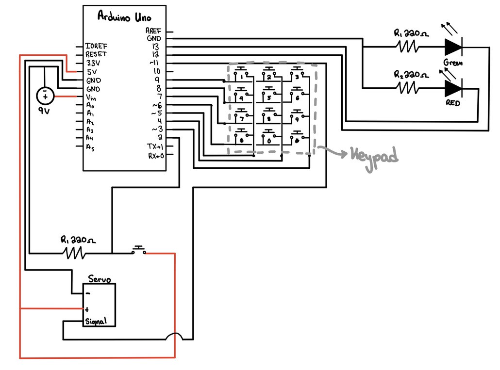
2Build the Circuit
- Use the circuit diagram:
![]()
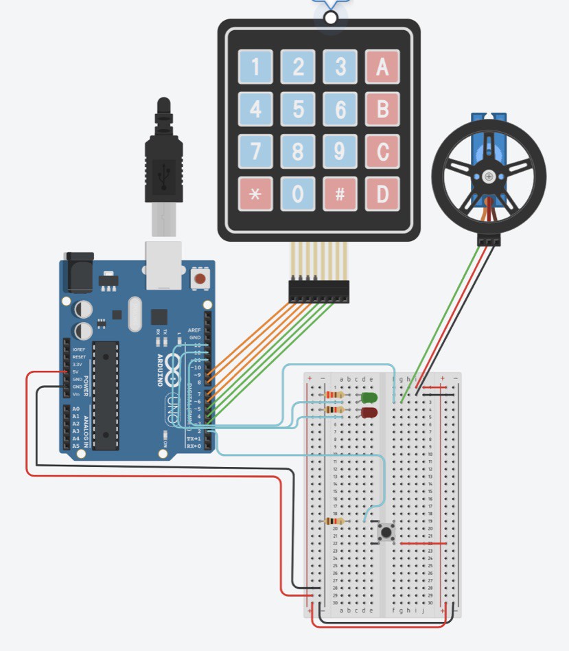
- Or the tinkerCAD: https://www.tinkercad.com/things/crqJkqZNKce
![]()
- This diagram shows what will be on the inside and outside of the door:
![]()
-
3Tape Wires
- Tape the wires that wrap from the outside of the door to the inside of the door to make sure that the door will close easily and prevent any wires from coming undone
![]()
-
4Add the breadboard
- Tape the breadboard to the outside of the door immediately below the keypad using gorilla tape.
- Make sure to leave 2 inches between the edge of the door and the breadboard to allow the door to close properly.
![]()
- The front of the door should look roughly like this now.
![]()
-
5Add the Arduino and Battery
- Tape the Arduino to the inside of the door at the same height as the breadboard on the opposite side of the door.
- Tape the 9V battery on the inside of the door 3 inches to the right of the Arduino
![]()
-
6Add the Door Lock Fitting and Servo
- Tie a 1 ft. and 3 in. of string to the 3D printed door lock fitting and slide it over the door lock
- Tie the other side of the string to the Servo hook.
- Make sure that when the door is in the locked position, there is enough string length for the servo to be about a foot to the right of the door lock
![]()
- Use the string to ensure that the servo is level with door lock fitting. This will minimize the amount of torque the servo needs to output in order for it to be able to pull the lock open.
- The back of the door should look like this when locked:
![]()
-
7Upload Code
- Upload the Design Project Code to the Arduino using the USB to USB B cable and the AutoUnlocker is now ready to use.
-
8User Instructions
These instructions outline how to use the door unlocker once it has been built.
- Begin on the outside of the locked door
- Press the button located on the breadboard once. This will let the AutoUnlocker know that you are ready to start entering the password.
- Then you can enter the password by pressing the correct buttons on the keypad.
- Once you have finished entering the password, press the # key.
- This lets the AutoUnlocker know that you are done entering the password
- So for example of the password is 2023, you would press the button and then enter 2023#
- If the computer is connected to the Arduino with the USB A to B cable, the serial monitor will print whether or not your password is correct. It will also show you all of the keys that you pressed excluding the # key
- If the password is correct, the green LED will blink three times and the servo will rotate to unlock the door
- If the password that was entered is incorrect, the red LED will light up for three seconds.
- You are free to repeat the process again after a failed attempt. Begin again by following these instructions starting at step one
- You can change the passcode by editing the code.
- The only line that needs to be changed is:
const String password = "1234"; // this is where you can change the password if you want to!
- You can create a new password by changing the numbers within the quotation marks
- For example if I wanted the password to be 579402048284901948, my new line of code would be:
const String password = "579402048284901948"; // this is where you can change the password if you want to!
- Then the revised version of the code must be uploaded to the Arduino by connecting your computer to the Arduino using the USB A to B cable and pressing upload


Discussions
Become a Hackaday.io Member
Create an account to leave a comment. Already have an account? Log In.