I found this video which shows how the slider would ideally perform, just that you can press down on it and it can be set to allow movement "infinitely" in either direction.
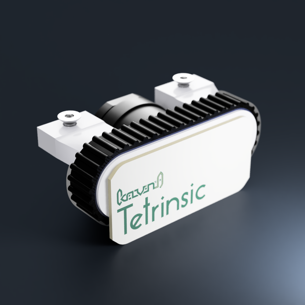
Tetrinsic is the merge of the above motorized sliding potentiometer and the SmartKnob View:
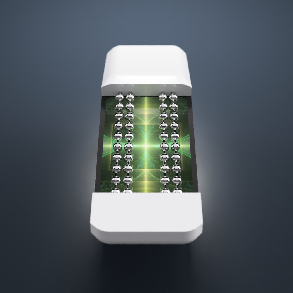
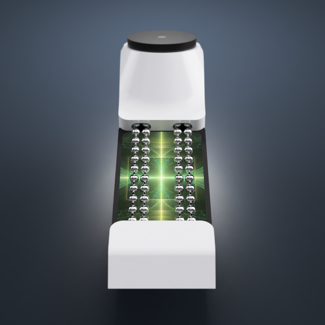
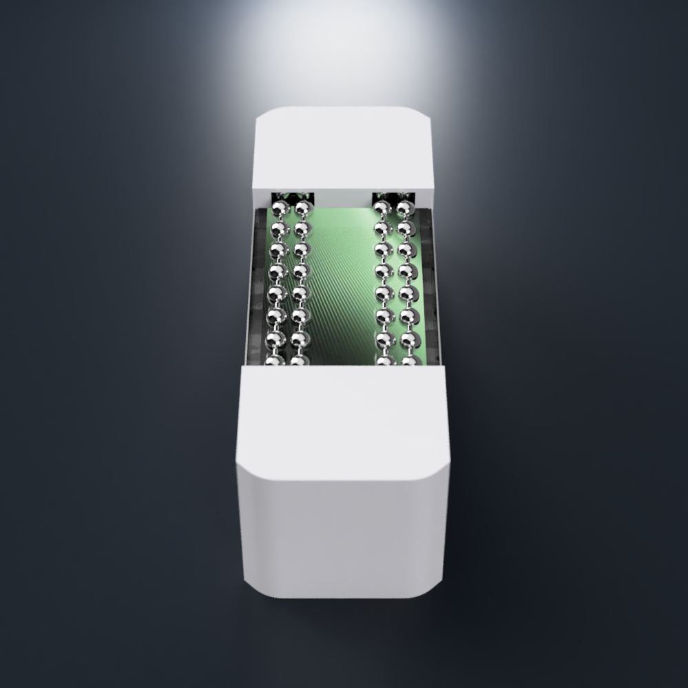
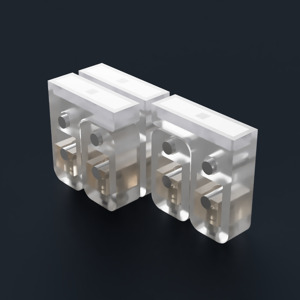
The visible area is designed to be as minimalist as possible, so that things like an LCD backlight can be used for designs:
The cool thing about Tetrinsic is that you don't have to remove a magnetic top layer (as seen in Flux) or hotswap out the switches (on a more traditional keyboard) if you want to change tactility. Just tune it to your precise tastes in software.
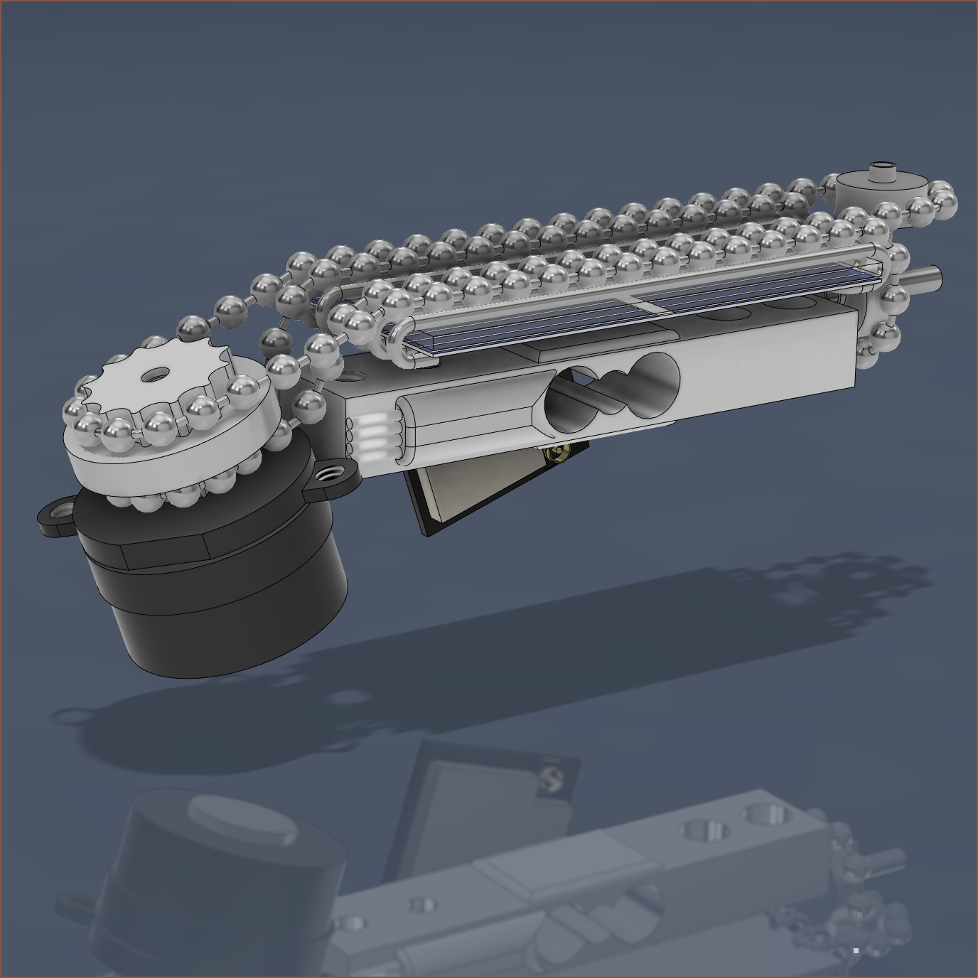
Unfortunately, Concept3.2 had a turning radius that was too ambitious. Thus, on August 10th 2023, it was decided that a redesigned Tetrinsic with dual motors and the ability to weave the Thumb Tetrinsic around the FingerN Tetrinsics would be the best strategy forward. This also allowed anything to be placed inside through the loop.
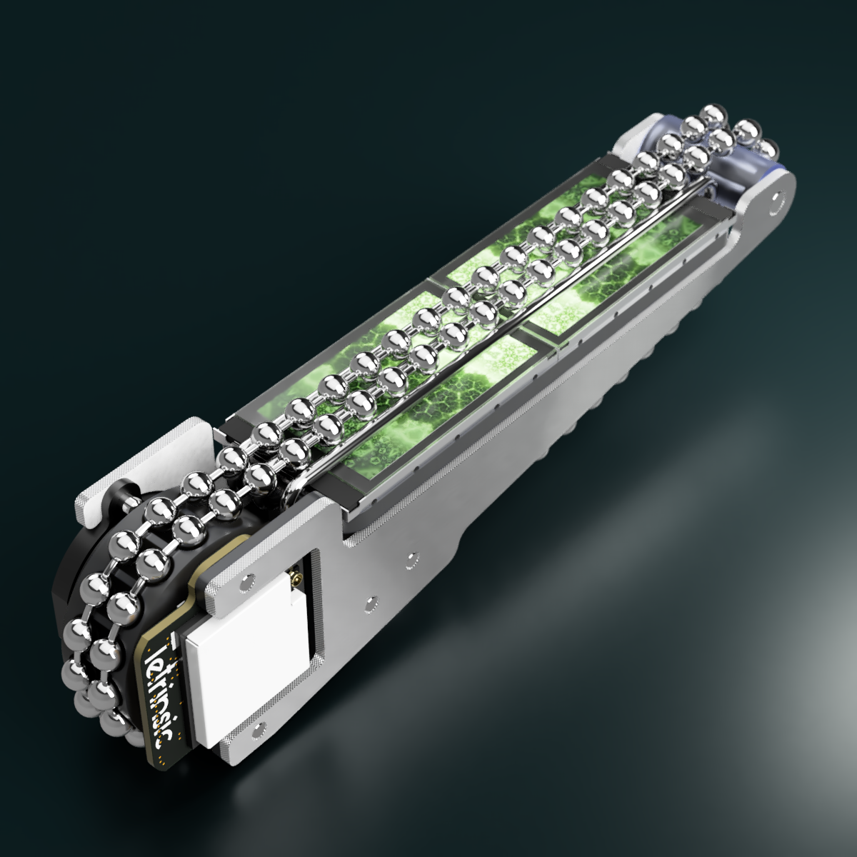
From Aug 25th, the focus has been on designing for #Tetrescent [gd0150], where a solar cell is placed inside said loop.
After creating the new Tetrinsic PCB that uses the ESP32-S3-MINI-1U, on June 30th 2023 I eventually decided to increase the size of the ball chain to 3.2mm, make it so that there is only one path that is exposed and, to increase the usable length : body ratio, doubled the screens. This is the first concept CAD model that was electromechanically complete, made on July 18th 2023.
Tetrinsic Gen 2X2 (smooth top wedge shape)
Development started on Jan 12 2023 and moves the components so that the load cell is parallel with the LCD and that the motor does not protrude the top surface. The aesthetic is further improved whilst improving the ability to slide into a pocket (for TimerSpy). This was first called Tetrinsic Concept4.
I then spent subsequent weeks turning this concept into a more fully-designed prototype, and added a photovoltaic solar cell variant. This concept was using 2.4mm ball-chain that slid on 1mm diameter stainless steel tubes. The above is more-or-less as far as I got before I started work on the PCB. Unfortunately, the design got a bit too large such that I couldn't come up with a solution for #Tetent TimerSpy [gd0136].
Tetrinsic Gen 3X1 (wedge shape)
The shape is to allow Tetrinsic to be mouned on the back of my hands and slide into pockets for TimerSpy and fit into the square prism shape of TestCut. A notable improvement is that an off-the-shelf load cell can be used, saving on build time, increasing precision and reducing displacement.
Development started from Jan 4 2023.
Tetrinsic 2.0 (LCD backlit, dual 2mm ball chain)
Tetrinsic 2.0 is an internal name to refer to the redesigned version I started developing from Dec 26 2022. It's not actually the second version of Tetrinsic, since I haven't actually made a first one yet. Think of it as Tetrinsic 2.0mm.
This redesign should bring advantages such as lower sliding resistance, shorter allowable finger offset distance, shorter height, a full-bridge-configuration pressure sensor instead of an iffy half-bridge, a much more popular microcontroller (RP2040 vs M032) (thus, better software support) with more RAM and FLASH memory and, most excitingly, a background display.
I should mention though that you're unlikely to see the tops of the Tetrinsics during use.
Tetrinsic (2GT belt, single BLDC motor)
When I started #Tetent Timespy [gd0136], I came to the realisation that the 5 seperate buttons per finger row solution I was trying to obtain was suboptimal.
On Sep 14 2022, I changed the design to center around a mini BLDC motor connected to a 2GT belt that also acts as the keycap surface. This was inspired by various open source projects (namely the SmartKnob View) and uses the motor and force sensors to simulate different sliders and tactility, as well as make the weight and amount of actuation points software adjustable.
The motor is also used to reduce the learning curve as much as practically possible, as my main question I thought of when learning to touch-type was "Where is the key? What finger do I use to press it?"
Tetwin (double-action switches)
Finding out about hall effect switches and their potential double-action feature, I started researching double-action switches.
Small tactile switches (0.6N, 1.6N) do exist, but from pressing my camera's shutter button, their second actuation force is too high for all but the thumb. I discovered Riskable's Void switches and how the design could allow for adjustable actuation force without the need for an electrical connection to the keyboard PCB. Magnets seemed to be quite cheaper than buying 0.8N and 0.5N tactile switches, and allows for LED backlighting because the components needed are smaller.
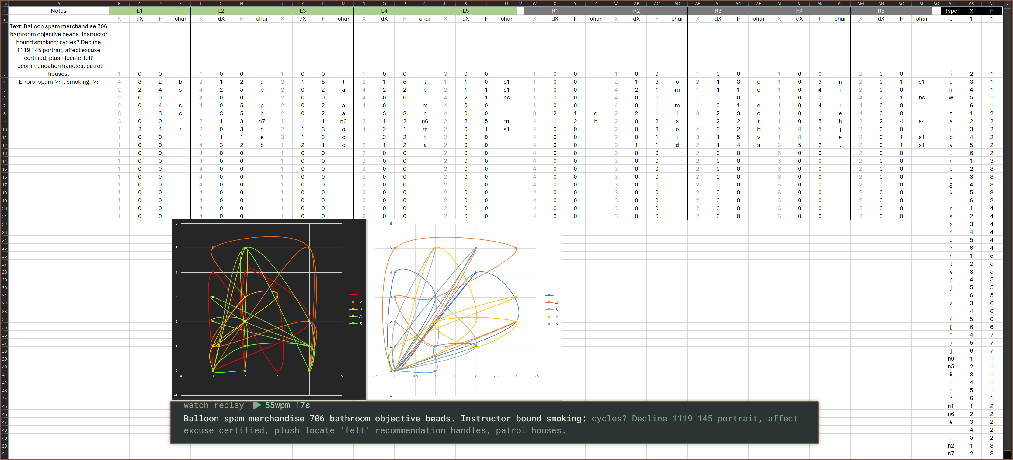
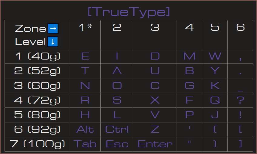
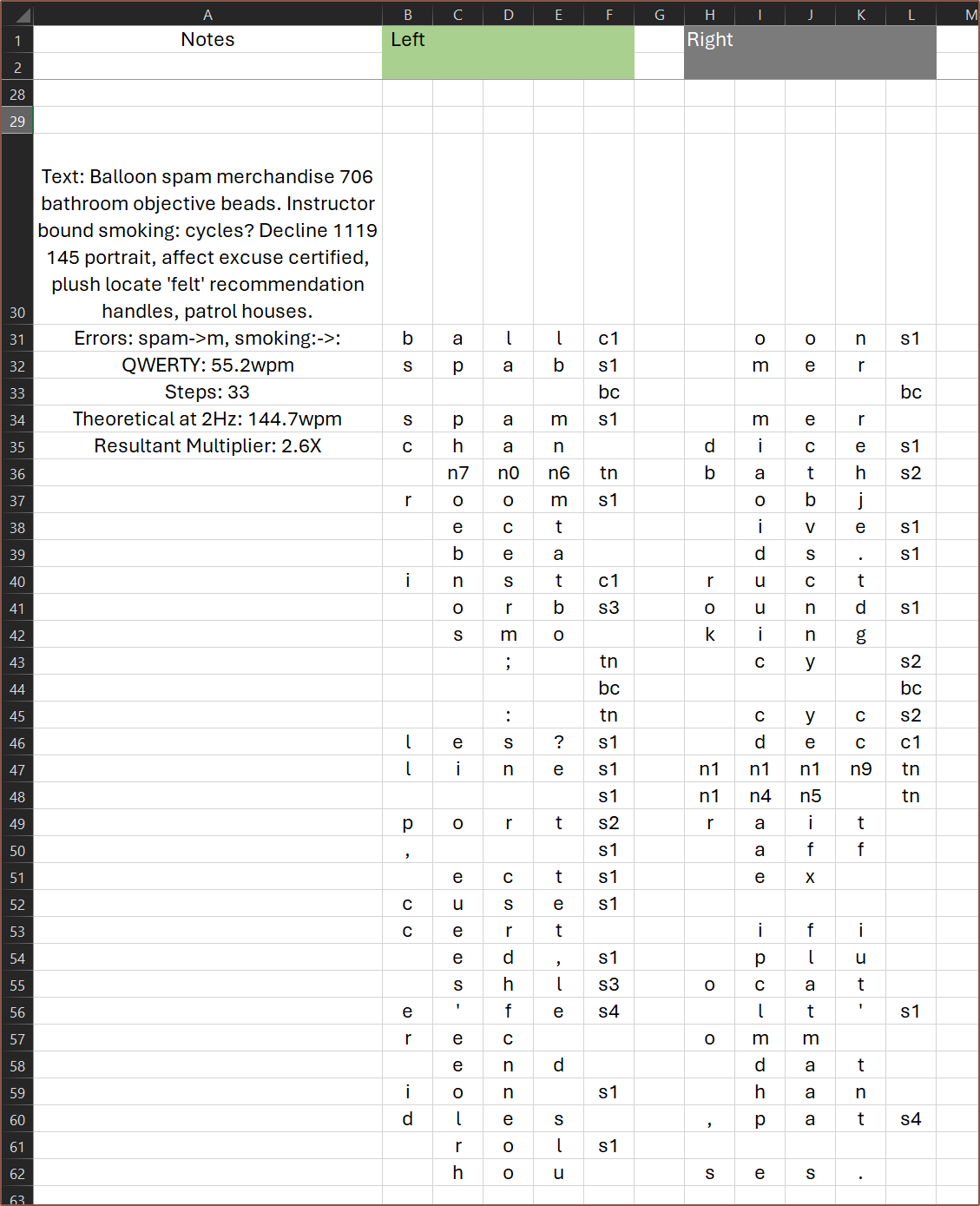
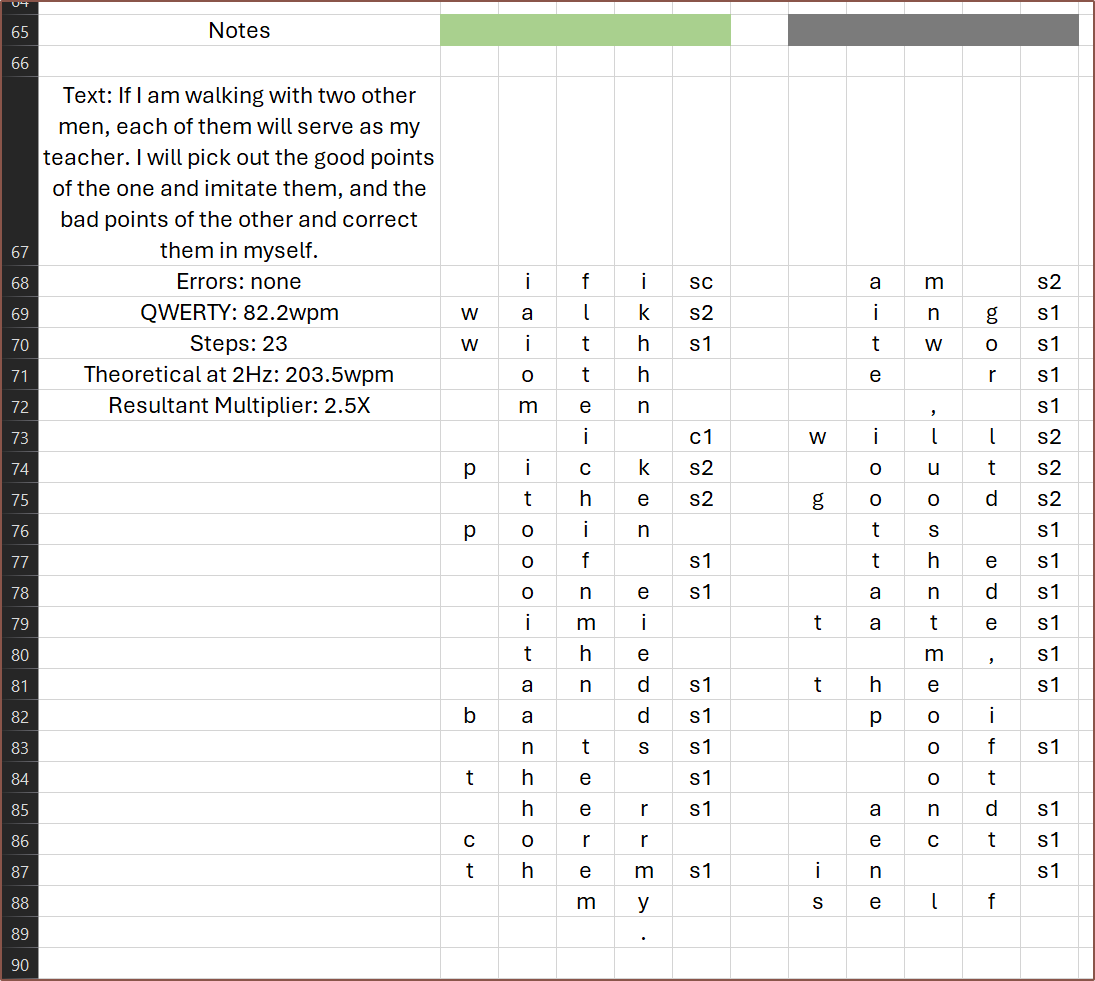
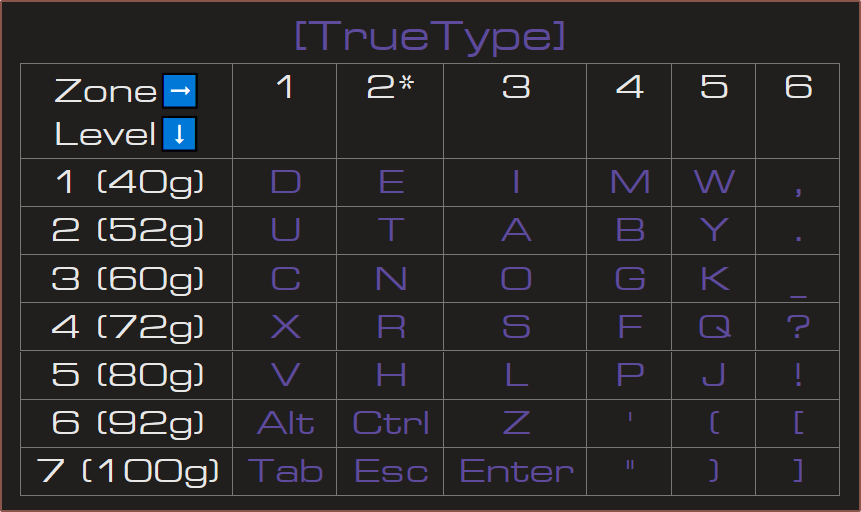
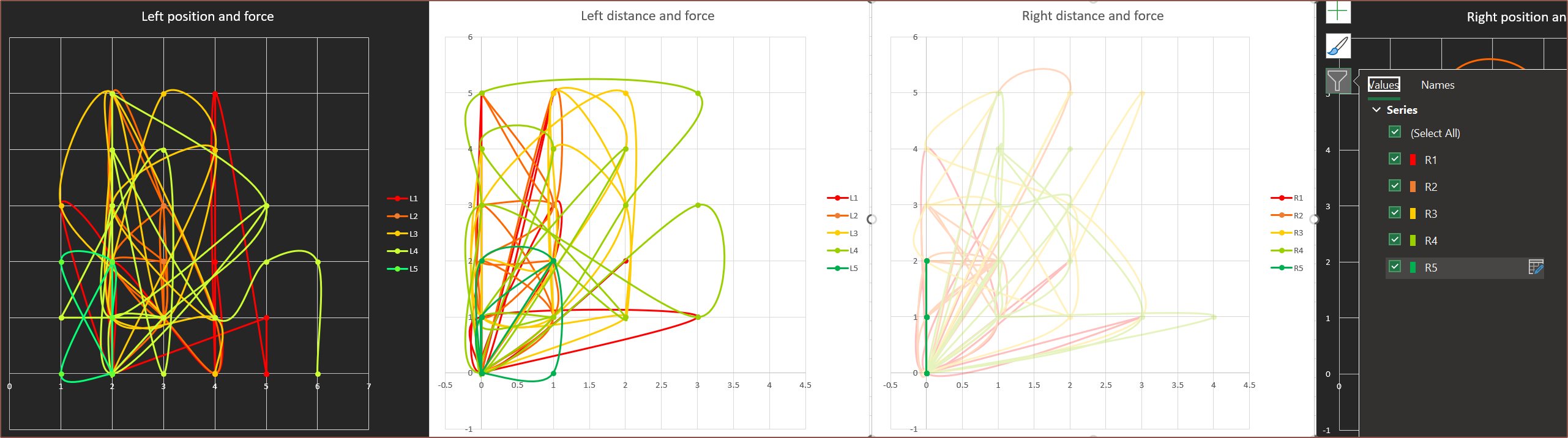
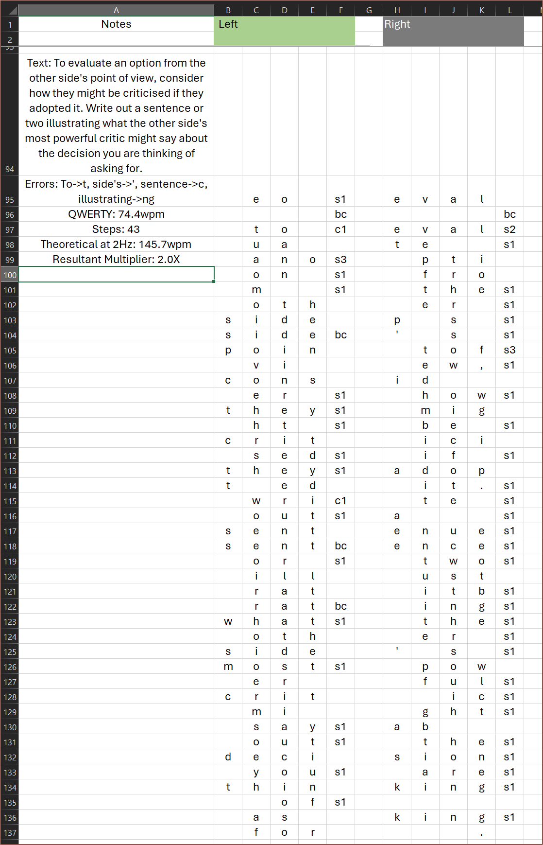
So I spent maybe 2 hours setting up the groundwork of this excel spreadsheet and then maybe 15 minutes actually puttinging in some values. This spreadsheet assumes I'm using #Tetrescent [gd0150] and in a mirrored (aka vertical) mode where for both sides, the placement of characters is Finger1->Finger4.
I've tried plotting the position and force level in the black chart, and the change in position and force level in the white chart. For the most part, I can't really gather any insights so far. Perhaps it's just because I've only input the first sentence to see if I should continue or not.
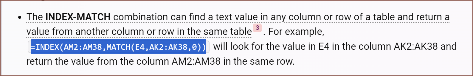
The fanciest part of the spreadsheet is the use of a lookup table, but the command LOOKUP didn't work. The good news is that we now live in the advent of AI:
In this spreadsheet, I assume that a blank field for the char columns means no input, i.e. 0 force from fingers. Thus, my equations are:
For position X: If the char field is blank, use the previous position
(I'm just lifting my fingers), else find the corresponding position for the
char:
    =IF(ISBLANK(E4), B3, INDEX($AS$2:$AS$56,MATCH(E4,$AR$2:$AR$56,0)))

For force F: If the char field is blank, the force is 0, else find the
corresponding force for the char:
    =IF(ISBLANK(E4), 0, INDEX($AT$2:$AT$56,MATCH(E4,$AR$2:$AR$56,0)))
for the fingers, and
For position X: If char is blank and the previous position was 1, go to 2,
else if char is blank, do the same as the fingers.
    =IF(AND(R3=1,ISBLANK((U4))), 2,
    IF(ISBLANK(U4), R3, INDEX($AS$57:$AS$70,MATCH(U4,$AR$57:$AR$70,0))))

For force F: (similar thing to the position calc and finger force calc:
    =IF(AND(R3=1,ISBLANK((U4))), 2,
    IF(ISBLANK(U4), 0, INDEX($AT$57:$AT$70,MATCH(U4,$AR$57:$AR$70,0))))
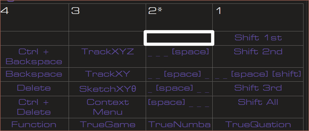
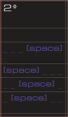
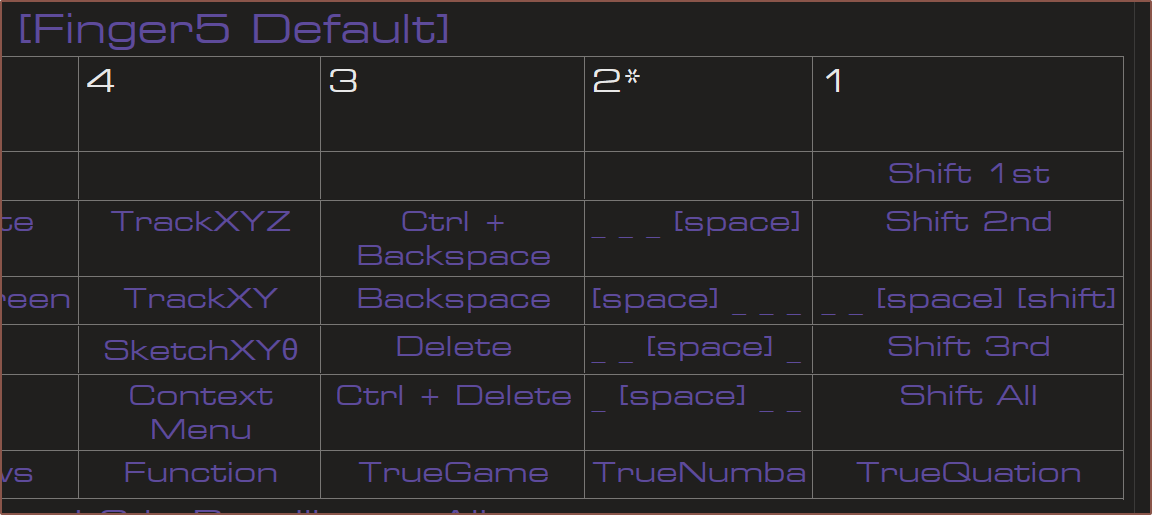
for the dynamic spacebar thing (which could be the Thumb or Finger5). This is because the finger (in this case, Finger5) rests in the below white box of the layout:
The user pulls back to column 1 -- similar to a trigger or that sliding, on-off toggle thing on the PSP -- and then the motor exerts a force to push the finger back to column 2. This allows me to have a virtual button without having to push down on the Tetrinsic. It's similar to how I envision the datahand-inspired layout to function.
Now, the reason why I typed the phrase out first is so that I could also get pseudorandom typos integrated into it. For this monkeytype test, I had 2 errors. The first one has been recreated here, taking the Tetrinsic layout into account:
The code "s1" stands for the first space option, and "bc" stands for "CTRL+Backspace".This typo simulates accidentally pushing too hard on Finger4.
[24 Dec: 20:00]
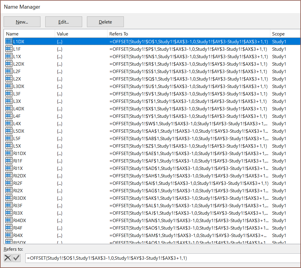
So I've spent a while learning things like the =OFFSET command, so that I could have a dynamic start-end point for the charts without having to laboriously edit tens of values. BingChat initially generated code for =INDIRECT, but then I started moving colums around to make the spreadsheet more readable and the positions didn't update in the charts.
This is the first time I'm even realising there's a "Formulas" tab in Excel, let alone that you can name selections just like in Fusion360.
I've moved things around so that everything is a lot more readable. Hopefully, this gives those finding out about this project a better understanding on how the typing system works.
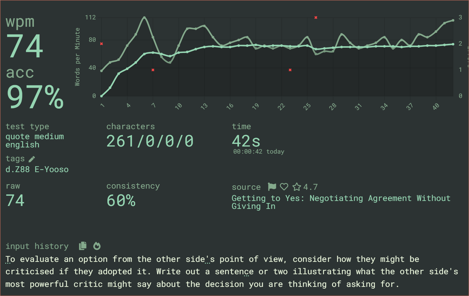
Then I needed another run. I decided to go with a quote this time, and despite it being 5am without having slept yet, I managed to 100-accuracy it.
For both of these, I've assumed I'm proficient enough to realise when I can reduce finger travel, such as being able to keep Finger2 on "O" between rows 76 - 78.
From doing this, I was able to make some slight optimisations to the layout, which can be seen below:
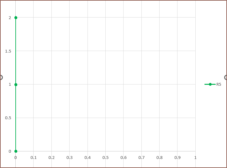
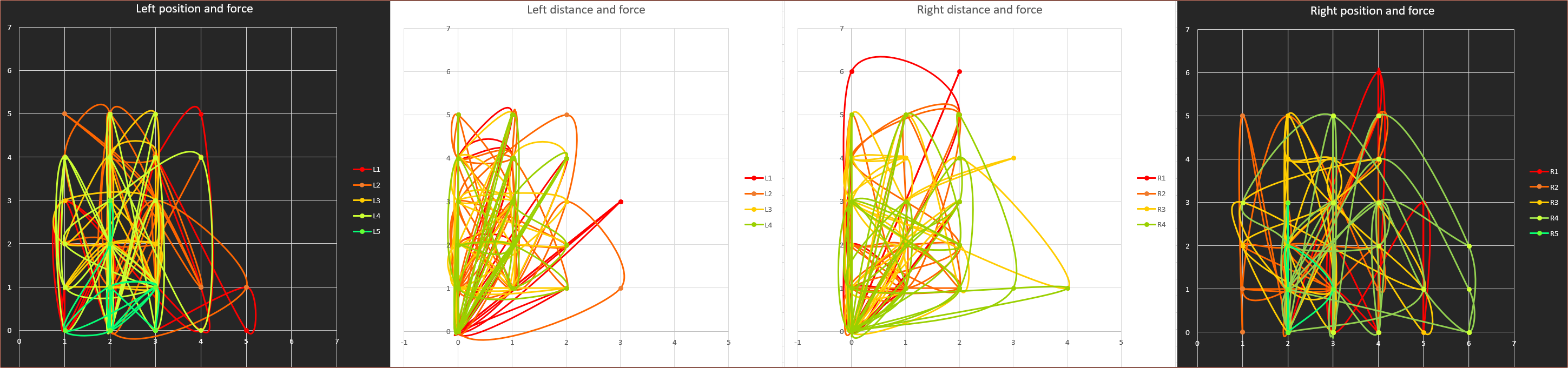
It's still kind of tough to gather many insights from the charts, but at least it shows what I'm interested in for this study. The ideal layout solution is one where the distance-force chart is as close to what Right Finger5 currently is:
As you can see, there is no movement of the finger and only 2 force levels were needed to input the quote. Perhaps that's actually the strat to understanding the data: looking at individual fingers instead of all of them at once.Finger2 is looking very promising, especially the right finger where most of the action is in the lower left corner. In contrast, Fingers 3 and 4 are looking less optimal, with 4 slightly worse overall:My hypothesis is that 4 usually has to deal with punctuation.
[21:30] I've done the next quote, which was a bit longer:
This is how it chords out:
Note that ctrl+backspace applies before the characters denoted by the fingers. It would be rather useless if it didn't work like that, erasing the chord that was enetered at the same time.
As I was doing the chording, characters 'Y' and 'W' stuck out, as well as the fact that 'X' is in a prime real-estate location yet was completely avoided. Since 'W' is only force level 1 as well as being one of the only characters I need to reach on position 5, I left it in place; I thought it'll at least be a nice hop to break up the monotonity or something. I've swapped 'Y' and 'X'. Thanks to that, the distances travelled between steps is mostly constrained to 2 or less. I've also swapped columns 3 and 4 for Finger5 so that there is a lower penalty for backspaces:
Here are the charts:
I found some use of the black charts as a heat-map of sorts.
Another insight I've had from this is that the finger utilisation is comparable, except the thumbs which can be explained; the persona I'm emulating is a user that mainly uses Finger2, 3 and 4, only using Finger1 to fit 4-letter syllables and words into a single chord. I thought Finger5 wouldn't be doing much, but I have been proven wrong.
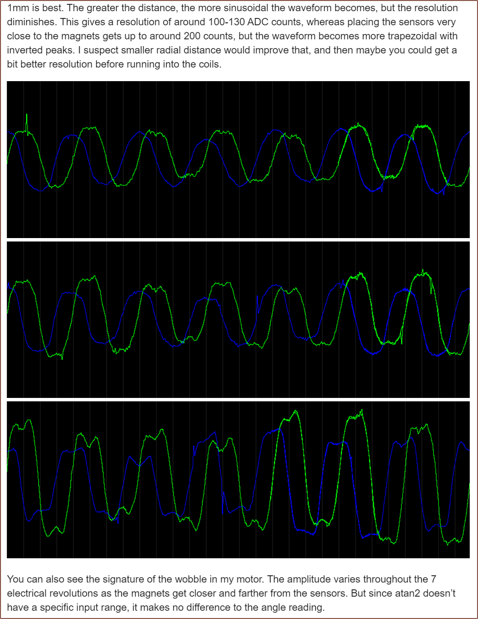
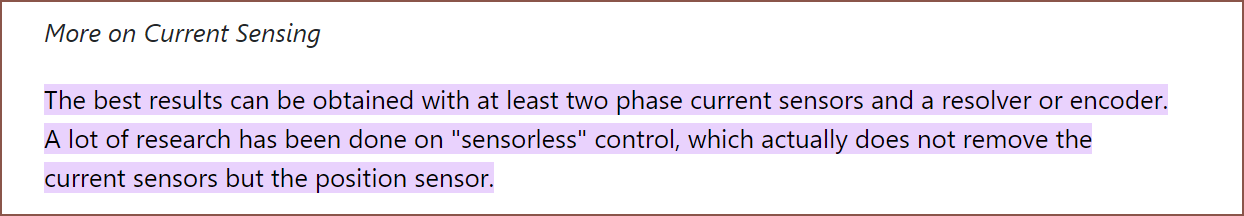
Firstly, I want to mention that @dekutree64 commented in this log from #DIY Mech/Exoskeleton suit. about his experiments on using 2 hall effect sensors in this form thread. The original poster (OP) of the thread mentioned a drawback was a "computational intensive trig operation" but deku responded with a link describing an approximation that is correct to 0.28 degrees. Now, deku's been able to get the below results, with 3.3V circuitry:
Thus, I belive I'm going to go ahead with using 2 linear hall effect sensors for positional tracking.
Waterproofing Tetrinsic?
Secondly, I want to add water resistance to the list of supported features of Tetrinsic.
I've been mulling over going the extra mile to obtain a higher solution coverage. Just as I aprieciated water resistance on full-android smartwatches, I believe water resistance would further open up the applications that Tetrinsic could be used in (for example, writing a novel in a bath or jotting down sudden ideas in the shower), as well as increase resilience against day-to-day life.
The idea is simple, which is to encase the coils and UVC components in a resin transparent to UVC wavelengths if it exists. Something thermally conductive would be ideal.
For the load cell, a solution may be to coat the strain guages in nail varnish or a coating specifically designed for this application.
I was writing this log and then something happened and poof it went, so I have to write it all again. I must embrace the saltiness I feel.
Moving on, I haven't been able to get around to learning how to set up and simulate electromagnetic coils for use in Tetrinsic. I just lack the time (and time security). This entire situation is a cyclic redundancy, as I want to use a Tetrinsic powered input device to research/design/document Tetrinsic.
Conceptually, the plans I've got for #Tetrescent [gd0150] meet or exceed my needs and wants for an input device, but there is one thing that is still missing and is one of the important ones: wearability. #Tetent TimerSpy [gd0136] was when I tried solve this with a wrist or hand mounted solution, but that had its own challenges -- namely that I couldn't easily take my coat on/off and that coming up with a solution where I could enter data with both hands was difficult. Now, it seems that Tetrinsic would be too large for such a solution anyway.
After starting my new Head Mounted Display (HMD) project, #Itinervate [gd0151], I started considering a head-mounted input device to complement it, specifically one where the active area is against the cheeks. The benefits I thought of were:
My hands usually rest on my cheeks when I'm thinking.
Each hand can reach both sides of the cheeks, as well as I can use both hands simultaneously.
I really want to be able to recreate the feeling of working under the speakers of a restaurant/store.
I've paid close attention to the aesthetics of Tetrinsic when implemented into a potential design, which is important for something that would be easily visible.
I'm not going to target for something "discrete" or "unnoticable" because unless it's a pair of glasses or a mask, any item worn on the head is going to be noticed.
This is a roughly-scale sketch of what I was able to create in PowerPoint:
I intend for those diagonal bends to actually be a smooth curve, so the above is more like a low-poly rendition. I'm also expecting the trailing edge to get smaller (kind of like a comet). The grey lines are Tetrinsics that have at least 90mm of stroke length (to make sure that there's enough space for both my fingers and the electromagnetic coils). Since the middle white part curves downwards and becomes shorter than this distance, I've decided to make 2 of the Tetrinsics longer and terminate those at the top of the part that covers the ear. Then there are 2 dark grey lines which represent imitation Tetrinsics (similar to fake speaker grills).
I haven't yet considered how this is all to be mounted to the head as I want it to complement Itinervate, which I haven't yet made a concept for. All I know is that there are going to be 2 screens above natural eye level that come out from the centre.
I've more-or-less have the mental 3D model of the new Tetrinsic concept, but I'm not modelling any of it until I've first set up and simulated some coils. I've got at least 360 of these I need to either create or buy from a manufacturer in China (since the MOQ is likely high enough for one to take the order). I'd like to know the performance of both a foil and wire coil before I continue further.
Ideally, I'd also like to simulate so that I can find the optimal location for the hall-effect sensors.
All this means that I need to find and learn how to use a new simulator, as Fusion 360 doesn't do this.
EMWorks
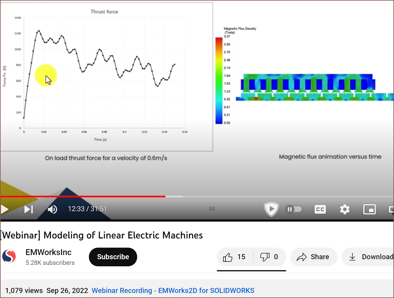
The first thing I found was a webinar on linear motors:
It seems that the force exerted on the mover is what I ultimately want to find out.
The price of this software is "Contact Us" though.
FEMM
Looking into the free options, I found this forum post from 2010 that asked the community to pool together any finds on this kind of software. FEMM was mentioned, and it already looks like the kind of program I'm looking for.
They also seem to have a lot of tutorials. Hopefully, one of those is how to get force data.
Elmer FEM
I then found this resource that is a list of electromagnetic simulators. In addition to coils, it seems there are simulators for PCBs and antennas that are also in this list.
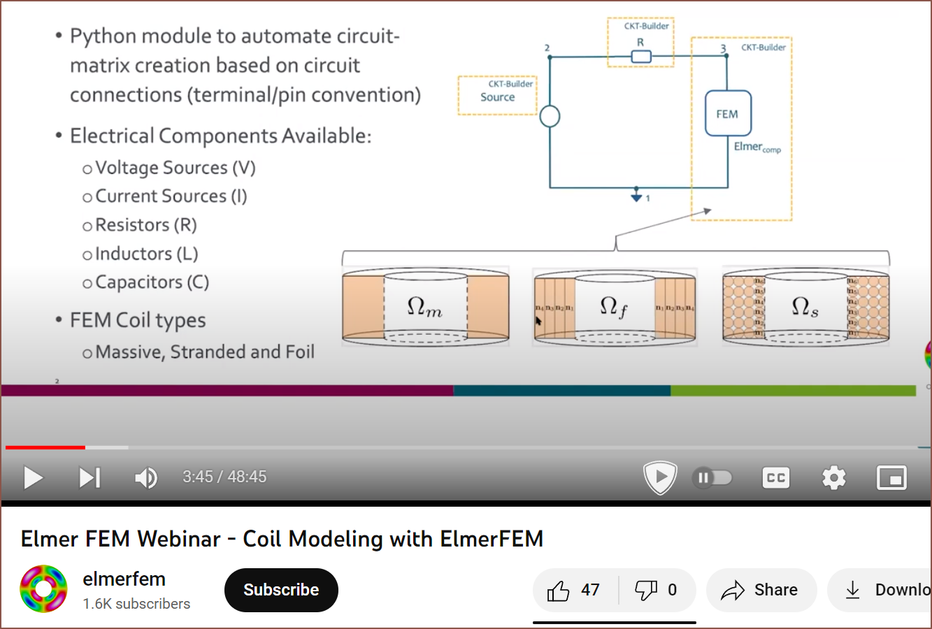
One program I found was Elmer, which seems more recent than FEMM, and I started watching this webinar:
This part is interesting because it shows that it can support the "stranded" and "foil" types of coils. It also sounds like this programs is rather large, so it's most likely going to take a while to learn how to use it.
The next Tetrinsic concept was going to be "Tetrinsic Concept4", but partially because this project needed a hero and partially because I was thinking about the intro music from the 33 second mark of the Fantastic Four: Worlds Greatest Heroes as I was thinking up all the improvements I could make from Concept 3.2X2, the internal code name is "Tetrinsic Concept Fantastic4".
The idea that forms the basis of this concept was from @RunnerPack all the way back in January, and is something I didn't really want to work on until after I actually had a proof-of-concept to test since it would involve more 3D printed / custom components. I wanted to be able to compare the off-the-shelf hardware solution to the more custom made solution.
Now that the 580KV motor is no longer available and I know that cogging should really be 0, I'm going to have to go through with a custom motor solution. While I was at it, I wanted to see if I could increase the stroke : body length ratio.
Initial thoughts
I thought about a solution for about an hour, and this is what I envisioned:
Tetrinsic becomes a linear BLDC motor with integrated hall effect and pressure sensors.
Part of the reason is so that I have more space to make and place coils.
The motor controller is already designed to let me bundle 4 motors to one CS pin, so I just need 2 CS pins for all 5 linear motors
I can use the 3 hall sensors that are sometimes installed into BLDC motors as the position encoder.
I only need 2 bent
tubes, and the turning pulley can fit inside the loop instead of outside
This assumes I
can create a surface that can turn on a 7mm diameter radius
Coils will be on
the top and bottom of the linear motor section, which makes the magnetic
field much more consistent and means that I don't have to worry too much
about air gap
The belt can be printed as a "Spiralise Outer Contour" (vase mode) of TPU
It can also be
made from a magnet-band-magnet sandwich, where 2 separate magnets are stuck on each side of a thin loop of material.
I later realised that this would mean that the Thumb Tetrinsic would have to be a different height than the Finger Tetrinsics so that the loop could go around them.
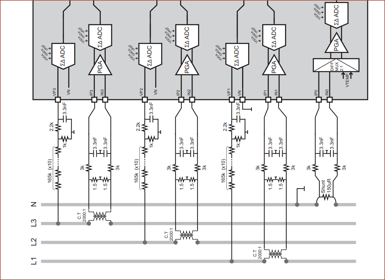
On the connector board, I can use a 5
input Sigma-Delta, 24bit ADC for the load cells and up to 5x multi-channel
16 bit adc's for the hall effect and current sensing
(I've been hearing multiple
times that the ADC on the esp32 isn't great)
Encasing the
top-down coils in a ferrous material should further increase the field strength between the coils and the magnet embedded belt.
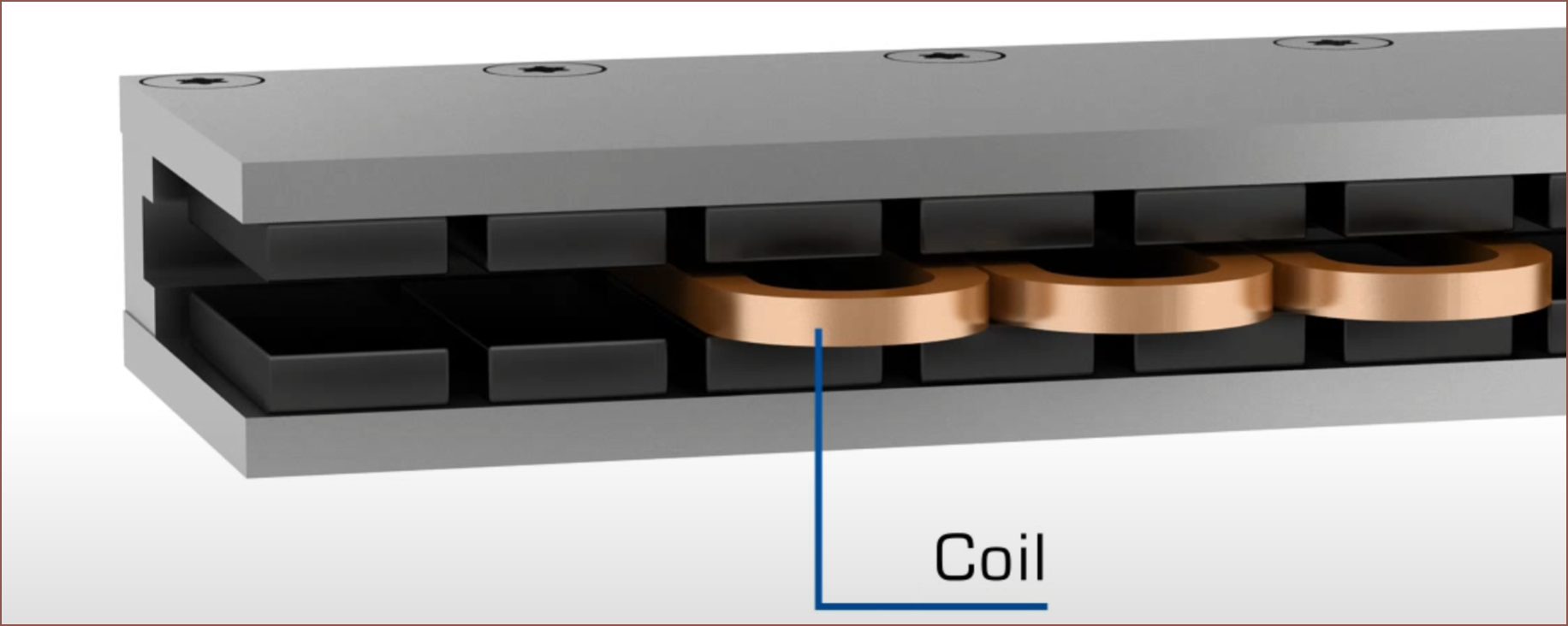
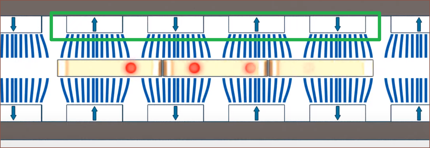
My idea is to take a linear motor like the one shown below, and swap the coils and electromagnets:
The design shown above also looks like a scaled up version of a voice coil actuator, which can be used for haptic vibrations.
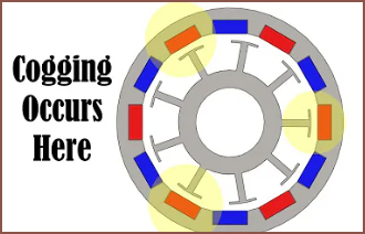
Anyway, cogging is eliminated because there's nothing magnetic in the stator. The first time I saw the video about cogging, I didn't fully grasp it, but the thumbnail actually does a good job of showing what's actually going on:
From the perspective of the magnets, the copper coil may as well not exist. The ferrous stator teeth it's wrapped around is a different story. Because of the gaps between the stator caps, there's actually an imbalance of attractive forces. (remember, magnetic materials are attracted to both north and south poles of magnets). I'd imagine that, to solve it, you'd either need to remove the ferrous stator entirely or design the stator such that the attractive force is equal across the entire perimeter.
Magnets
The first reason why Me In The Past didn't think that the embedded magnet idea would work was because I was mentally simulating with 1.5mm cube magnets. This was back when I was working on Tetrinsic (Concept) 2.0.
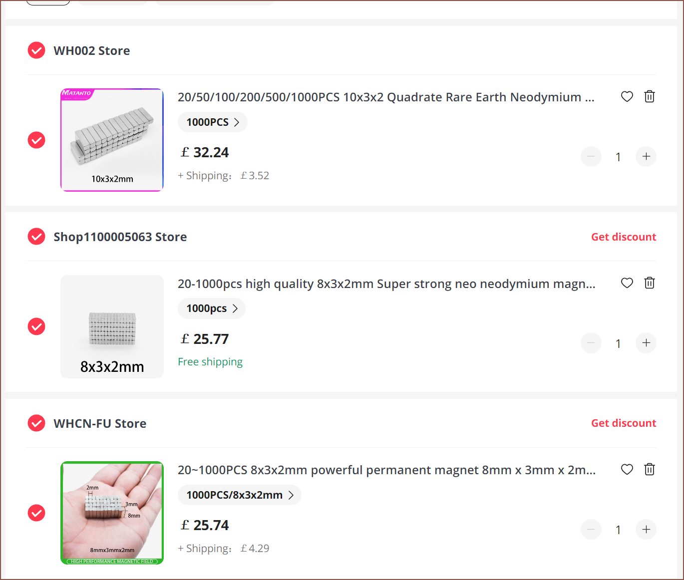
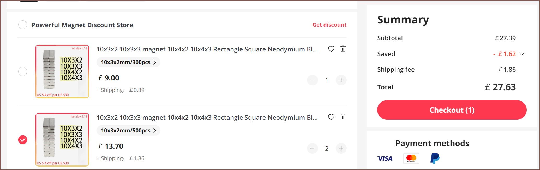
I measured the magnet length in the 580KV rotor to be 8mm and the stator laminations to be 7mm. Thus I started looking for an 8*2*2mm magnet. That doesn't really exist, but an 8*3*2mm, 10*3*2mm and 10*3*3mm magnet does. Here are some that I found:
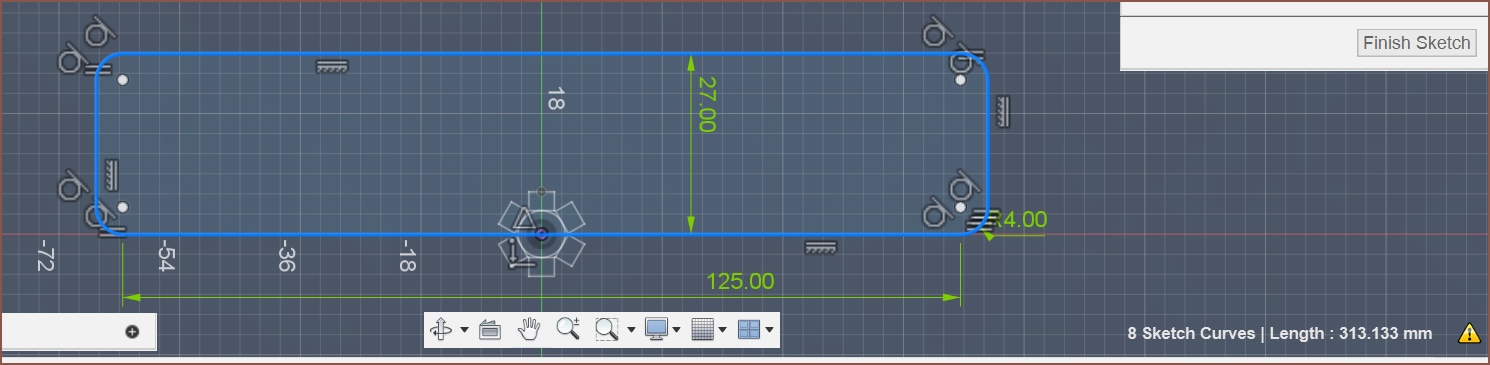
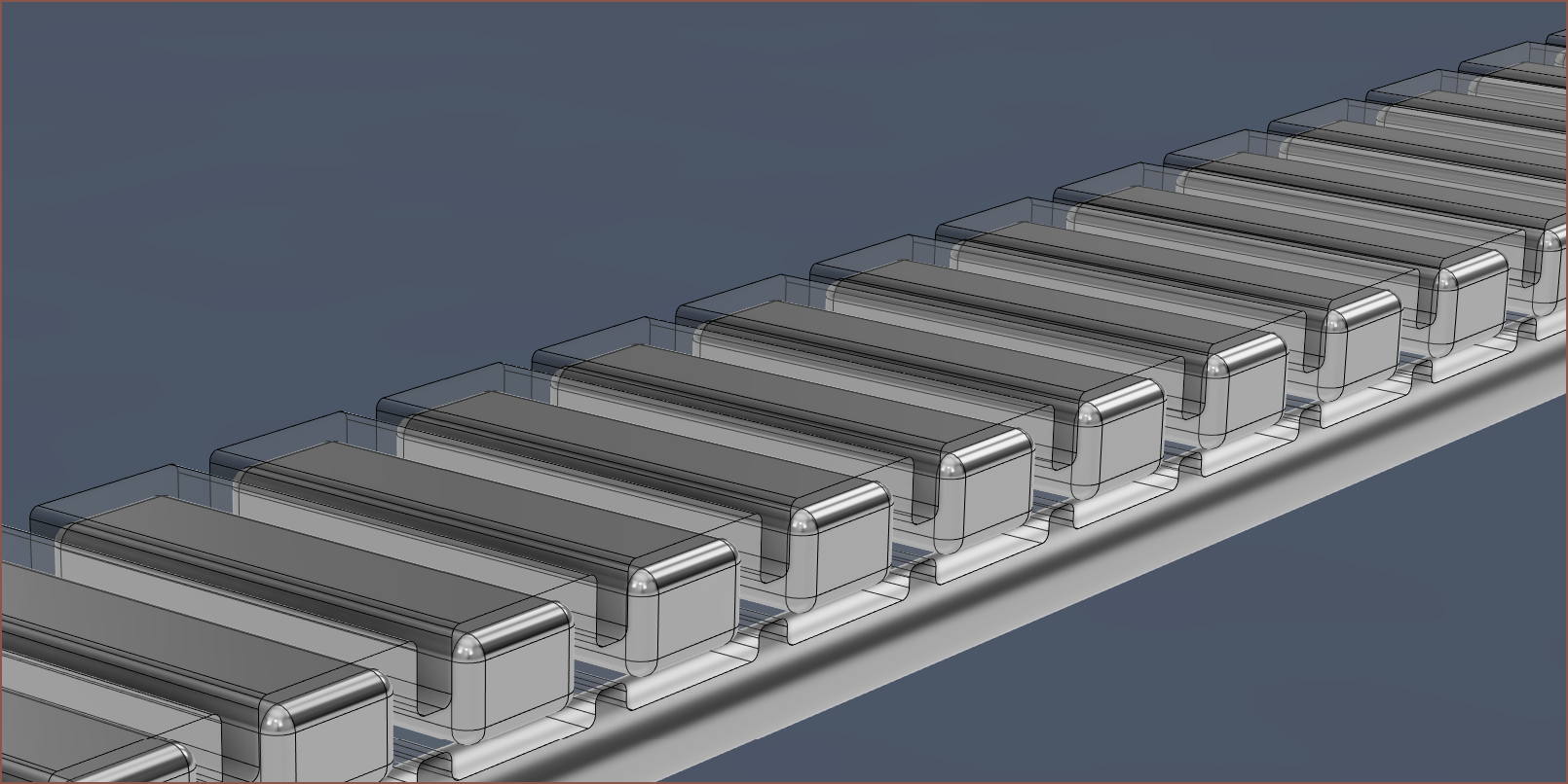
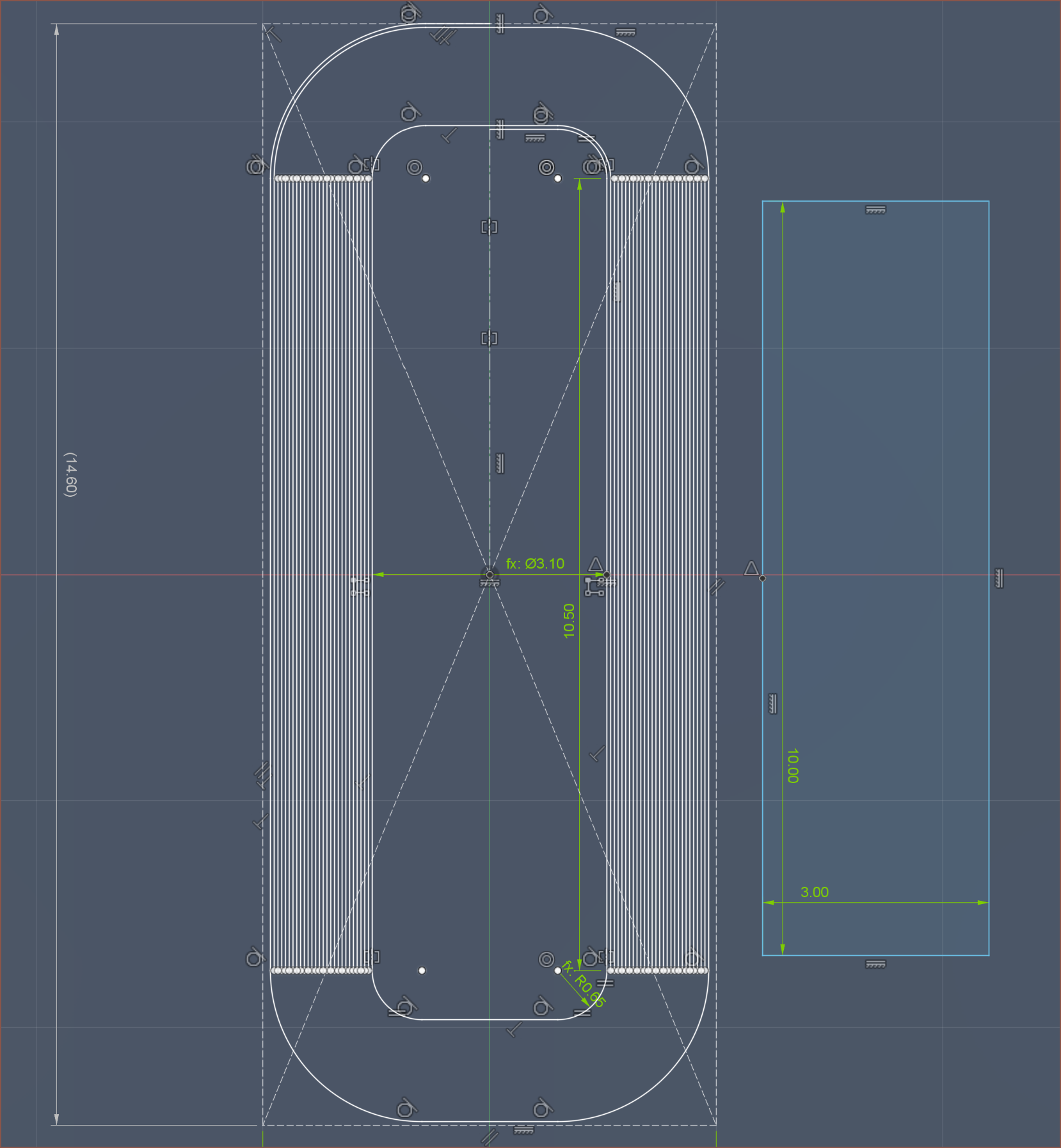
Then I sketched up an rough estimate for the overall loop:
313/4.2 = 74.5238. I require "pole pairs", which means the amount of magnets needs to be multiples of 2. Thus, the min amount of magnets needed for the belt is 76.
I went with 10*3*2mm magnets because the motor strength should be 25% higher, I've got a better chance of fitting the pulley in-between the sliding rods and I have the opportunity of going to a 10*3*3mm magnet if needed. For now, the 2mm magnet as the benefits of being able to obtain a slightly shorter Tetrinsic and it's more obvious than the 3*3 which faces have poles and which are just the sides. The belt would also be lighter, which means external forces would have less of an effect on the load cell readings. More on that further into this log.
This is what the belt would look like on the steel rods:
Print Material
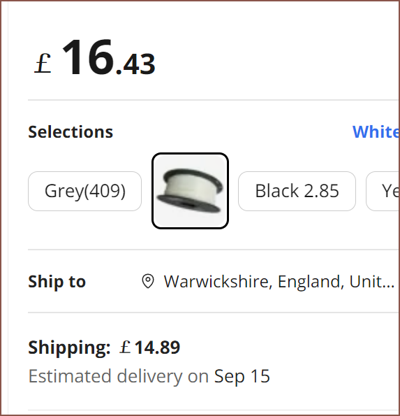
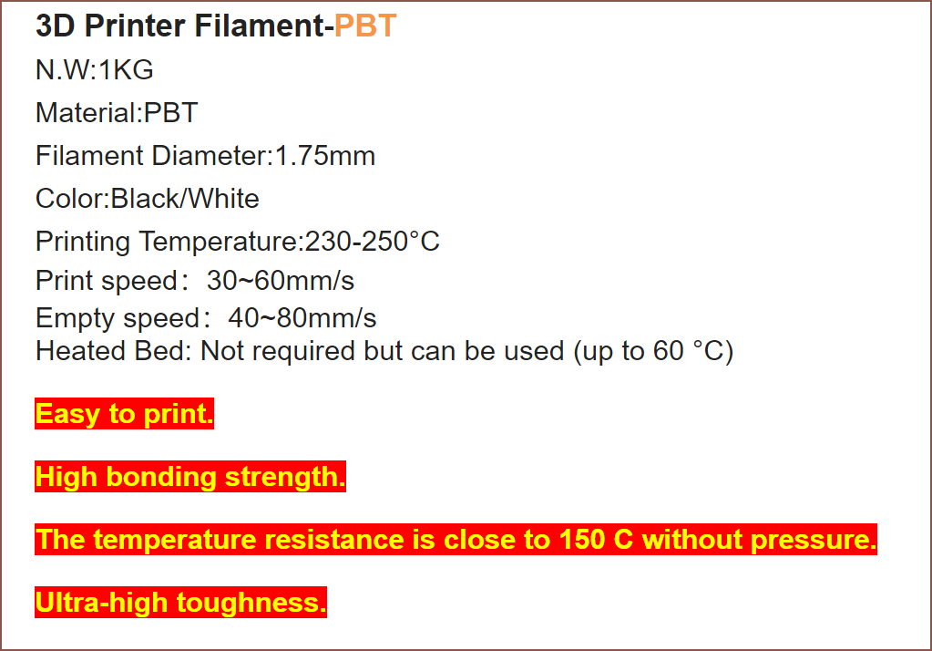
The obvious choice, at least on paper, is PBT:
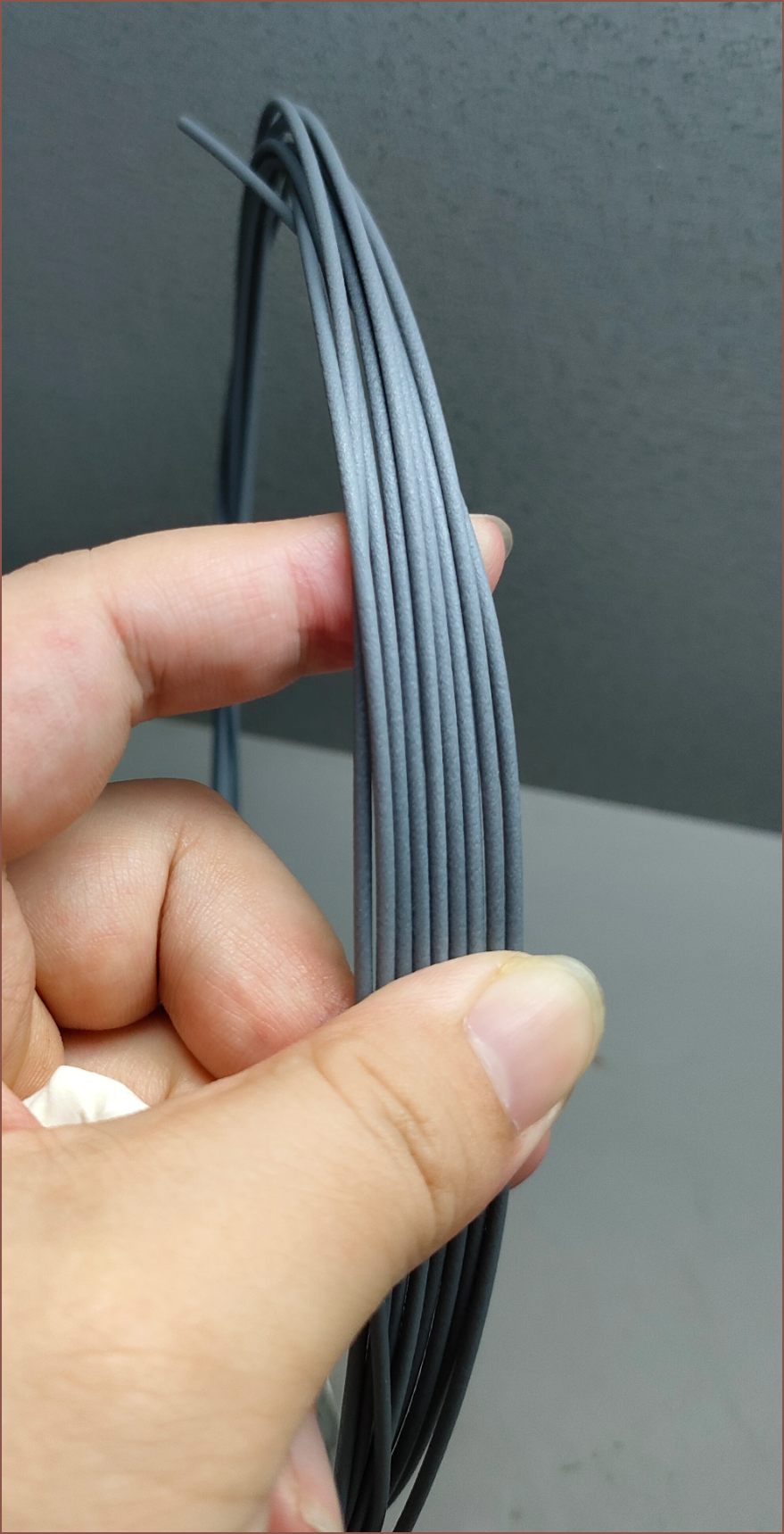
Easy printing? Doesn't even need a heated bed yet has a working temperature of over 130 degrees Celsius? High inter-layer bonding and toughness? I haven't tried it, but it's essentially obtainable unobtainium. I even tried making my own. I asked the seller what the grey looks like and I believe it looks great:
From my experience trying to extrude pellets into filament, I can only imagine the only imperitive step before printing this material is to print a temperature tower. This material has a very sharp melting point.
Accelerometer
The mass of the assembly responsible for measuring the pressure of each finger is now higher, meaning it's even more likely that acceleration and orientation changes will cause Tetrinsic to think that it's being pressed when that's not the case. Thus, I need a 1 axis accelerometer that's in the same axis as the force sensing part of the load cell.
Long story short, the BMI160 is still the best chip for this. I looked into the sample rates, and it looks like I should target 800 or 1600 samples per second:
The amount of samples per second directly affects the latency of the overall system. The last thing I want to find is that my fingers are feeling a haptic event for one layer but the force I'm applying means I'm already in a layer above / beneath it.
As long as the data is clean, 800SPS should be fine.
New Feature: UVC sanitation
Whilst researching and planning out this concept, I had a realisation. The belt can be electronically moved out of view, I could place a UV LED on the underside and heavily touched items such as keyboards and smartphones gather a lot of microorganisms. I also remember the below video I recently watched on "Big Hand Dryer" vs "Big Paper Towel", namely the part when Half As Interesting said "[Big Paper Towel] hit 'em on hygiene.".
I quickly searched to see if UV LEDs have been used to sterilize keyboards, and I found this video from Kensington on a product called the UVStand:
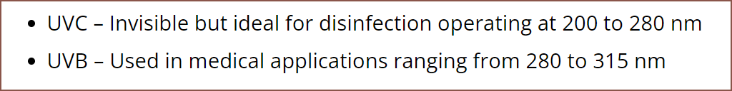
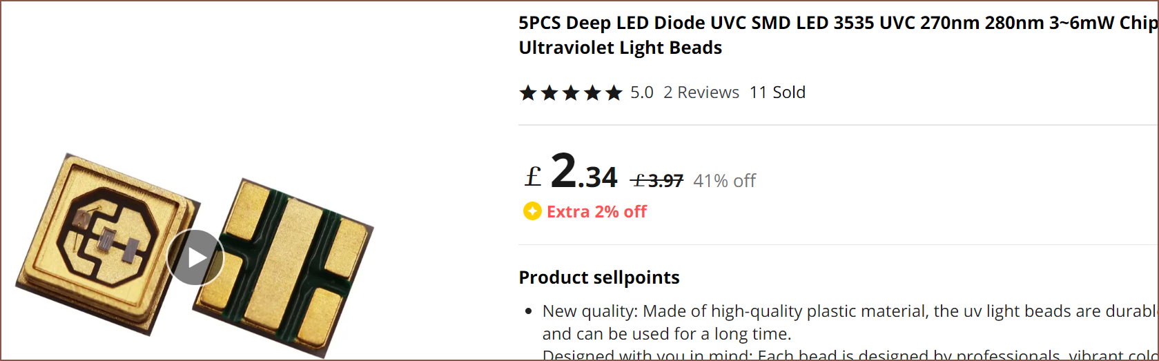
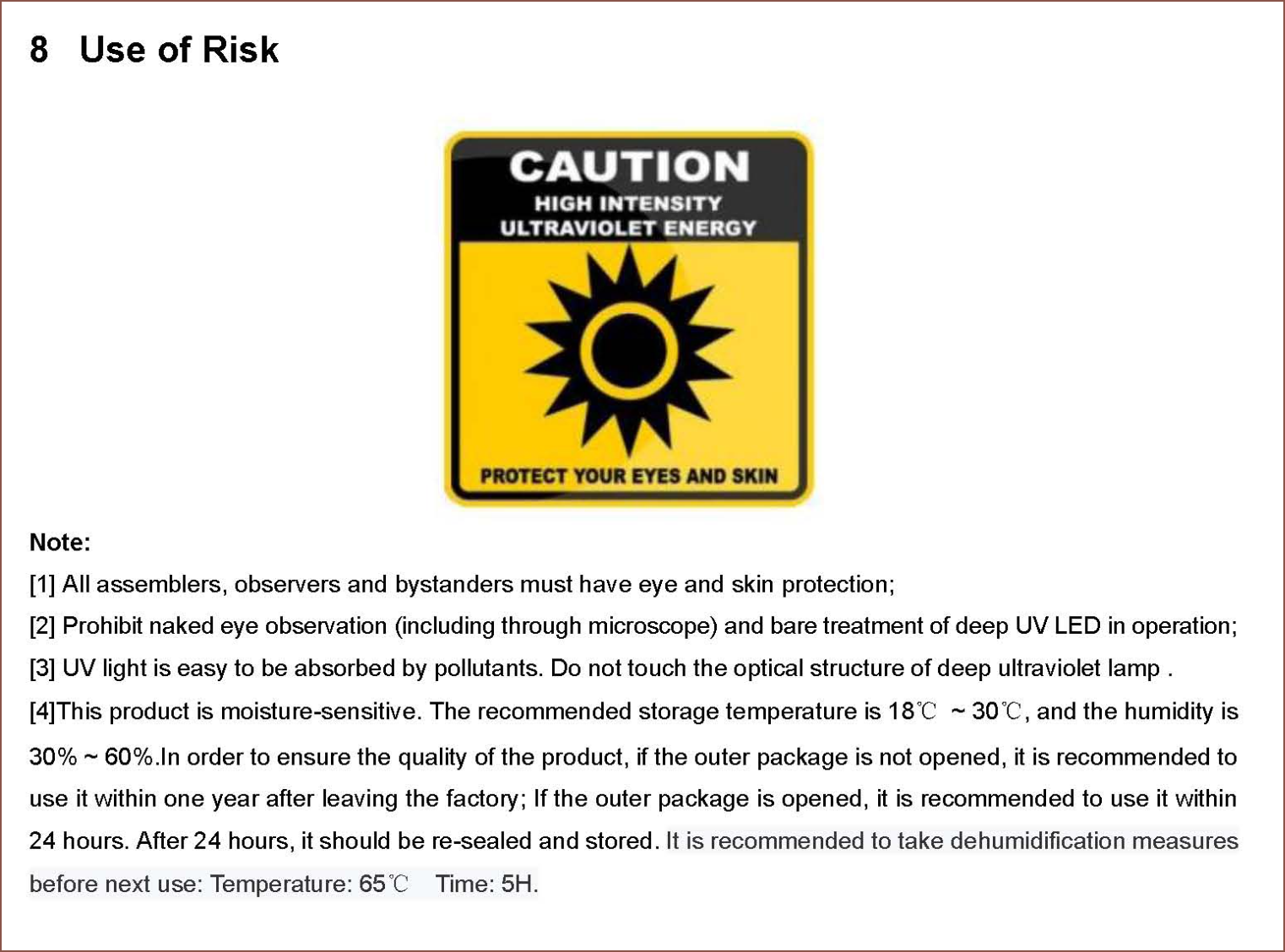
Then some quick research on wavelengths, protective eyewear and purchase options followed:
Coil Creation
I knew that the coils were going to be the most tedious out of this entire operation, so I wanted to look into strategies.
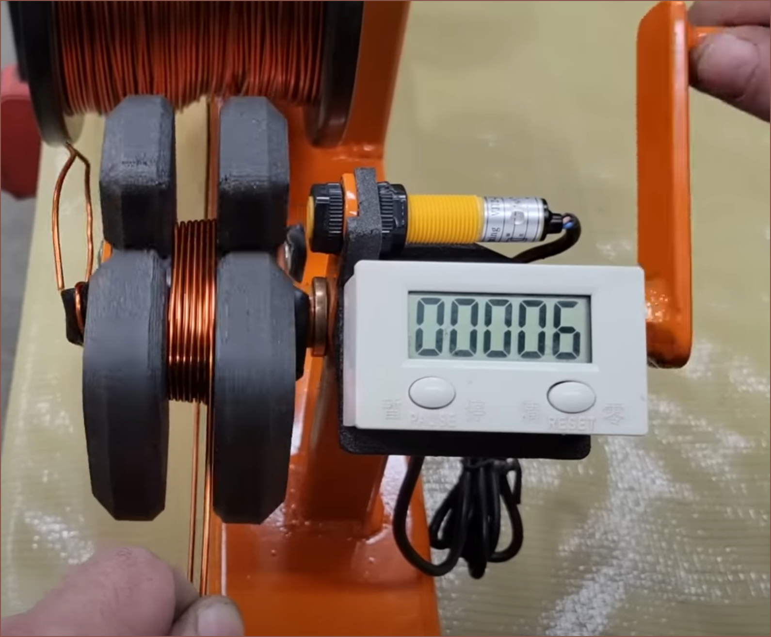
This video on YouTube said that coils of copper inside the perimeter of the magnet wouldn't generate any energy (he's making a wind turbine), and seems to be confirmed by looking at a StackExchange question:
For this application, the Kv should be as low as possible. This means that the turn count of the motor needs to be as high as possible. However, the higher the turn count, the longer it would take to coil, maintaining coil shape quality.
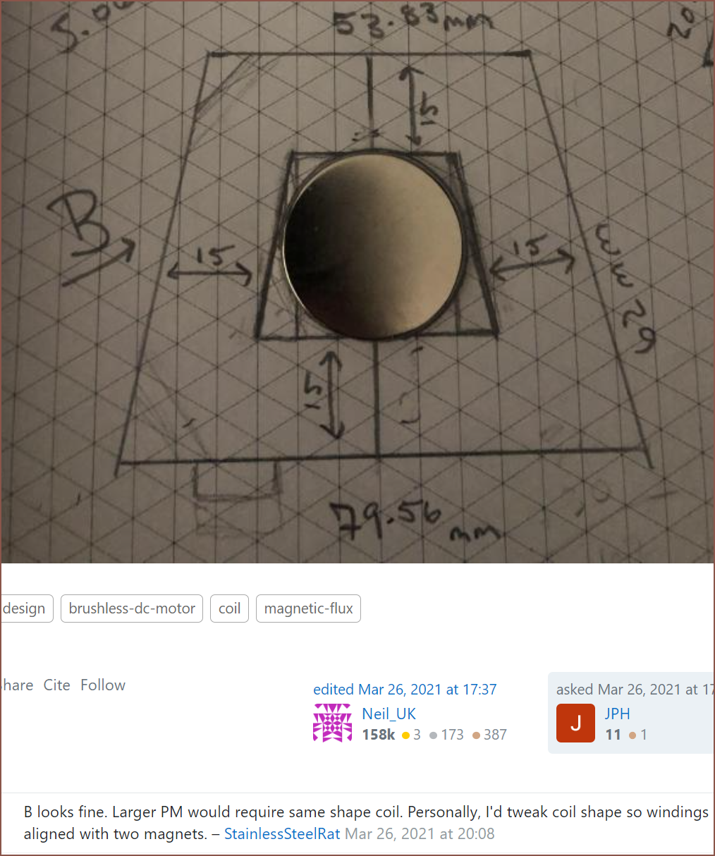
On my research travels, I found this image:
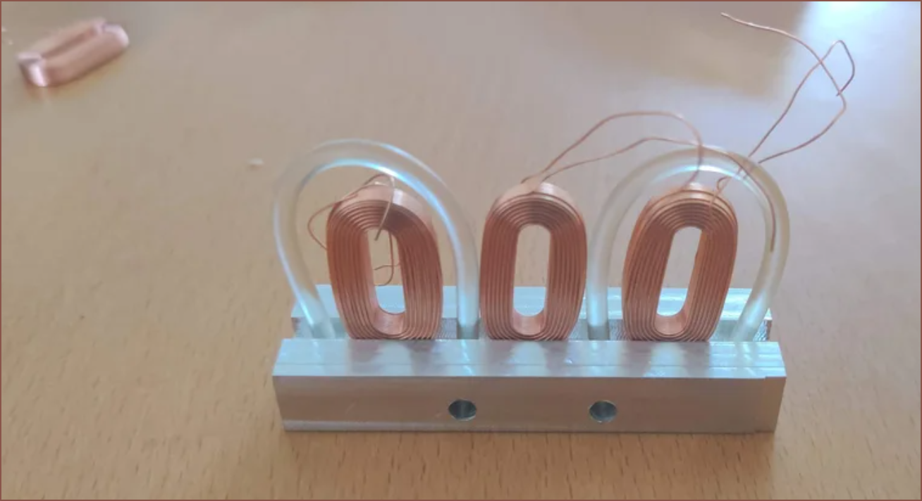
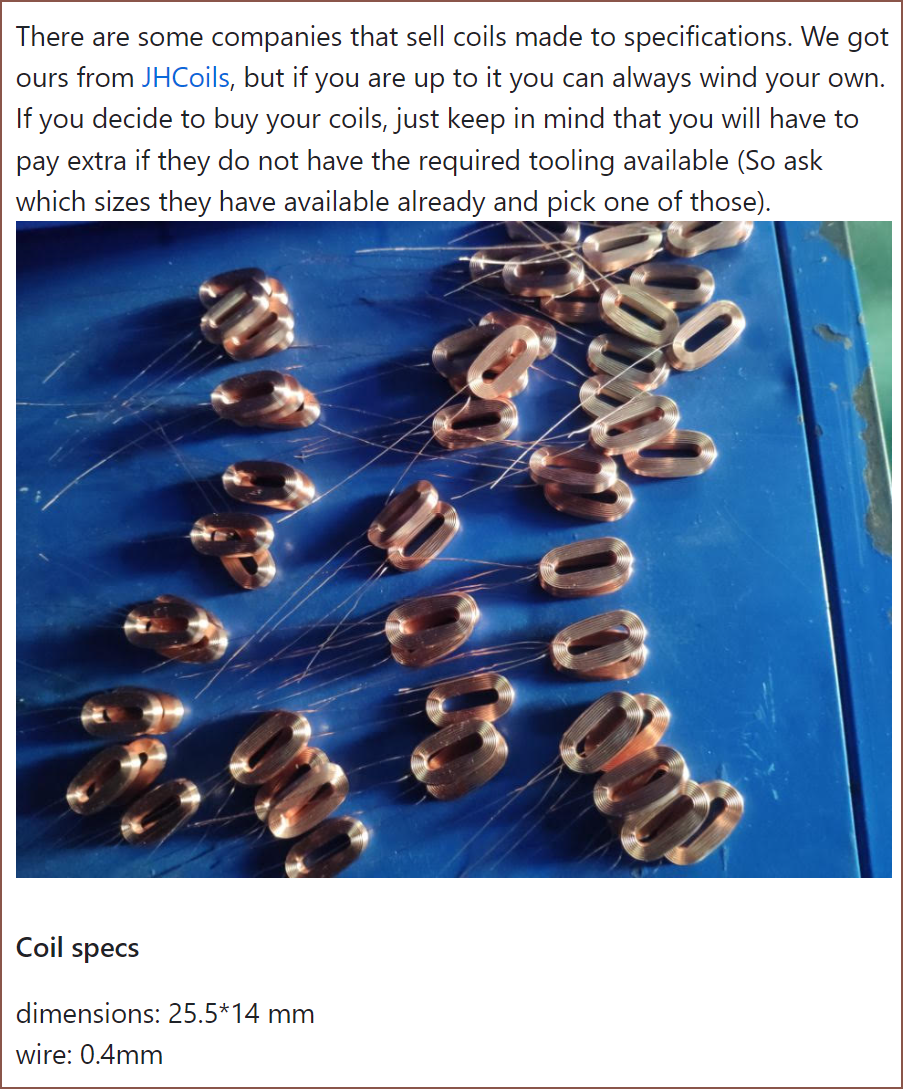
The coils were actually bought:
It doesn't seem like they'd have the size I'm looking for:
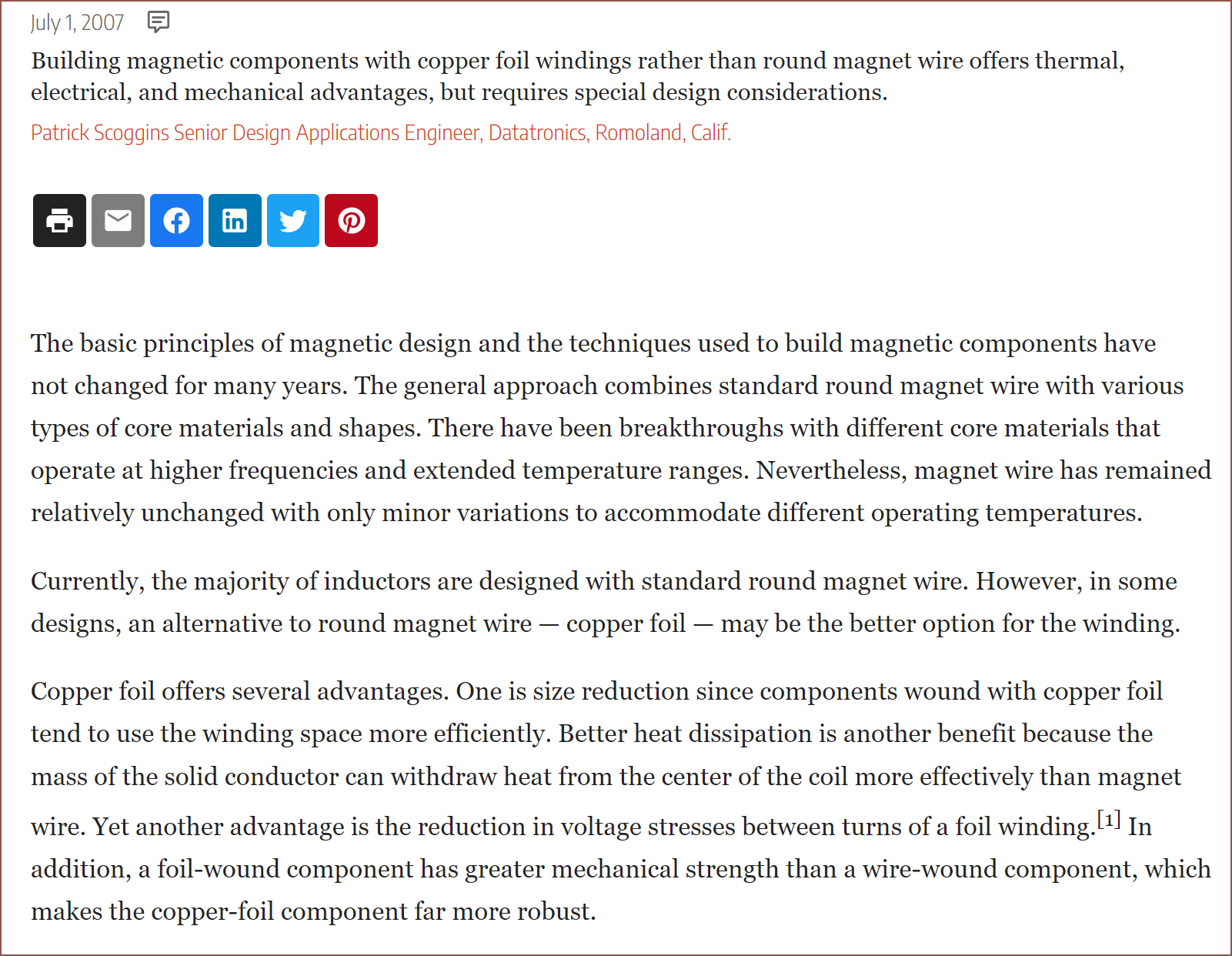
So I did some more mental simulations and for conductivity of heat, electrical resistance, number of turns, ease of coil manufacture and quality of coil geometry, I'm not really seeing the drawbacks to using copper foil here:
Look at that. It already looks like a perfectly wound coil.
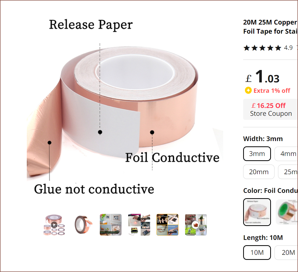
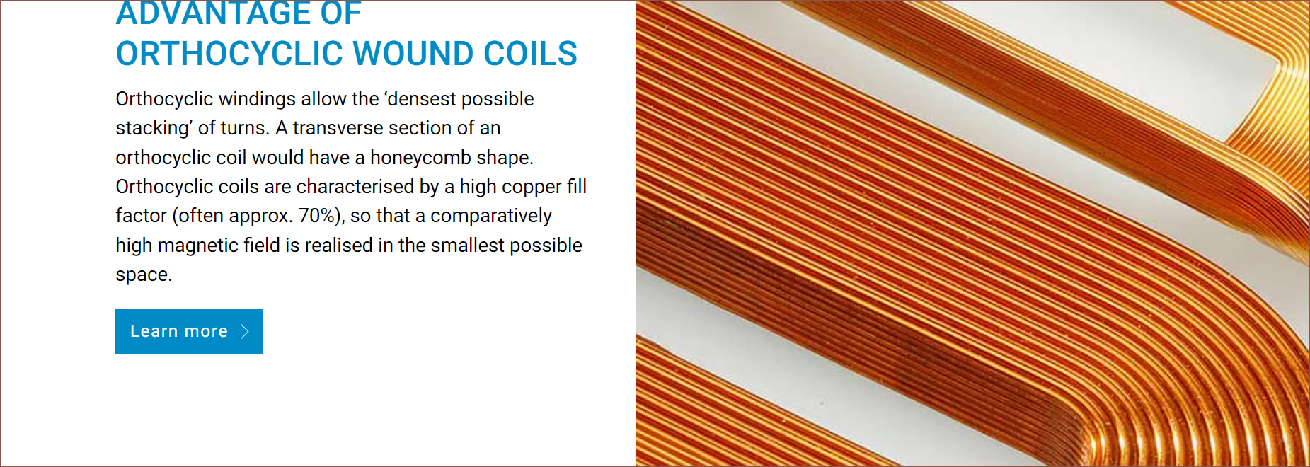
I looked around and found one with a datasheet, called the AT0525 35 Micron Copper Foil Shielding Tape. It's got a foil thickness of 0.035mm and an adhesive thickness of 0.03mm for a total thickness of 0.065mm. I did some more research and found out about orthocyclic wound coils.
The amount of spacing needs to be 3 coils for every 4 magnets.
I'm planning on using a 4.5mm magnet-to-magnet spacing, which means that the max coil width can be 4.5mm*4/3 = 6mm.
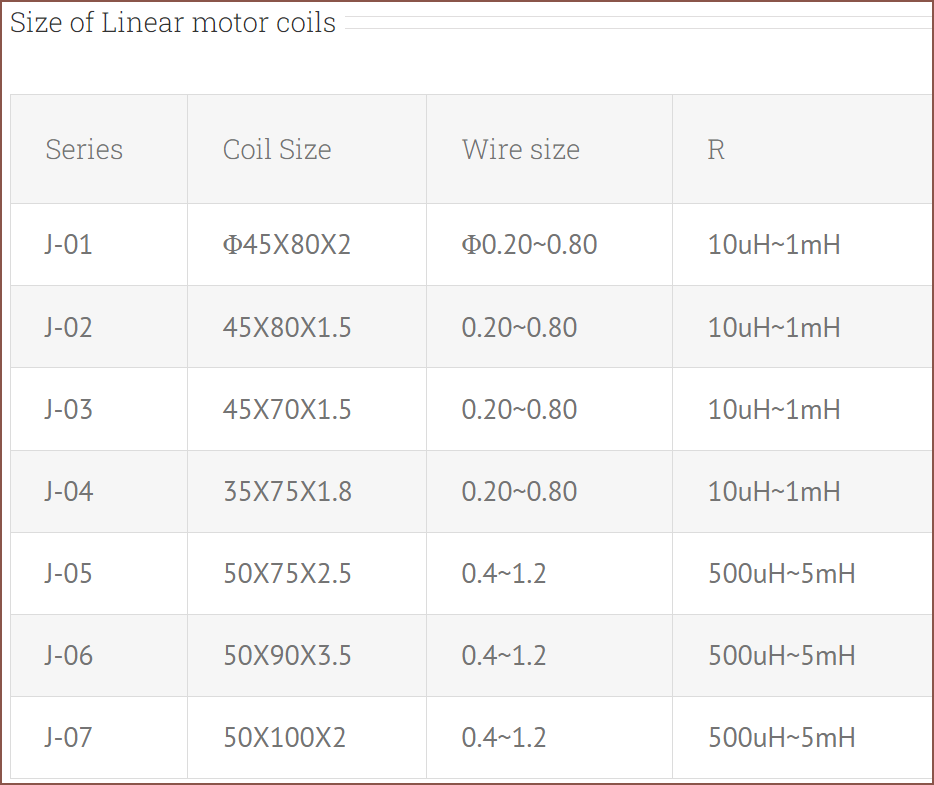
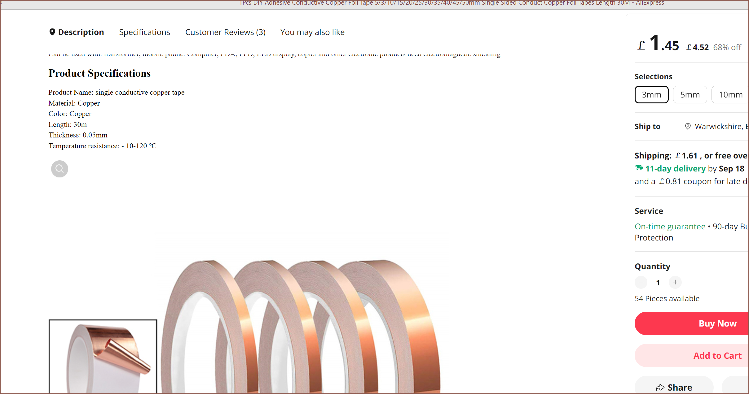
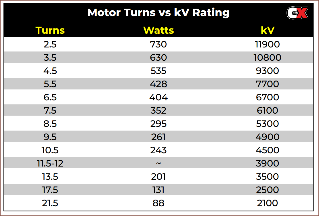
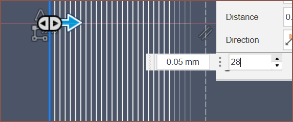
I found this 3mm foil that is only conductive on one side which has a thickness of 0.05mm and a length of 30 metres. I also found this table that gives me a rough idea as to the turn count relationship to Kv:
It seems that I can fit about 28 turns and still have space for an insulator such as Kapton tape to go around the entire coil.
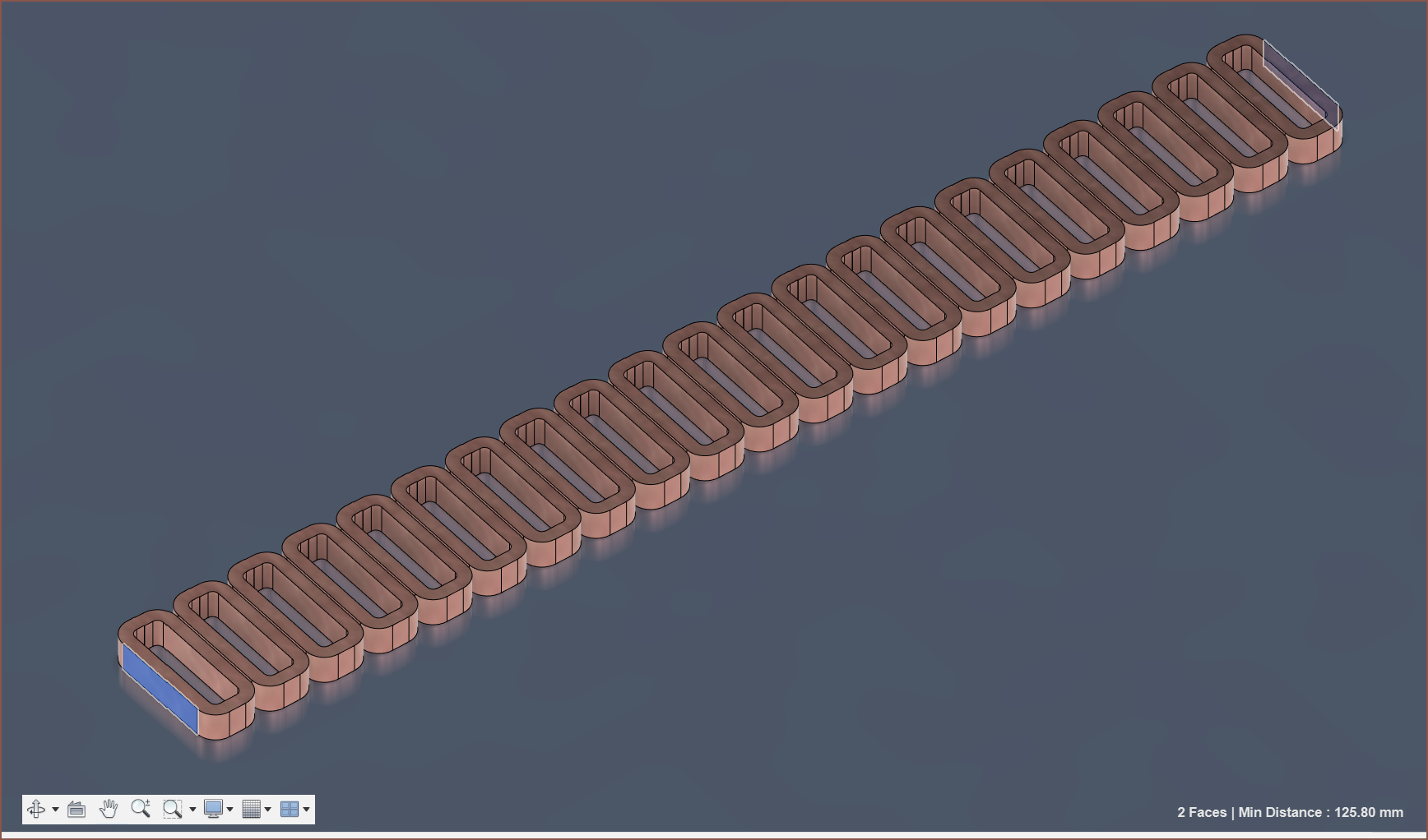
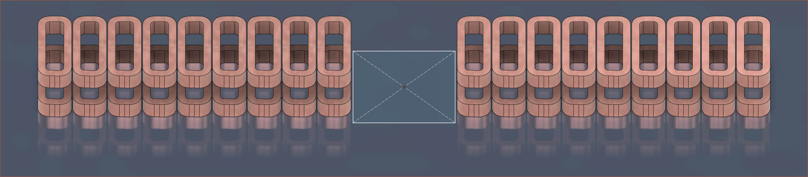
Conveniently, there's an odd multiple-of-3-set that is just a tad longer than a single solar panel used in Tetrescent.
The middle set of 3 coils are removed, and in their place is the 17.5*17.5mm PCB(s) that have the accelerometer and UVC LED. As you can see, each Tetrinsic would use 36 coils, meaning that I'd have to make over 360 of them for 2 Tetrescents, using over 305 metres of foil in the process. Not having to precisely wind thousands of metres of 0.1 - 0.2mm wire onto a 3mm tall coil is the main reason of attempting this foil method. It should be possible to create 9 foil coils at once if I design a suitable jig.
The Analog To Digital Converter
This was the part that took the most time and research. This was mainly because it was the difference between Tetrinsic costing £17.20/ea and as much as £23/ea (which is a difference of £50 for 10 of them).
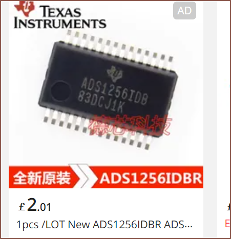
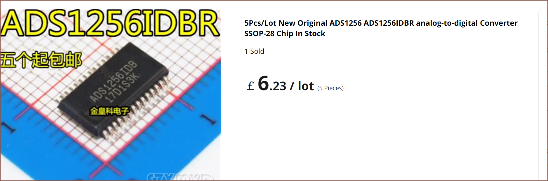
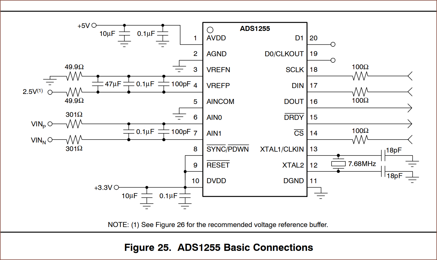
The first thing I did was search Digikey and found out that the ADCs that I can use still start at over £3/ea. Thus I quickly turned to AliExpress and found the ADS1256:
£2 is kind of odd, since on Ti's site, it's like $12:
Well there were many sellers selling it at under £2/ea, with the cheapest being £1.50 after tax:
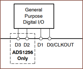
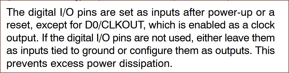
The first things I noticed was that I could save a clock pin and use a crystal (though I'd rather avoid it) and that there was even an IO extender in here:
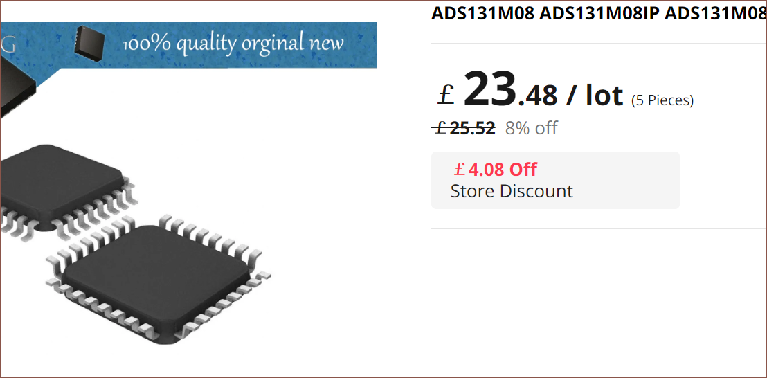
The ADS131 series is a lot rarer on AliExpress. I couldn't find the M06 but I was able to find the M08 edition:
This is £5.80/ea after VAT.
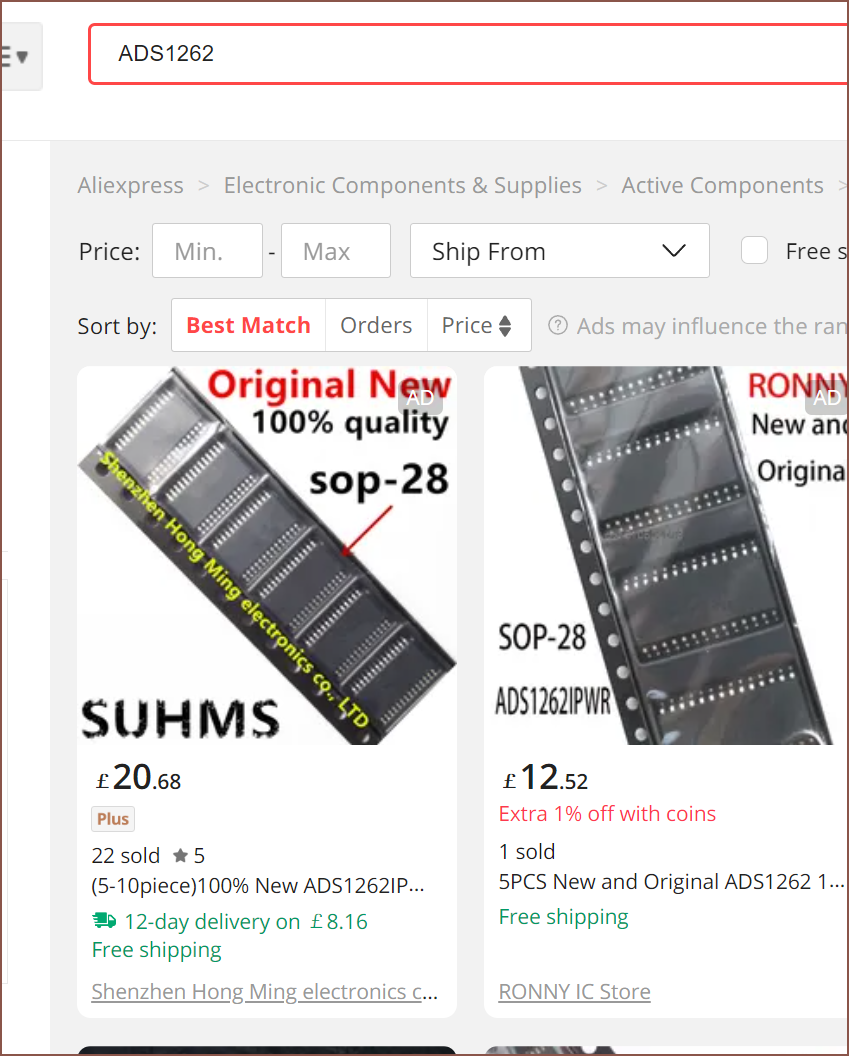
I then found the ADS1262, which is a 32 bit ADC
This thing also has IO, but it's shared with the ADC inputs.
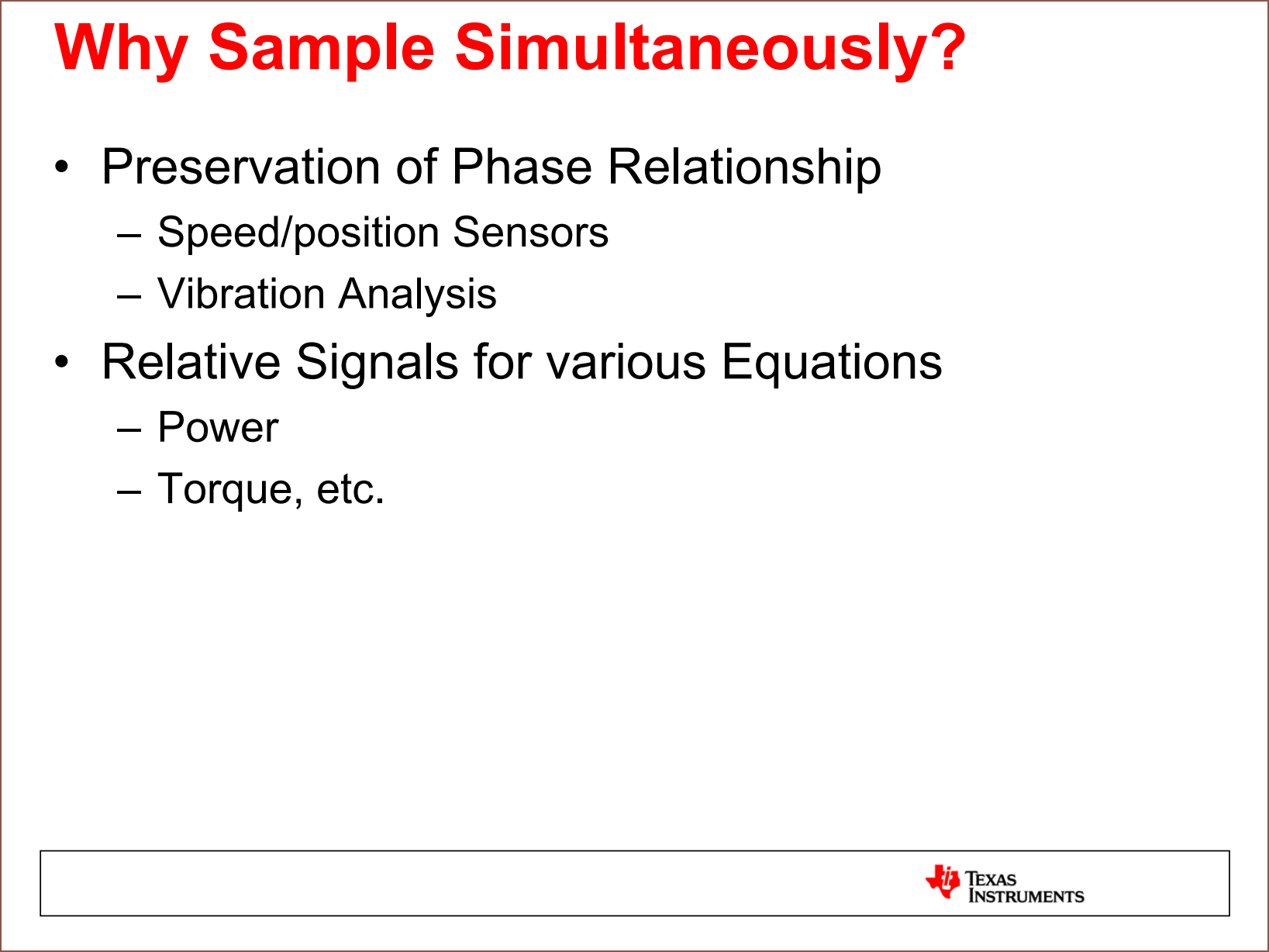
Now, the ADS131 series is the only ADC I've found that can simultaneously sample. The other two, as well as the MCP3564R I'll mention shortly, only have a single ADC. There's also the ADS1263 that has a 32 bit and a 24 bit ADC, but the 24BIT ADC can only do 800SPS (which I was planning to split across 3 current sense pins), the datasheet suggest that this ADC has less than 12 bits of effective resolution at that full speed, and costs about the same as the M08 on AliExpress. This is one notable slide from Ti that I saw when considering my options:
Moving on, the less things I need to sample, the better. It turns out that I could only sample 2 of the 3 sense pins and then calculate the current in the 3rd one:
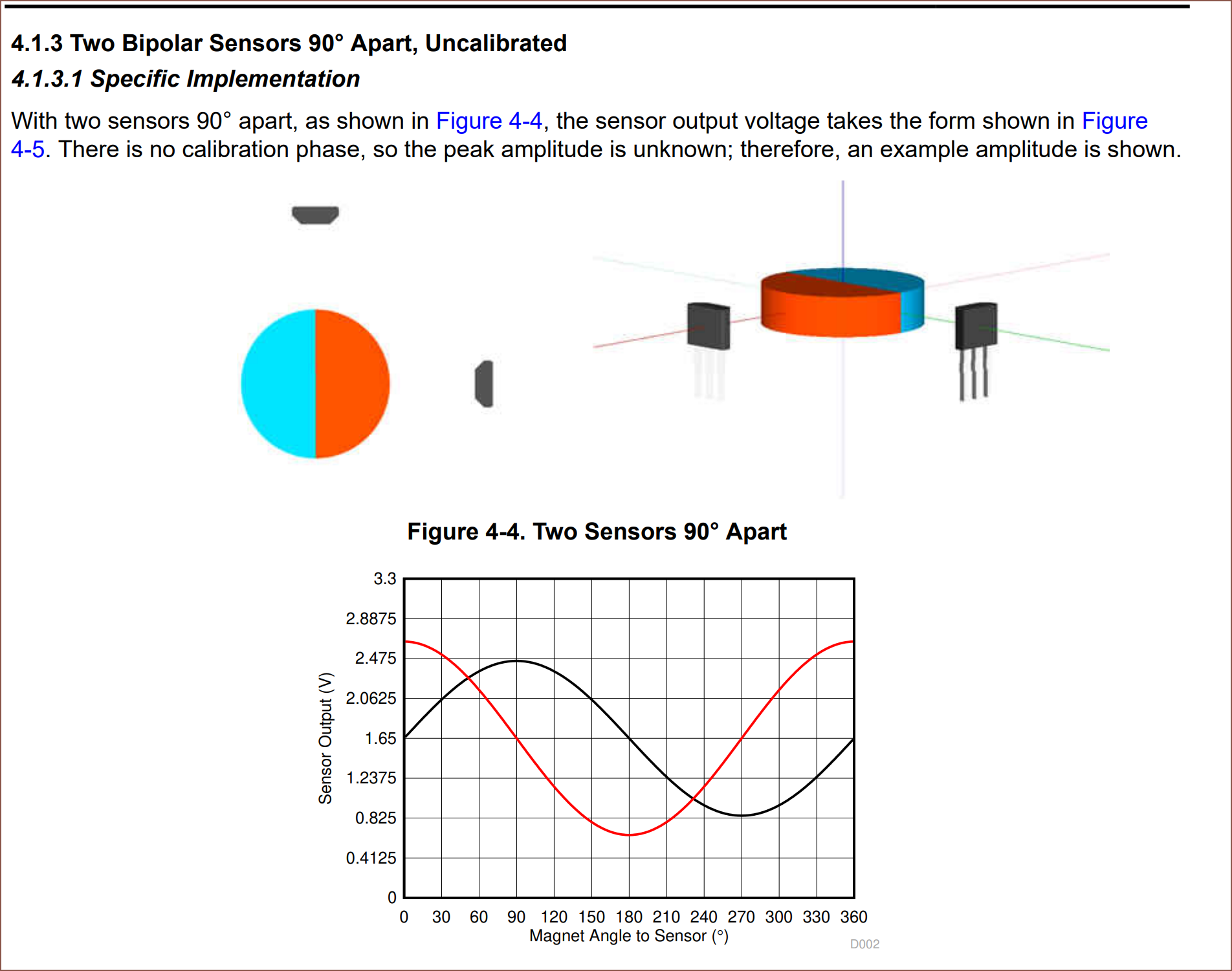
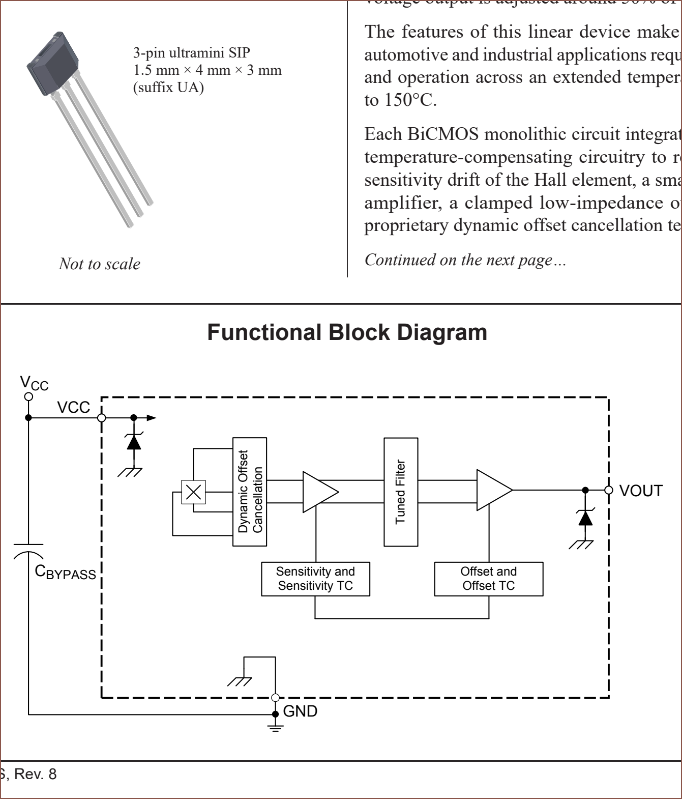
I'd imagine that I can also have 2 hall effect sensors for position:
A little side note is that these sensors have more in them than I thought:
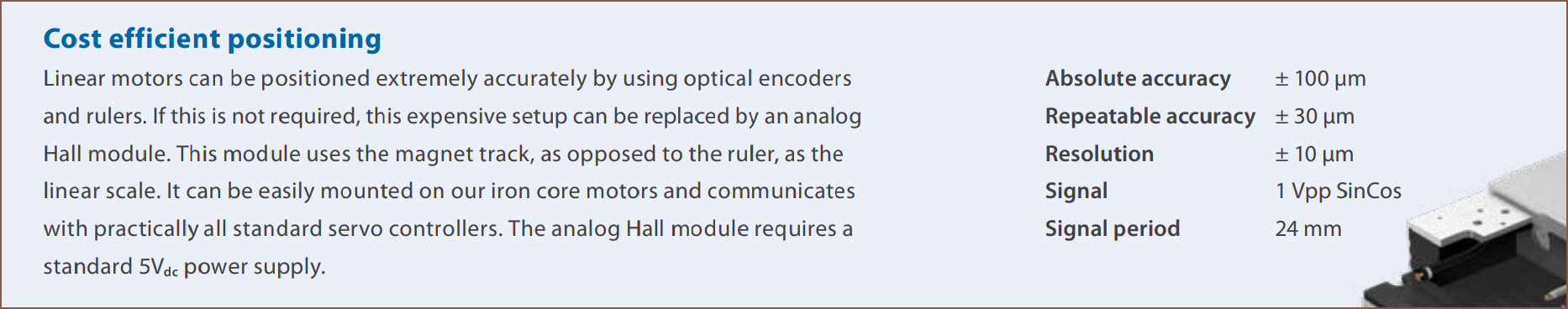
There's the below linear motor that, even though it's only got a 34mm mover length and 2mm thick magnets, it can generate up to 10N of continuous force and also uses hall effect sensors to obtain position from 2 signals:
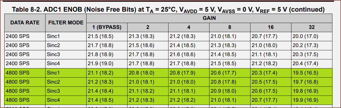
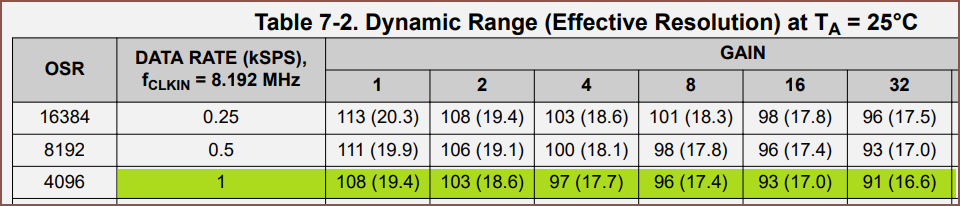
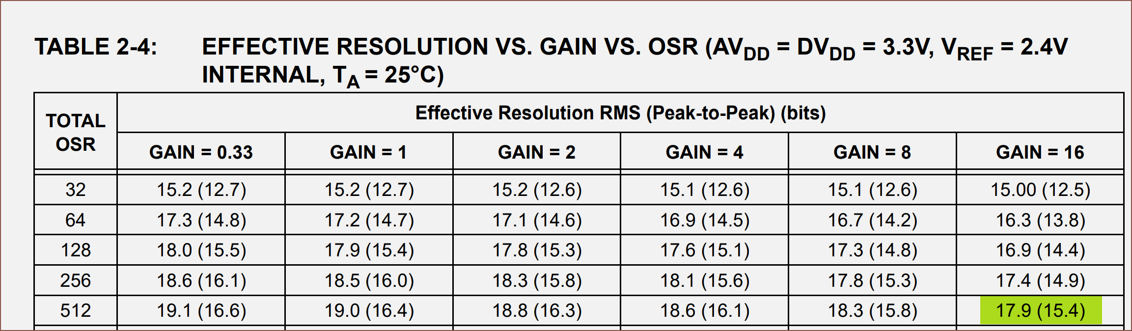
Back to the ADCs, that essentially meant that I have 5 or 6 sensors to scan, meaning that I need 4000 - 4800 SPS if aiming for 800 SPS across all channels. Below are the Effective Number Of Bits (ENOB) of some of the options.
32 Bit Multiplexed:
24 Bit Multiplexed:
24 Bit Simultaneously Sampled:
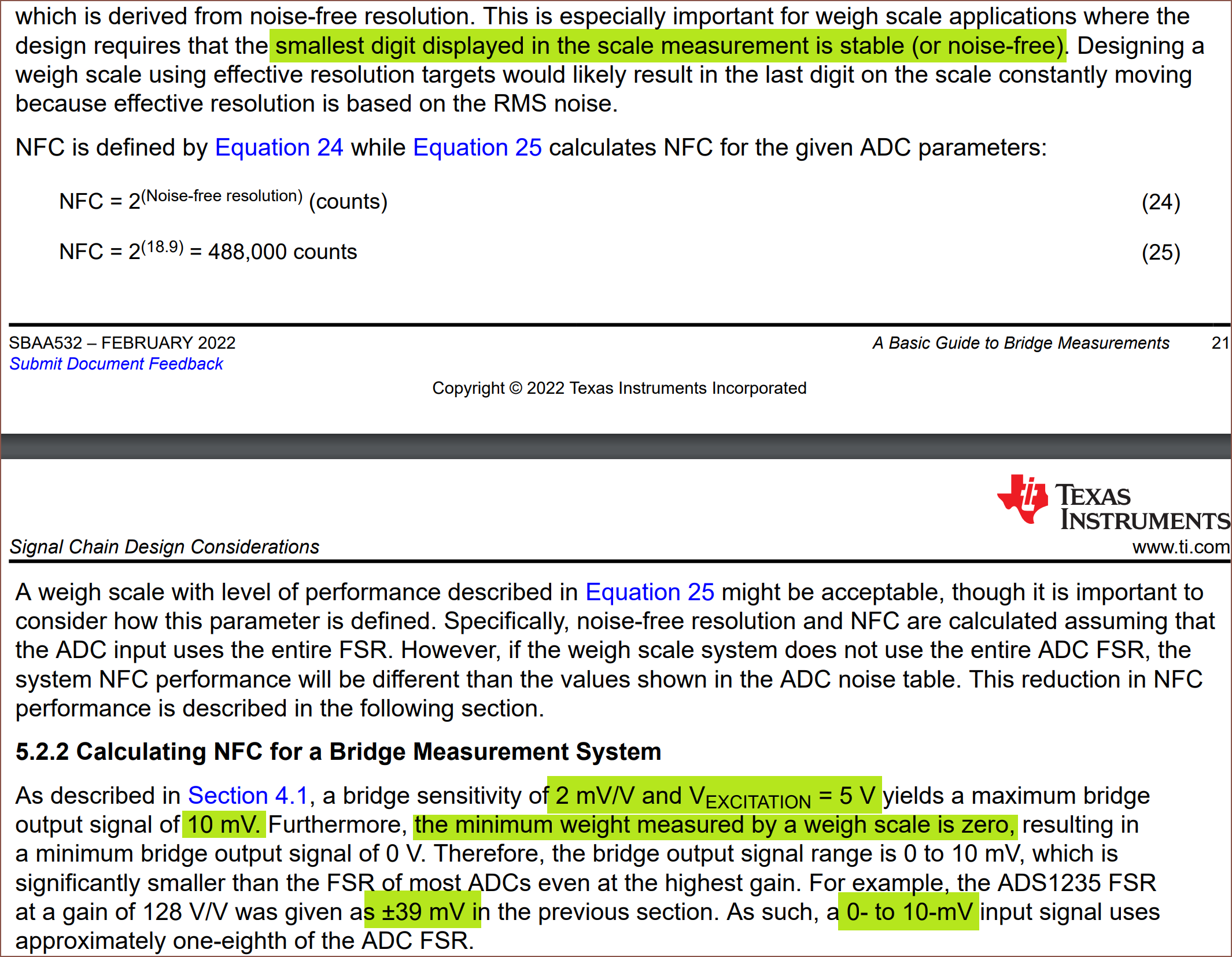
And some research suggested that to convert Effective Resolution to Noise-Free Resolution, I take away 2.7 from the number. Looking at the difference of the 24-bit mux, I believe that is the case.
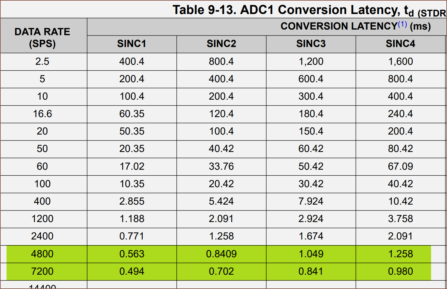
I then looked into scanning the inputs, and found this in the 32 bit datasheet:
1/4800 * 1000 = 0.2083 ms. The only data rate option that can get that is the 38400 SPS option. Looking at the noise free bits, it tanks to 12.5 across the board doing that.
The 19200 SPS option has a settling time of 0.337ms, resulting in a top frequency of 2967Hz. I'd have to go down to 400SPS to use this. That still exceeds the touch sampling rate of most gaming smartphones (360SPS), but I'm not sure if it's fast enough for haptics. It also increases the latency between the measurement of the sin and cos hall effect sensors. The above table uses an external 5V reference, and it sounds like the reference voltage only affects 38400SPS:
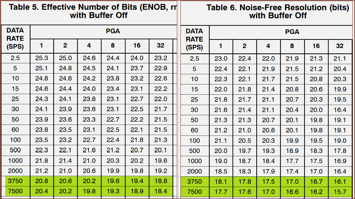
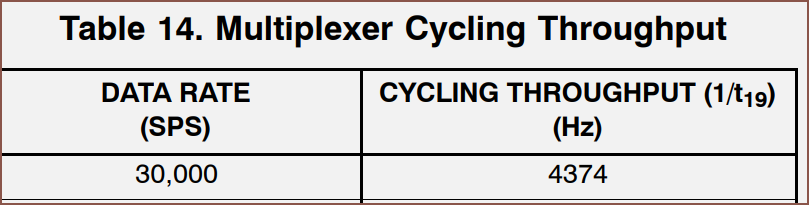
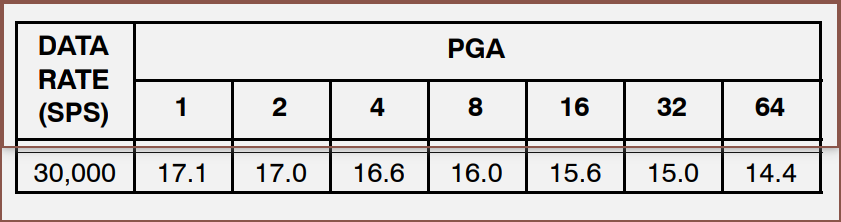
For the 24 bit mux, it's maximum is 4374Hz:
Noise Free Bits
By sampling 2 sense pins, I could still obtain 800SPS and I'd get 15 bits at PGA = 32.
The reason why I'm looking at the noise-free bits is because of this:
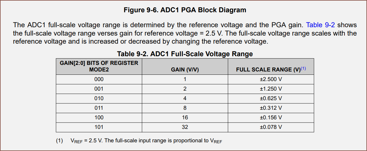
Now, the load cell (well, a very similar load cell to the one in the precision scales) states that it's excitation is 1mV +/- 10%. That seems to mean that with a 3.3V source, I'd get +/- 3.3mV of full scale signal. The below is the 32 bit ADC's mention of PGAs:
This ADC has an internal 2.5V reference.
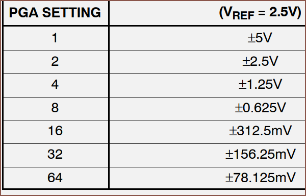
That's like... 78mV. For the 24 bit mux, it's the same for the highest PGA value:
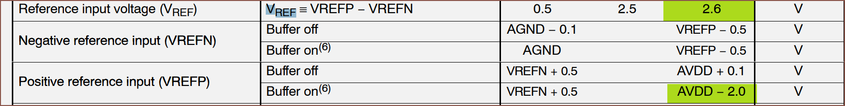
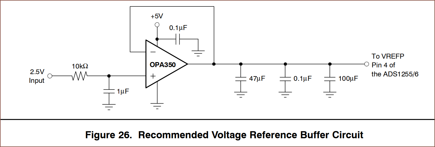
The issue is that it actually doesn't come with a reference voltage source:
I can't use 3.3V for the positive and GND for the negative terminal because Vref has to be less than 2.6V. Also, the buffer needs to be kept off unless I want to be using something like a 1.25V reference voltage.
Overall, there's something like 12 components I need to also allocate PCB space for to even use this chip. I could always put this on the connector PCB, but I'm not sure if it's a good idea having a reference voltage trace spanning across the entire device.
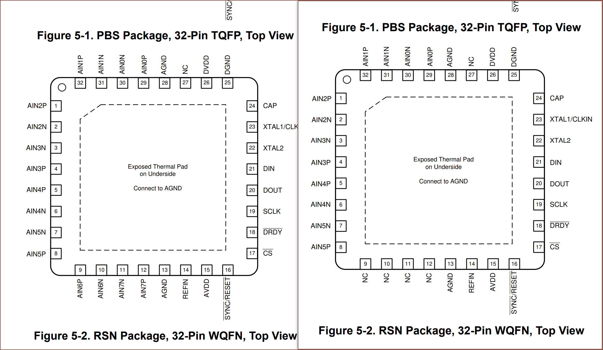
Moving on, it turns out that the M08 and M06 share the same packages and pins, just that the latter (on the right) has 4 more NC pins.
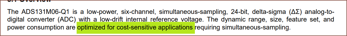
I'm not sure why Ti made seperate datasheets for all the chips in the ADS131M0x range. It's also a bit painful that they said it's "optimized for cost sensitive applications" when it's easily the most expensive chip:
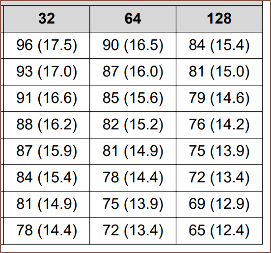
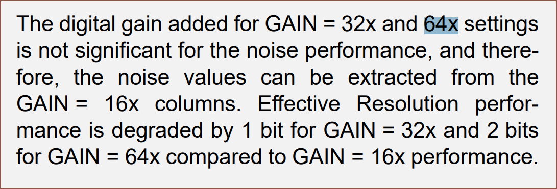
Anyway, most everything in them are identical and there's something I noticed about the ENOB:
As you can see, PGA=32, 64 and 128 don't exactly do anything. The signal gets doubled, but then you lose 1 bit of precision. It's essentially like just multiplying the values by 2 in software. The FSR at 128 is +/- 9.375mV.
Side tangent: There's also chips that sense voltage and current:
I thought it was quite cool.
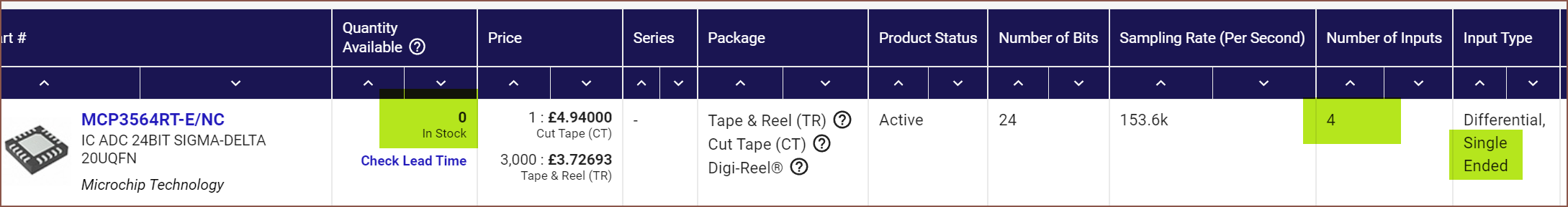
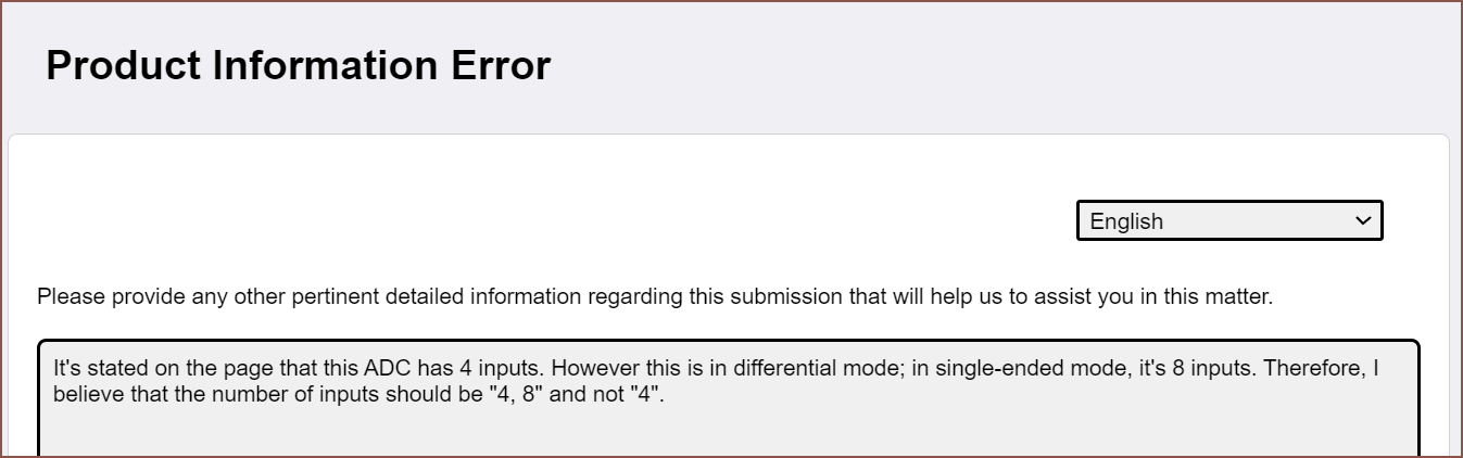
Back to ADCs, I found the reason why I wasn't finding the MCP3564R:
Even though Digikey says it has 4 inputs, it's actually "4, 8" inputs. I've reported it.
[11 Sep: I just got an email back saying they've fixed the whole series and should be reflected on the site shortly.]
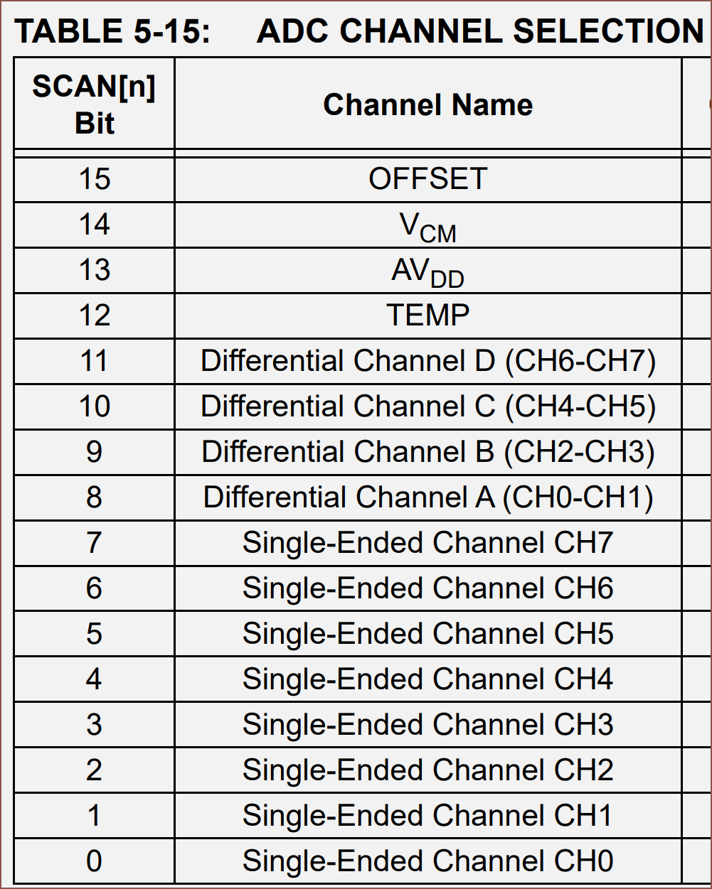
Anyway, the datasheet seems to imply that it's specifically designed to be able to multiplex through inputs without settling times. The ENOB values for 32 and 64 have also been omitted due to the 1-entire-bit reduction I mentioned.
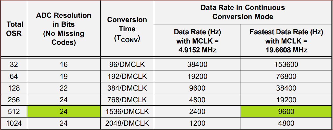
This chip has enough speed to sample 6 channels at 1600SPS whilst still allowing for a full 24 bits of resolution:
I think it would make sense to get 5 inputs at 1600SPS and then scan other inputs for diagnostics information, such as the solar cell voltage or ADC temperature.
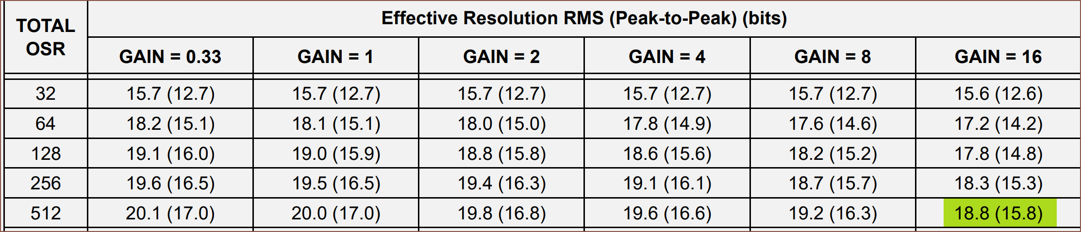
This chip allows for using 3.3V as the Vref or using an internal 2.4V source, though it seems that it's slightly better to use 3.3V:
I think their "peak-to-peak" value is equivalent to "noise-free bits".
The smallest FSR is 3.3/64 = 0.05156V = 51.56mV.
Obtainable resolution
With these options known, I can calculate the smallest force I should expect to measure without any noise.
It seems that any option I pick would be able to get 0.5 grams of precision. Yes, this doesn't sound anywhere near as good as the 0.1g precision scales, but remember that I need this data correct in fractions of a second, not an entire second.
Obviously, correct to the nearest 2 grams isn't going to work for a layout that is broken up into 8 gram layers, but if I can make do with 400SPS, I should expect to improve precision by over a magnitude. It is for this reason that -- PCB area permitting -- I'm probably going to go forward with the 32-Bit ADS1262 ADC.
Conclusion
This concept took 5 days to research and 6.75 hours to write out this log. The good news though is that Tetrinsic would now potentially be
more visually and dimensionally customizable (due to the 3D printed belt)
coggless
cheaper
self-sterilizing
more tolerant on finger misalignment (since it's now a wide 10mm belt instead of the valley created between 2 ball-chains)
more resilient to part sourcing issues
better in terms of active-length to footprint-length ratio
less software-complex since I don't need to communicate between 5 microcontrollers
lower power since I don't have 5 microcontrollers that need power
whilst addressing the concerns Me In The Past had about this solution strategy, such as ease-of-manufacture and electronic restoring force.
Voltage range: DC 8V-18V.
Speed: 5600RPM-12000RPM.
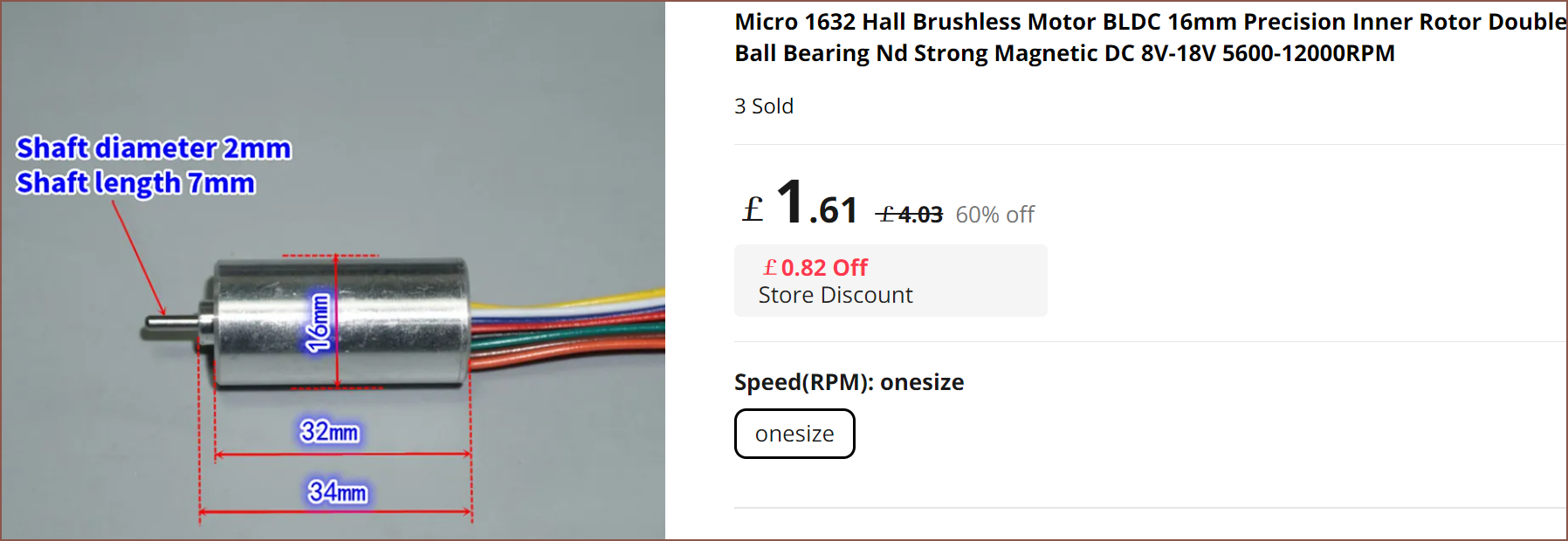
Motor length: 32mm.
Motor diameter: 16mm.
Shaft diameter: 2mm.
Shaft length: 7mm.
Weight: 23g
Precision 16mm brushless motor with inner rotor, body length 32mm, the appearance of the bulk motor is somewhat scratched by transportation, the motor is relatively good quality, all aluminum alloy shell CNC processing, motor front and rear ball bearings, built-in Hall-type brushless motor.
The rotor is composed of 4 rare earth neodymium magnets. The magnetic force is very strong. It is obvious that the reluctance of the motor shaft is rotated manually. This motor does not have a drive, so it needs an external brushless drive to run.
The motor should be nominally used at 12V, and the measured voltage can also be used between DC 8V-18V.
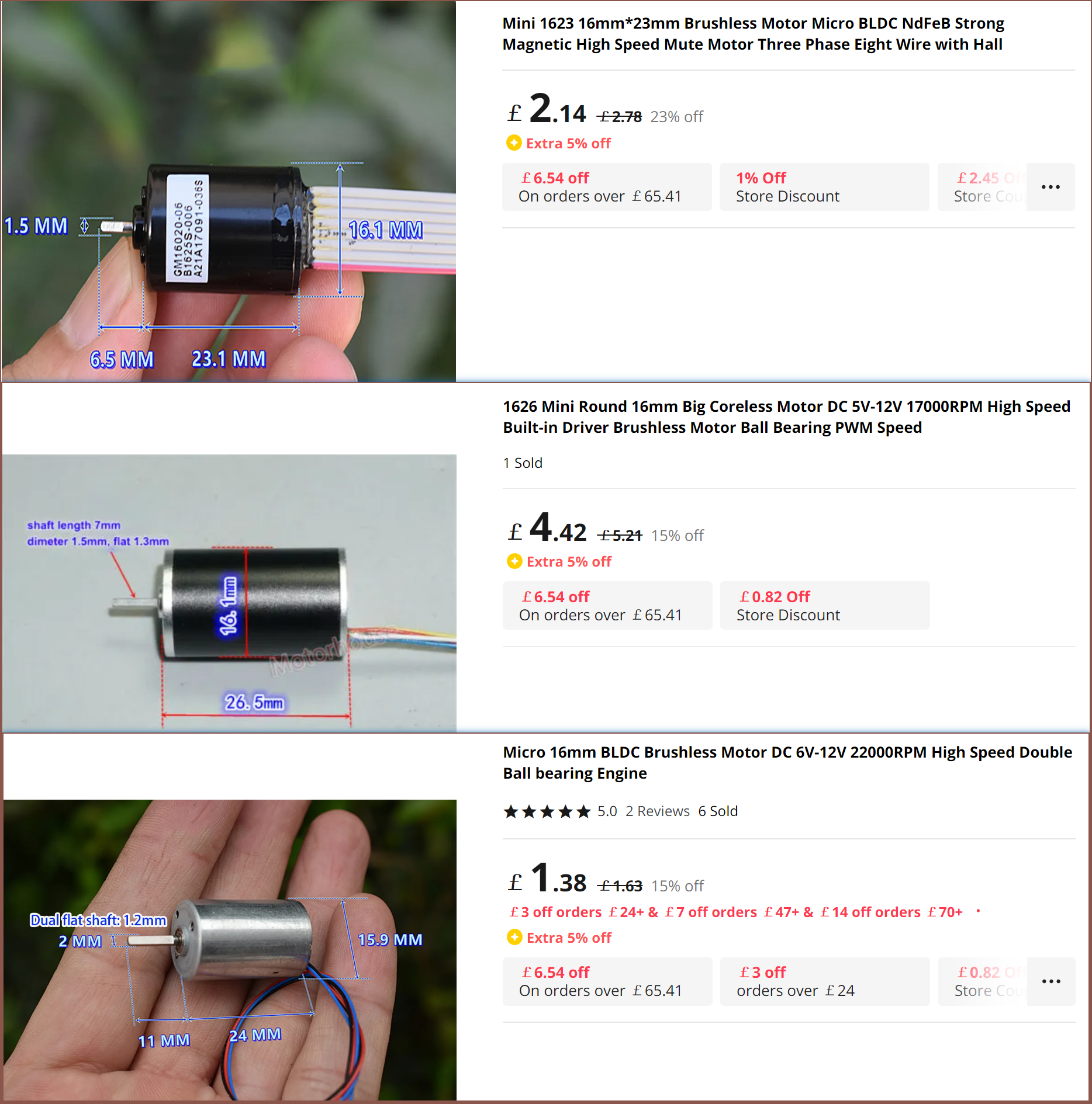
The RPM at 12V is 17% higher than the 580KV motor. The KV range of this inrunner motor is 700 - 667KV. It also sounds like the cogging torque of this motor is notable.
I then watched the following:
The summary:
Matching KV to the application is the most important
Generally, inrunners have a higher KV than outrunners
Inrunners can be more efficient as the windings can conduct heat through the case
Cogging happens in a slotted but not slotless motor [relevant video]
Cogging is stronger on a 6 pole motor.
Looking in the SmartKnob discord, it seems that for a device which is supposed to dynamically create it's own dedents, cogging is understandably not toleratable. This is what the creator means when he says that a motor has no cogging:
Even if that 1632 motor didn't sound like it had cogging so strong that the seller thought to mention it, I currently can't imagine a geometric configuration that I find acceptable.
Have you ever had that time when you're idly thinking and the thought "I should do something about that one thing before a problem arisises?". Well this morning I remember thinking
You know, if those motors go OOS (out of stock) like what happened with SmartKnob, it's game over, right? Like... just saying... we should finalise this design fast or even just buy 20 motors now.
before replying to my other self
They've been on the market for like over a year at this point. I think we're fine.
Well, I was scrolling though this lovely looking website of the Ratchet H1, which is the first commercial haptic knob I've seen, and was thinking "Ok, maybe I was a bit too hard on myself complaining that the £25-or-so Tetrinsics were too expensive, considering this is almost 6X the price."
Then I remembered that I hadn't updated the BOM spreadsheet since Concept3.2 over a month ago.
First item: LCD screens.
Me: Oh, that's no longer in here. Delete that row.
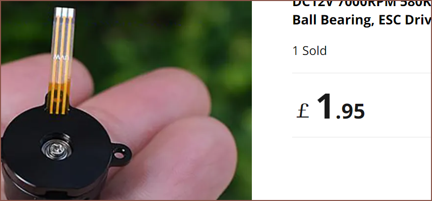
Second item: 580KV Motor.
Me: Oh yeah I better go check to see that the price is still the same.
First link: £1.95
Me: !
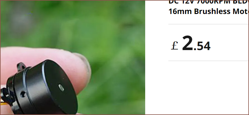
Second link: £2.54
Me: ! !
The message over the basket: Sorry, this item is no longer available!
Me: Starts scrolling my wishlist where I certainly saved the motor
The background music when I manually get to the bottom of the page, seeing nothing: Quiet and ominous [00:47s]
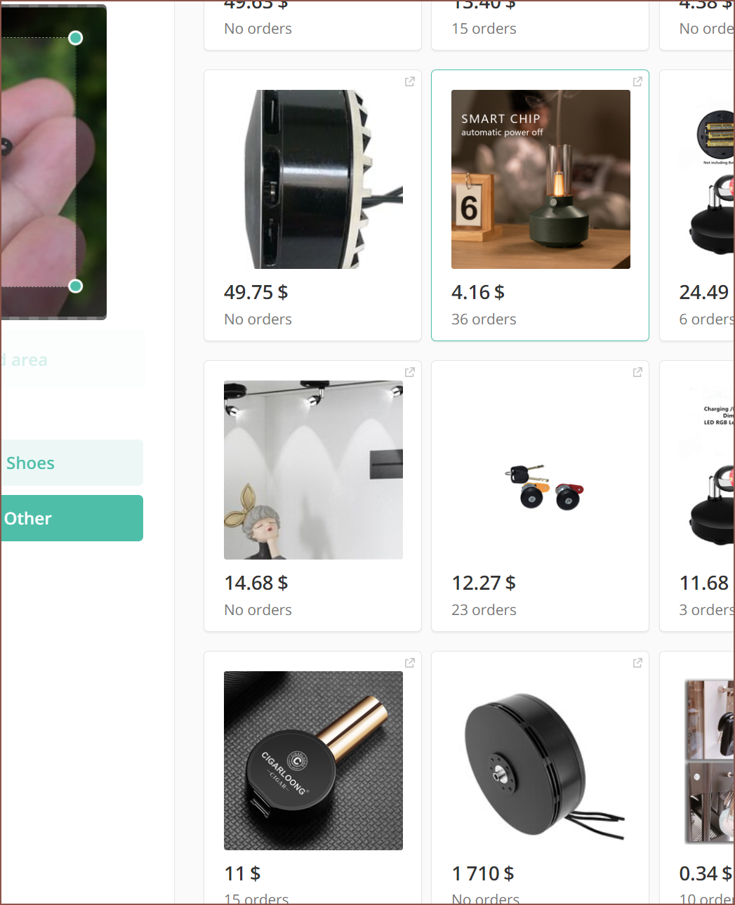
Vivaldi: 0 search results for "BLDC" or "580KV"
Bing: Shows 4 results, all of them wrong
Google: Links me to the £2.54 listing
Sigh. And just when I was feeling a bit excited with some "we are so back" energy. I was already kind of worried that these small motors were just old stock from something random. I've also read my fair share of products that have manufacturing or sourcing issues (like almost every hardware Kickstarter, Prusa, even Apple with the Vision Pro).
If the 580KV motors don't magically come back, or an alternative motor (I somehow missed every time I searched for it over the past 12 months) isn't discovered,
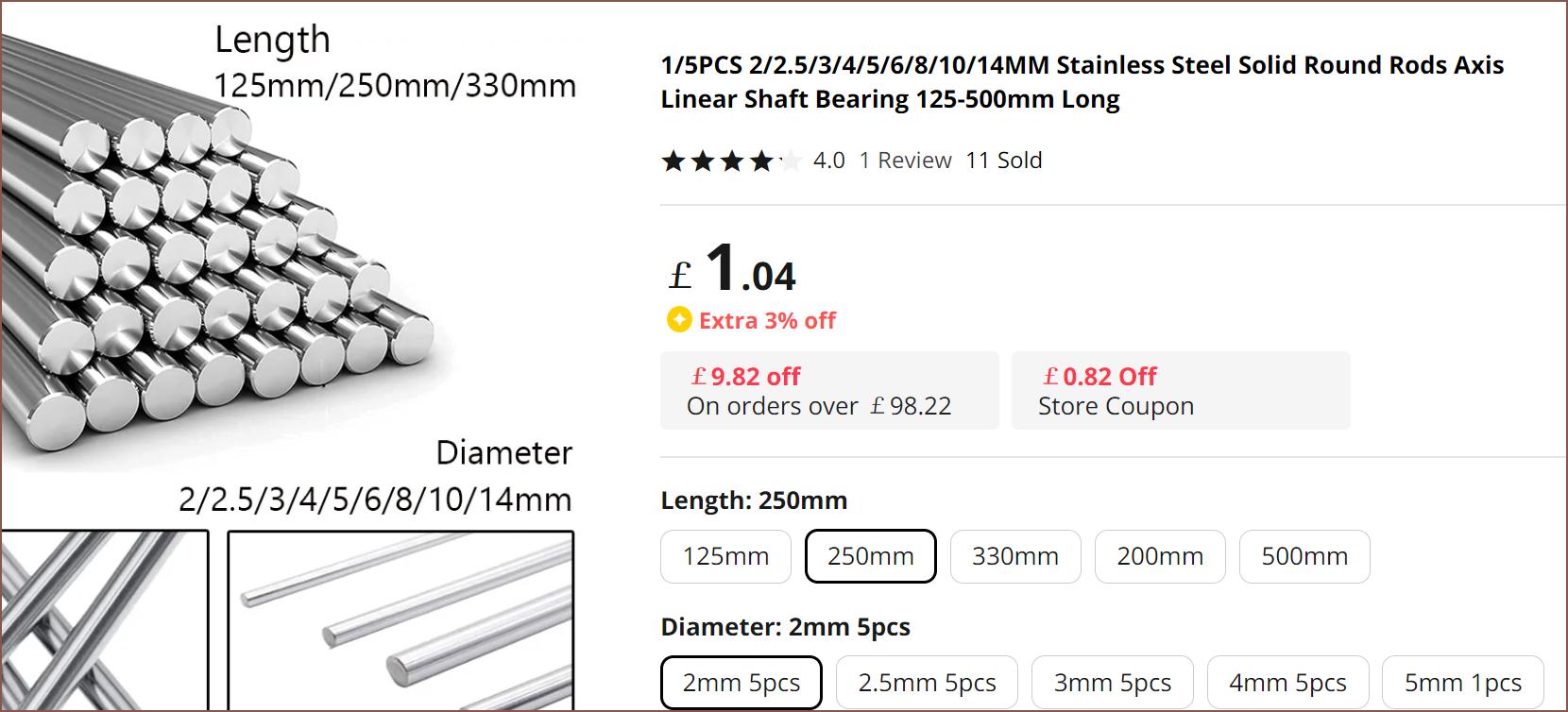
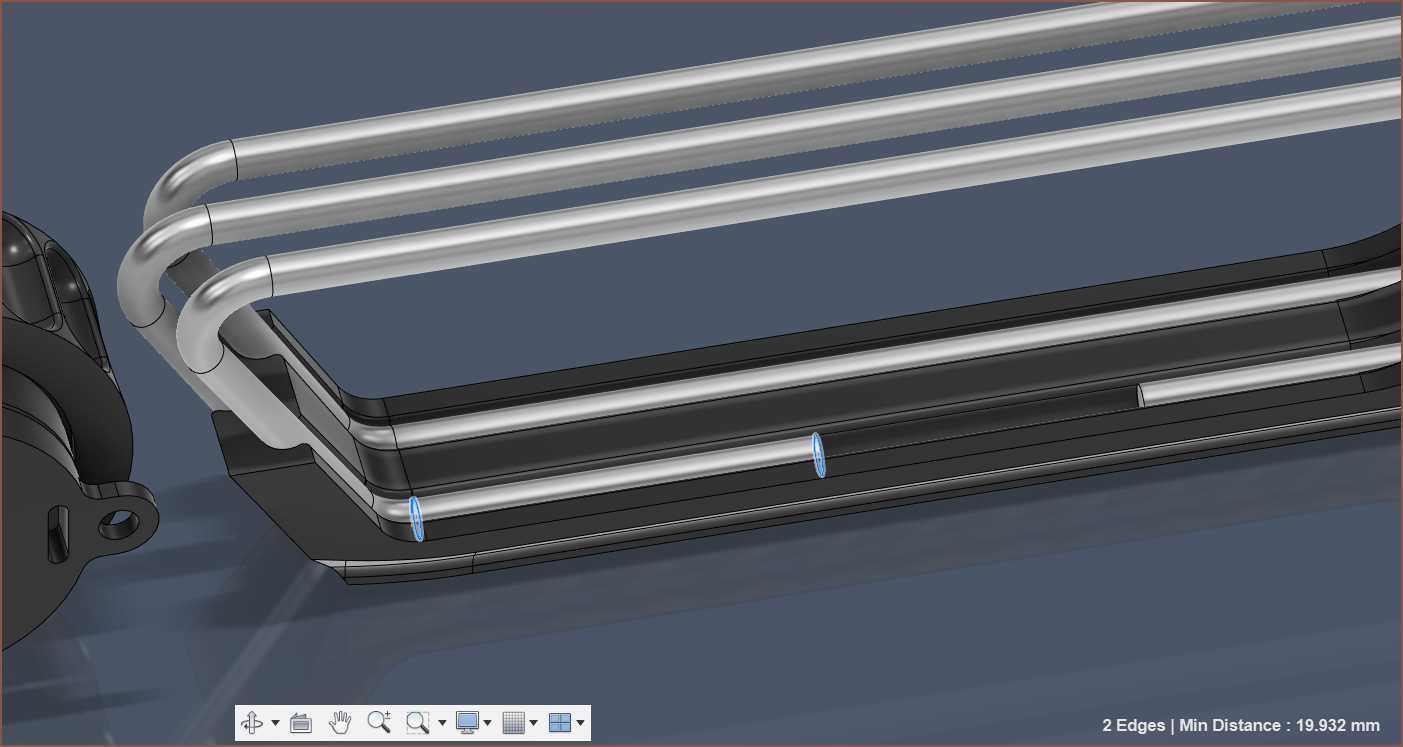
I first mentioned this in this Tetrescent log, but I've spent 3hrs modelling a new solution. The main reason being that most Aliexpress listings for stainless steel rods start at 2mm:
Secondly, even though one is probably never going to push down 500gf onto any Tetrinsic when in normal use (my thumb usually hits 420 - 450gf max and 300gf when not putting in the extra effort), the safety rating of 2.0 isn't ideal.
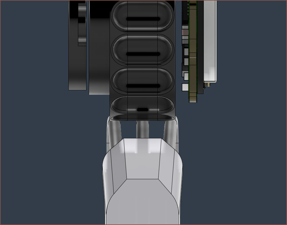
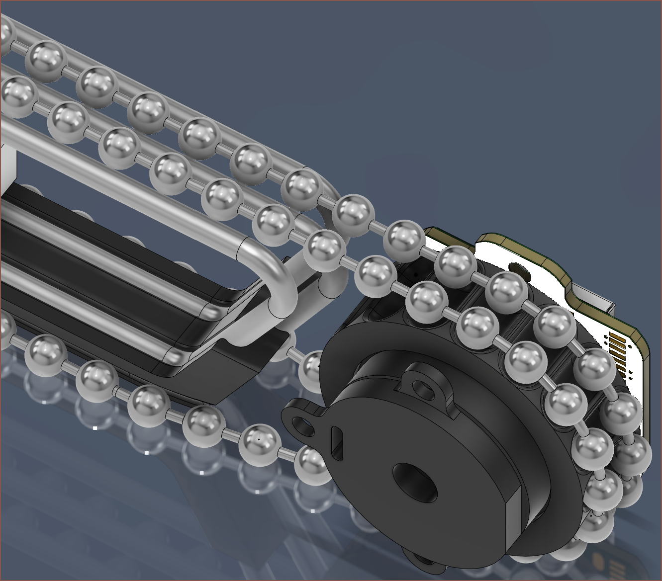
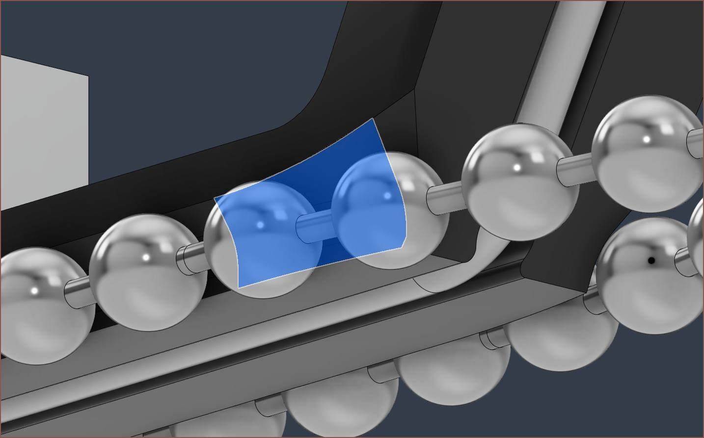
It turns out that the solution to the question "Should I have the rods go over or under the collector?" is actually "Both.":
This is to allow the collector to obtain minimum wall distances of 1.2mm whilst also allowing the ball chain to slide past. I've also added this smooth curve to ease the transition from air to the side of the pressure collector:
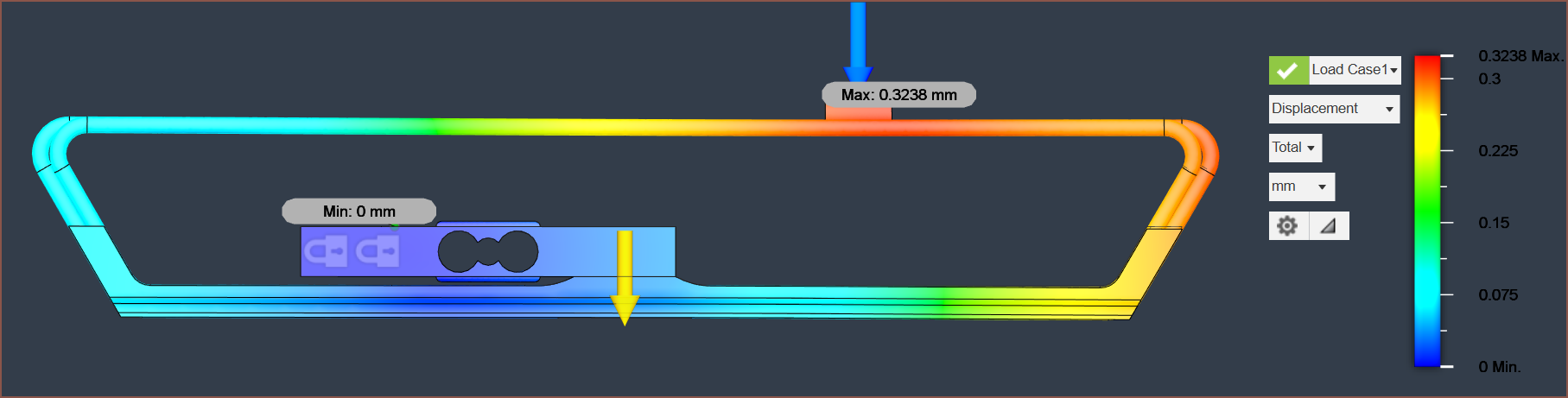
The new assembly has a much nicer looking displacement profile:
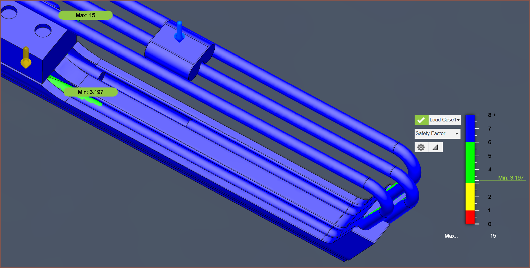
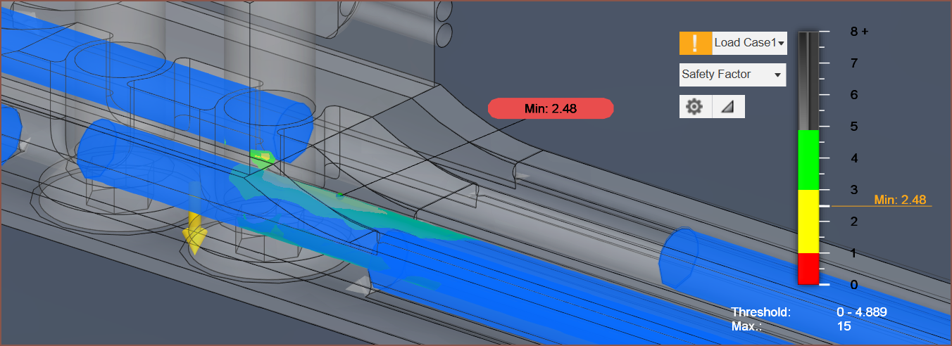
The minimum safety rating is over 3, but it's unexpectedly in the area just under the load cell:
Now that I've slept, this could be caused by the rod-ending offsets being too close together, meaning there isn't enough overlap where all 3 rods can bear the force. Increasing this offset to 27mm (from 20mm) reduces displacement to 0.300mm (from 0.324) and increases the safety factor to 3.78 (from 3.20). Reducing it to 10 increases displacement to 0.359mm and reduces the safety to 2.78:
I'll go with a 29mm offset to leave about 20mm from the last bend:
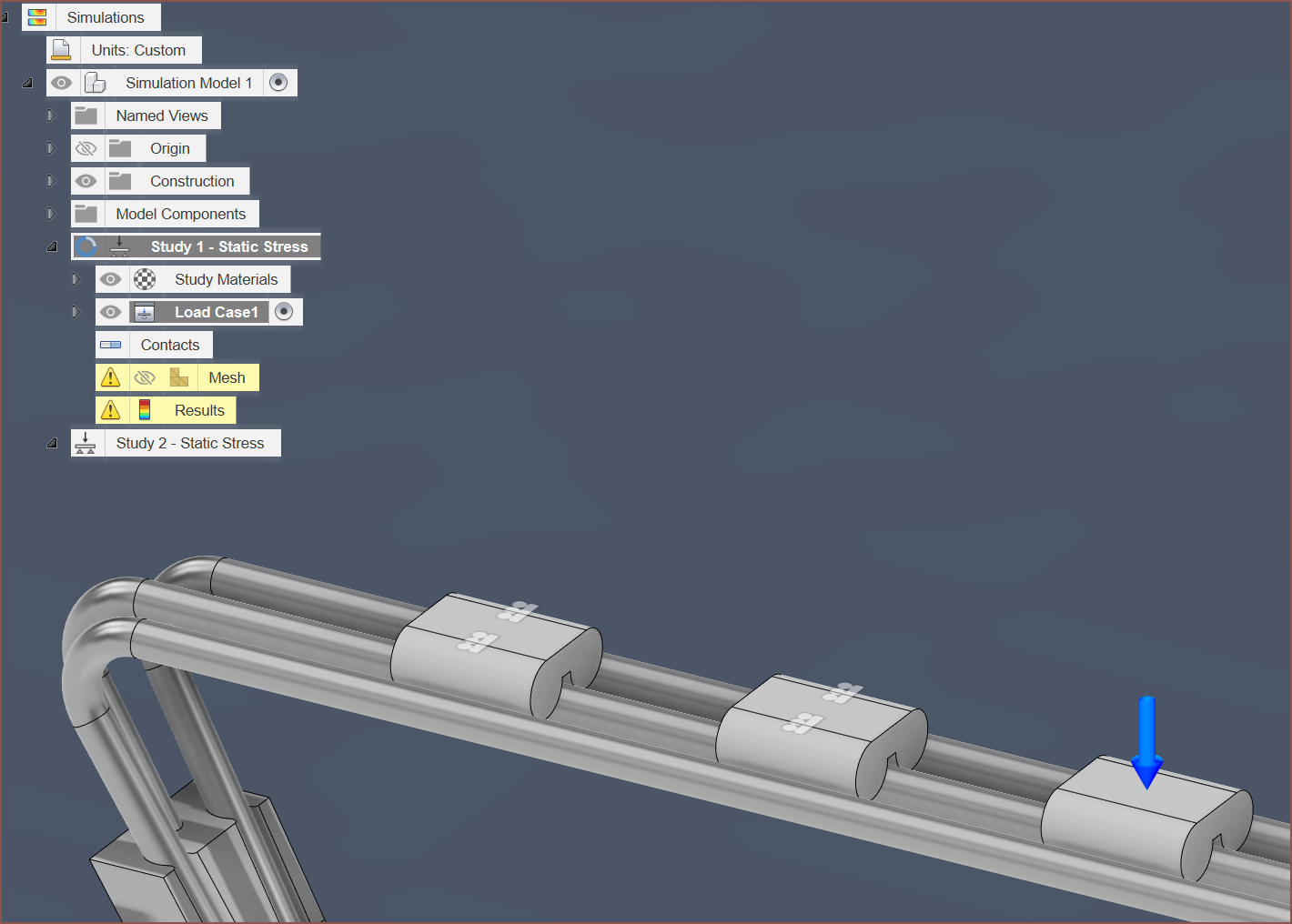
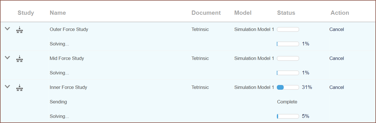
I'm now trying to see if I can actually obtain simulations for multiple force points by making the ones that have no force applied "frictionless":
No, that failed:
I'll just have the forces without the "frictionless" constraint. I'll assume that the extra bodies have a negligible weight.
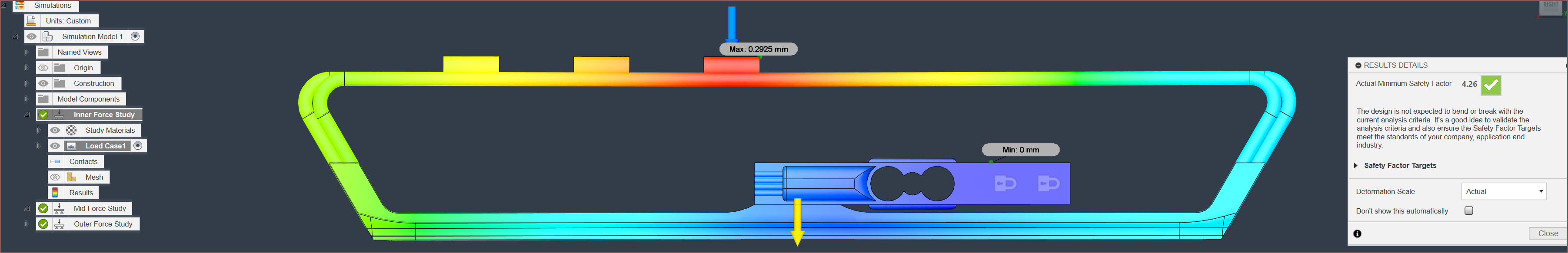
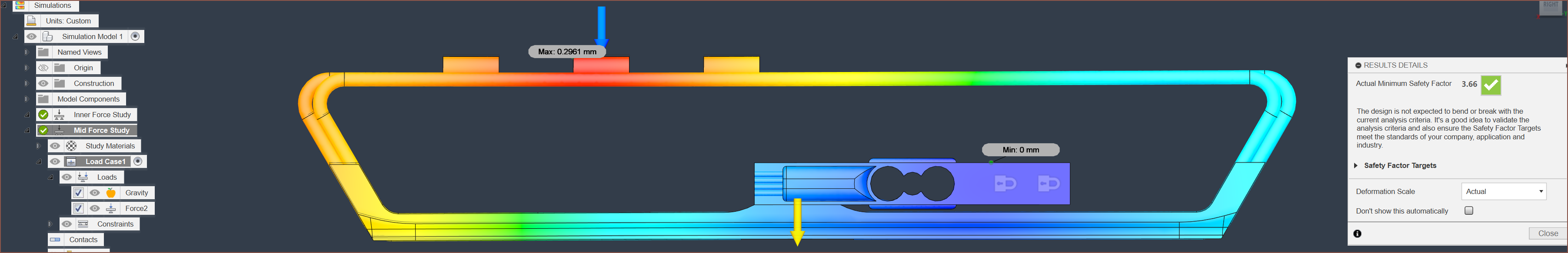
It seems that Fusion does each solve sequentially. At least that means I could be inspecting one study while another one solves on the cloud. Anyway, here are the results:
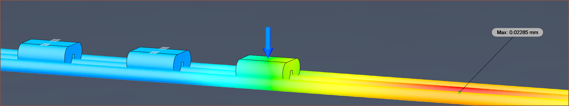
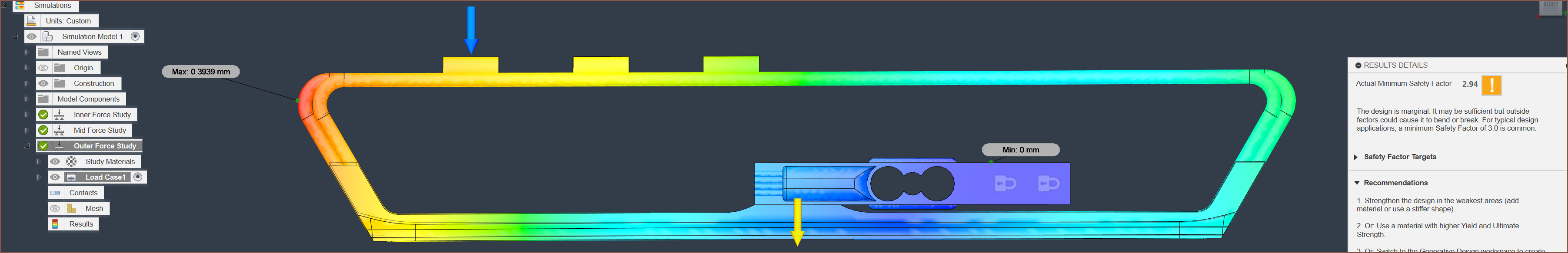
I've set the displacement to "Actual" above, but to better see what's happening on a micron level, "Adjusted" is below:
It seems that the "minimum of minimum safety factors" is 2.94, when the force is applied near the ends of Tetrinsic. The outer force position has a max displacement is only 0.35mm, so it should feel rather solid throughout, even when pushing down at 500gf.
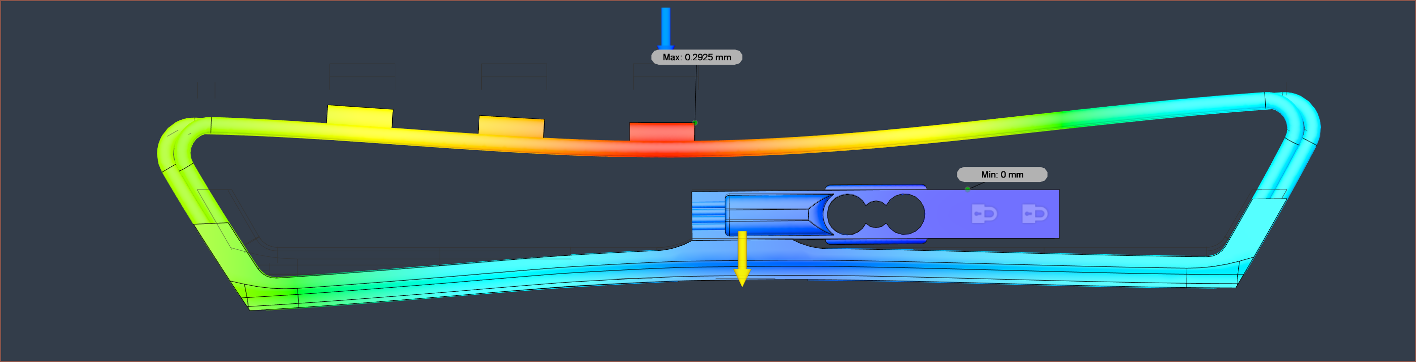
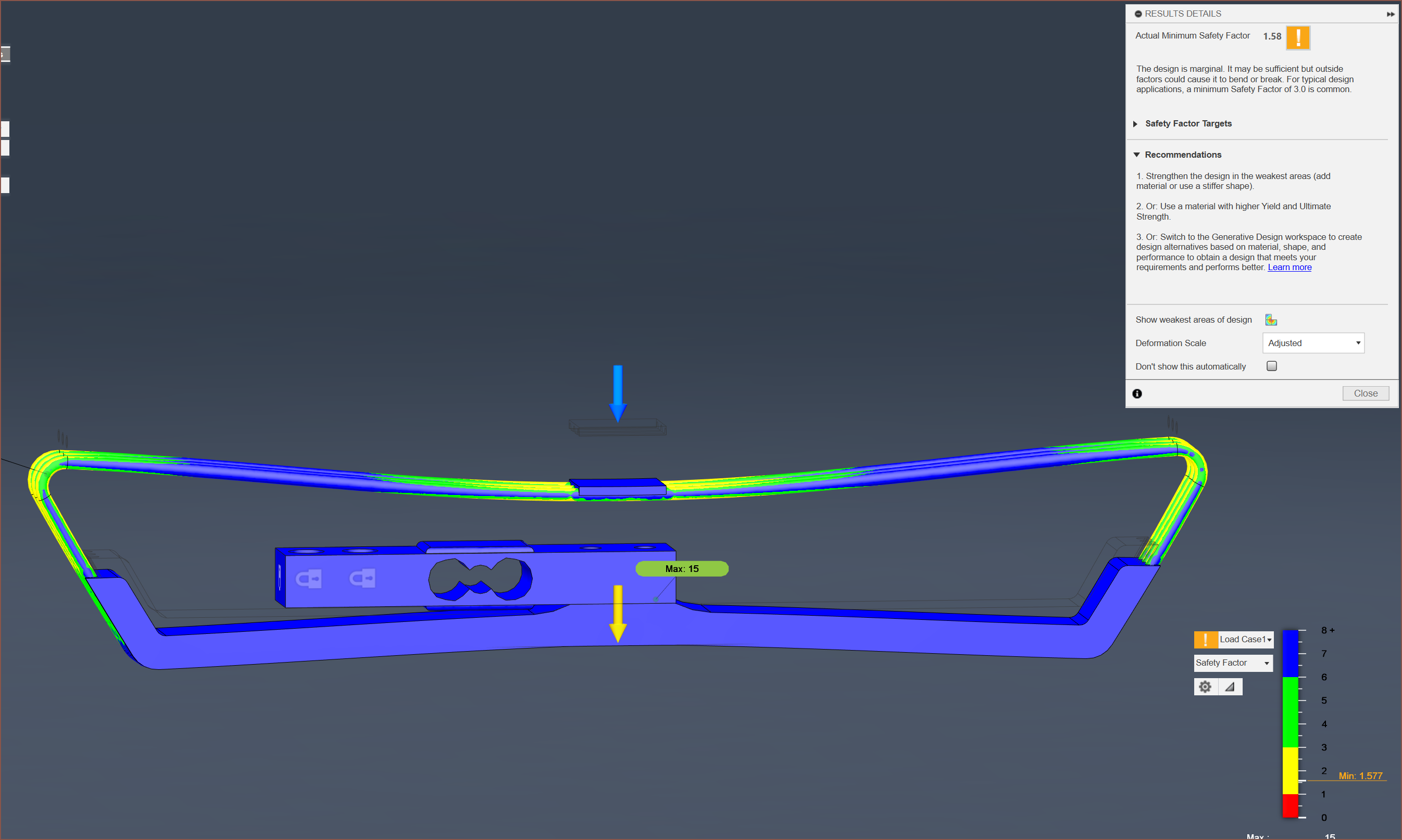
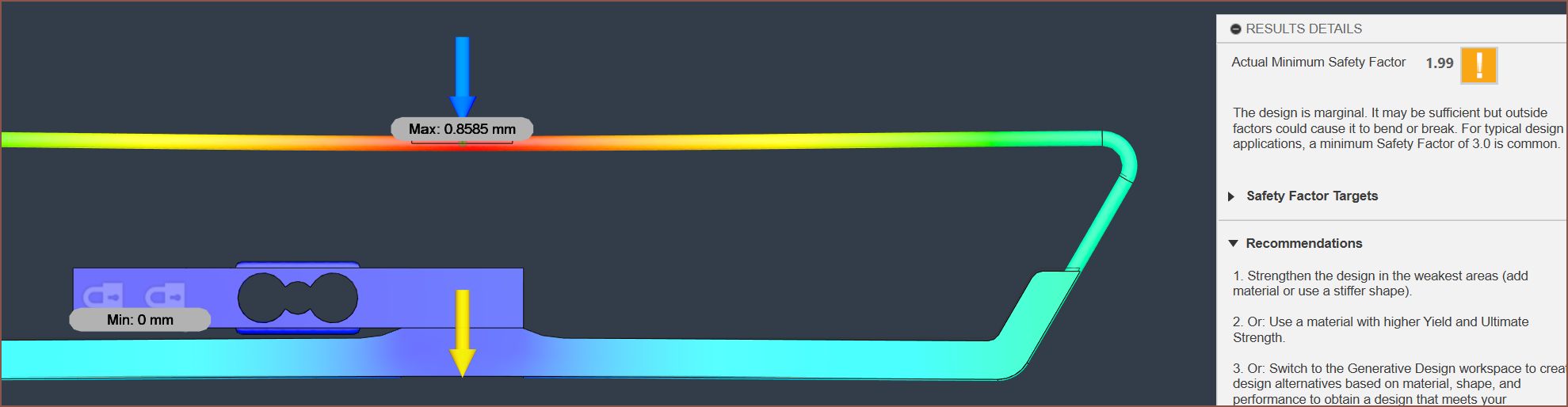
So I'm considering a 125mm solar cell for Tetent, and since this is much longer than my initial assumtion of a 75mm Tetrinsic, I thought I'd actually get a simulation.
I've modelled the tubes with a 60 degree inwards bend (instead of a 90 degree straight-down bend) so that the ball chain can take a shallower angle from the sprocket to the sides of the "pressure collector" as I call it.
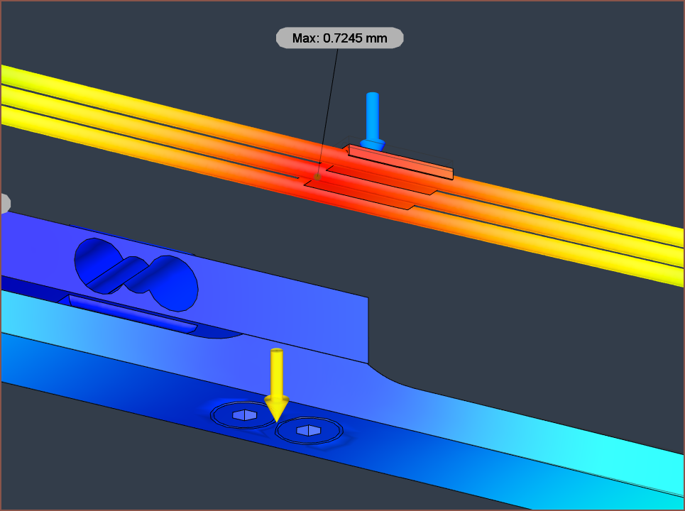
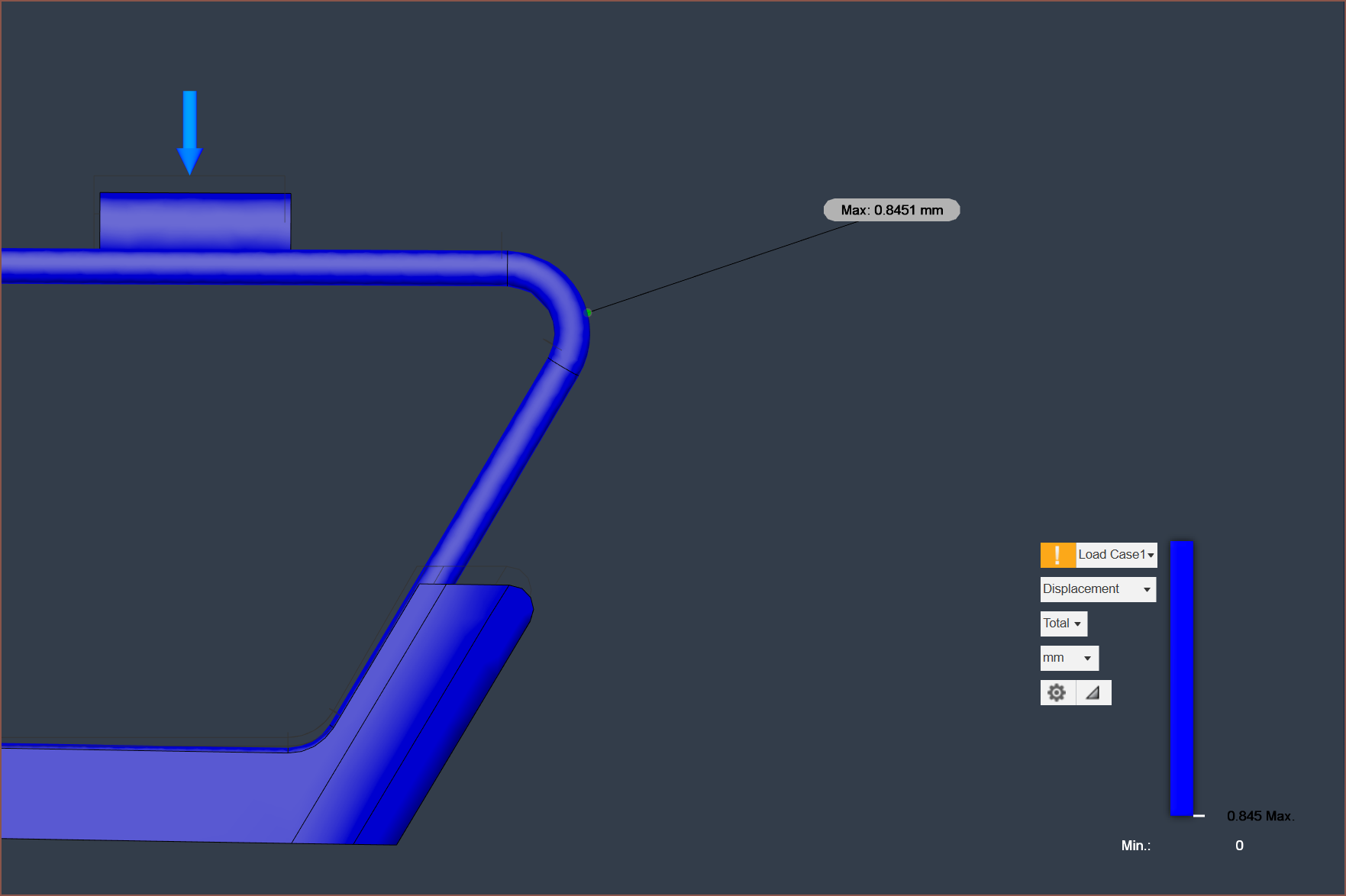
I've got a 500gf load exerted from the middle of the area, and it's already not looking so good, acheiving a minimum safety factor under 2. The good news is that, as expected, the load cell has almost no displacement, meaning that the force sensing area is symmetrical when under load.
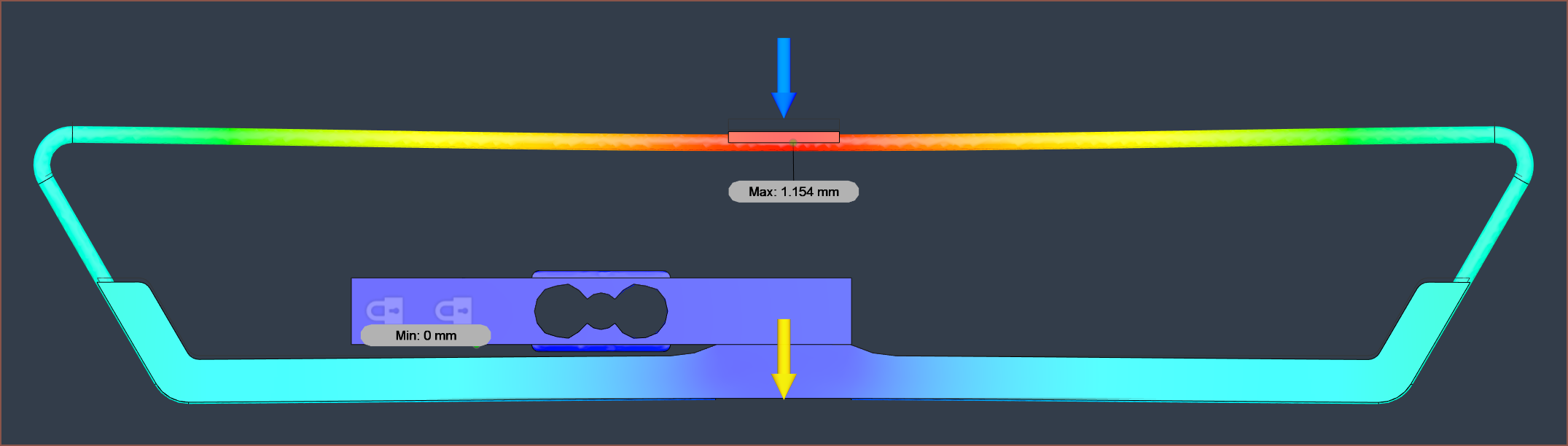
The displacement is rather high, at 1.15mm. My goal is to cut that in half somehow.
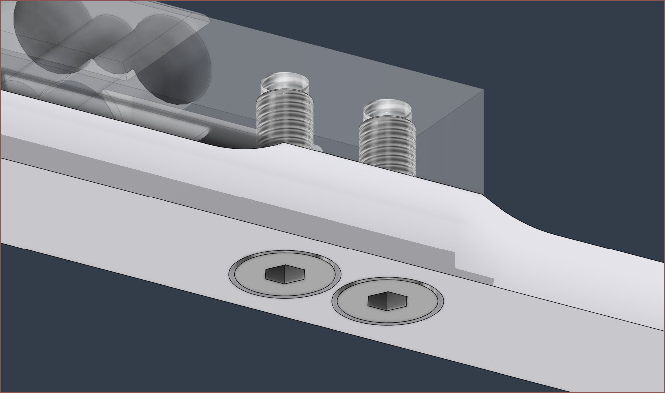
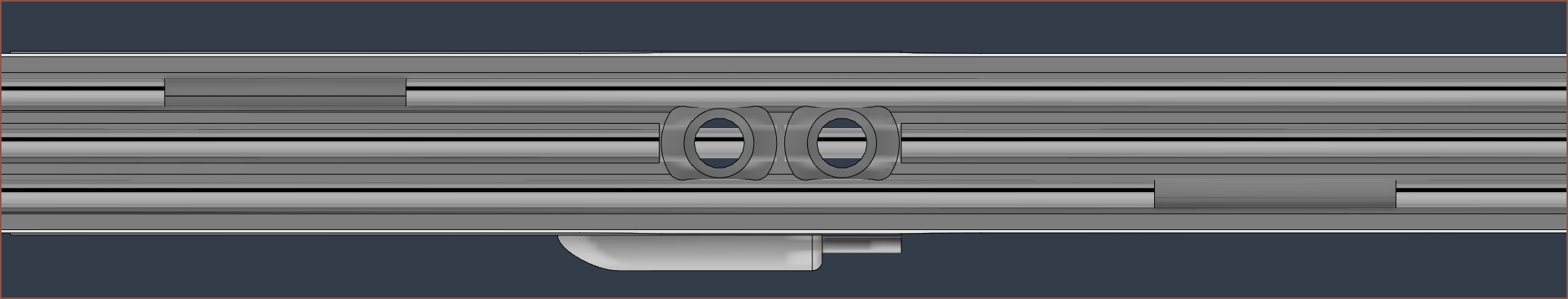
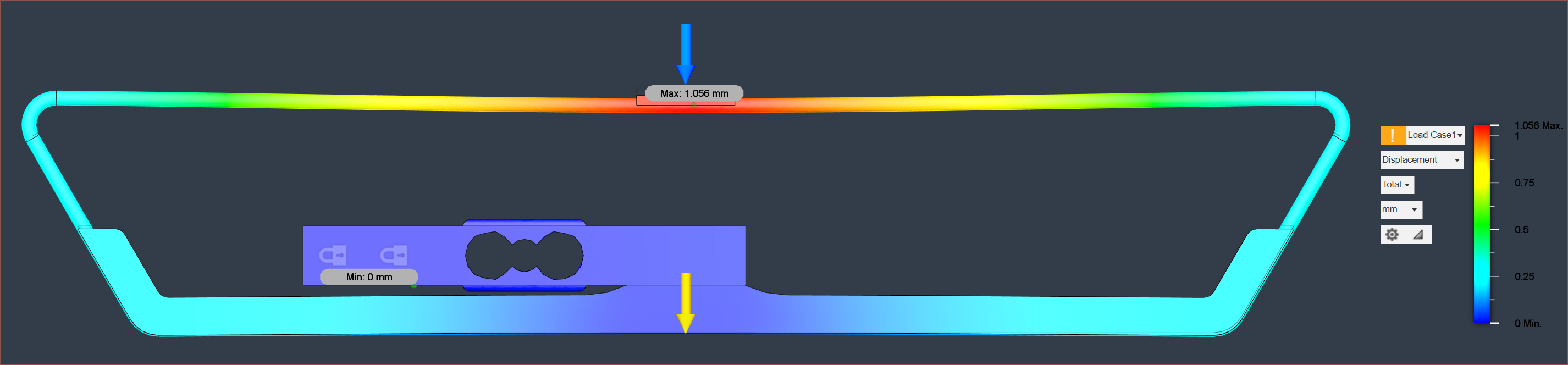
This is where the outer tubes have their cutout not in the centre, which aims to have at least 2 tubes providing stiffness across the entire collector. I planned to do this on the 90mm Tetrinsic, but there wasn't enough length on the ends (only 5mm) before it needed to bend. Even still, this solution would be geometrically invalid since the tubes would intersect the countersunk screws.
Unfortunately, the displacement only improves by 0.1mm and the safety factor is unchanged.
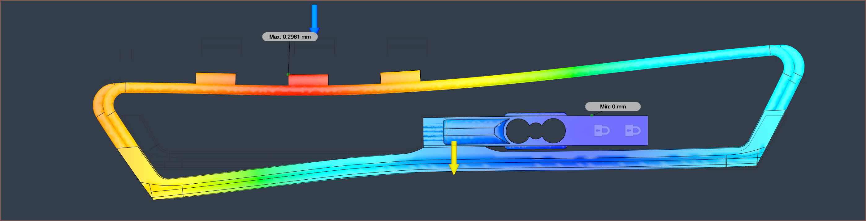
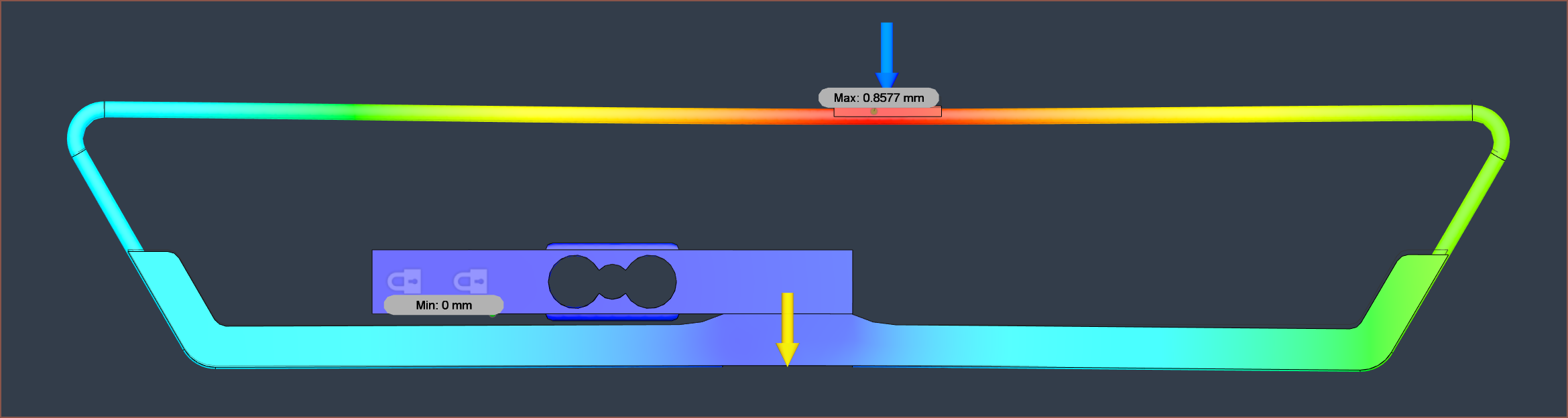
Returning to the aligned-end tubes and having them made from solid steel (so they're more like 1.5mm thick wires), I get a displacement of 0.86mm and a safety factor of 2.
Interestingly, the displacement is still 0.86mm when the force is applied directly under another Tetrinsic, but the right side is greener than the left side. Green means over 0.4mm of displacement.
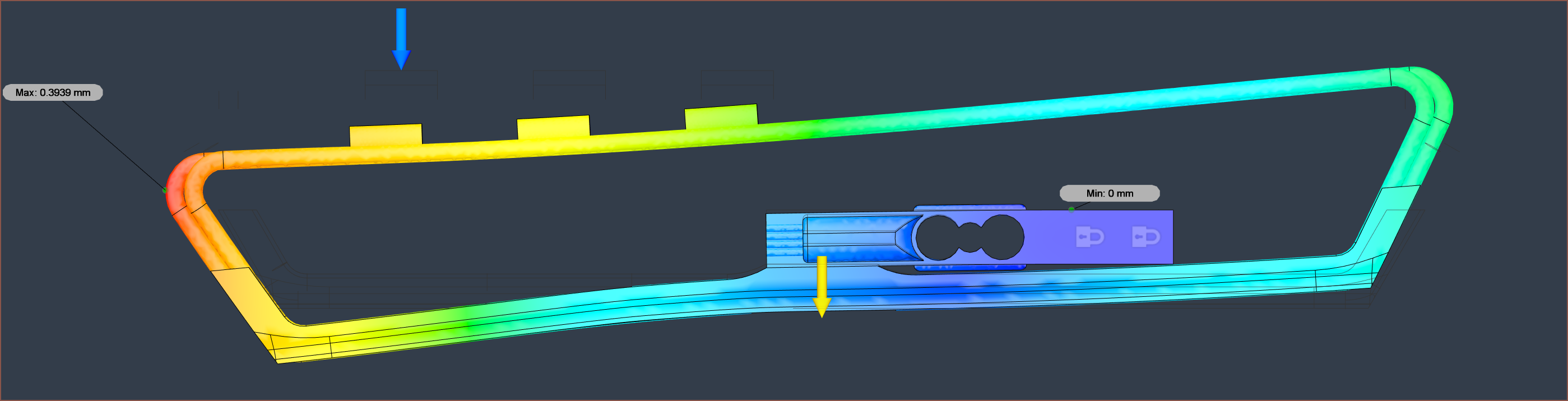
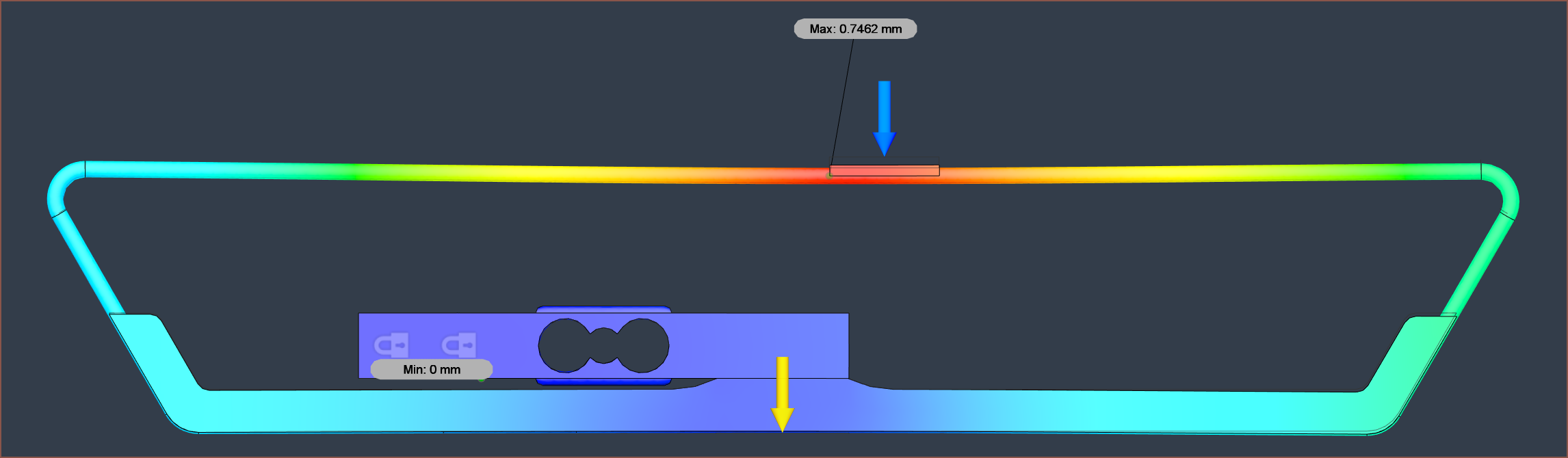
The displacement is more balanced with the uncentered cutouts. I probably should go with the other solution, whereby the collector is on the "outside" of the loop.
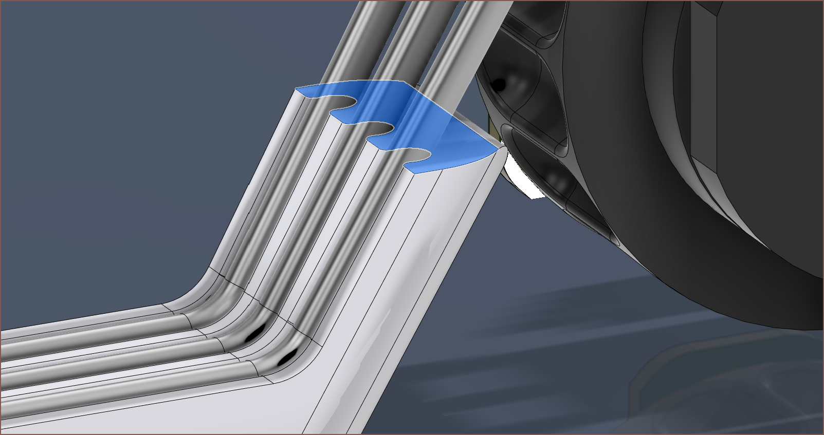
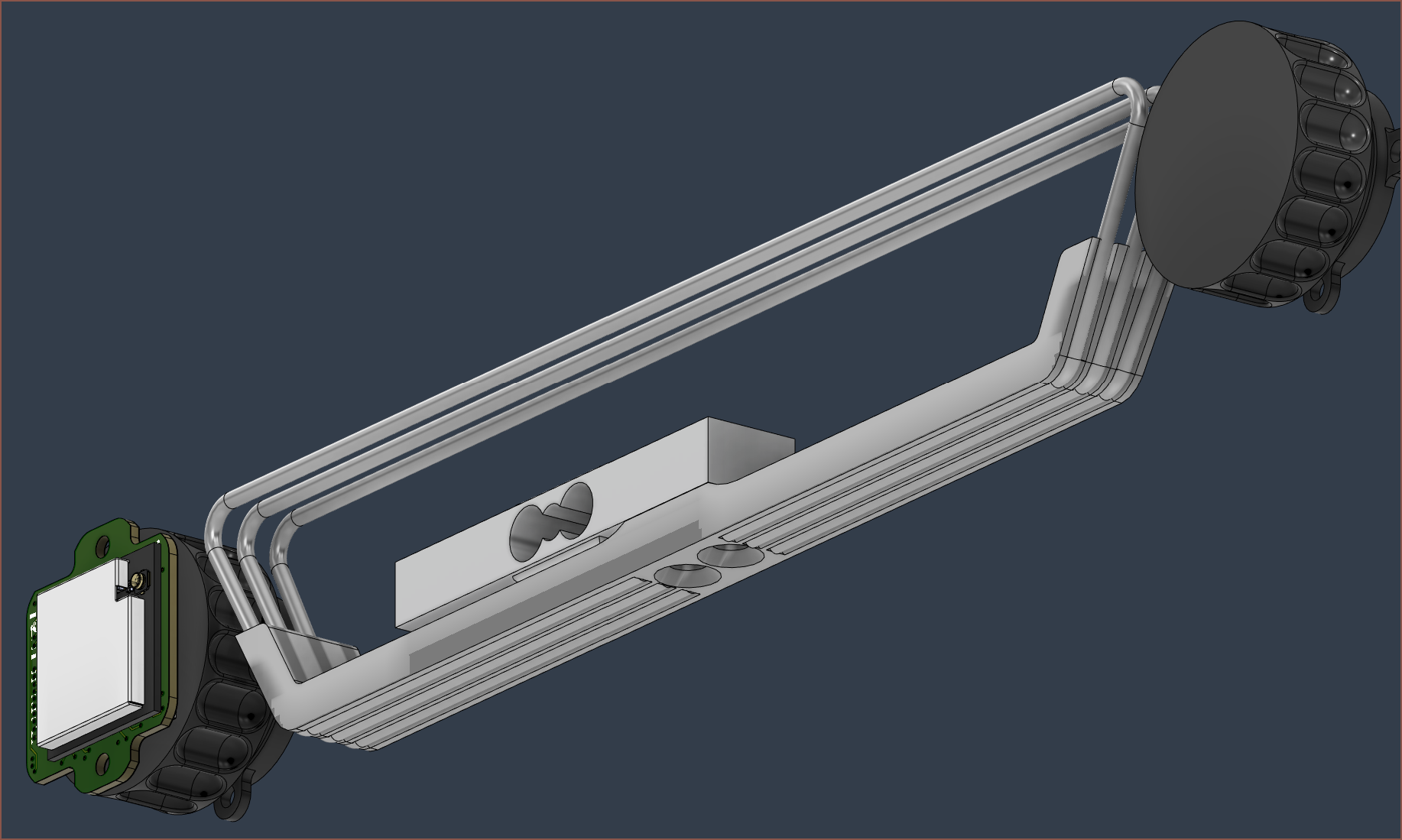
So this is it. It certainly looks more complex. The main benefit of this strategy is that the finger force pushes the tubes further into the collector, instead of pushing the tubes out of it.
The main drawback is that the ball chain will have to slide over plastic to be moved out of the way. At least, that was the drawback I thought of when comparing the two strategies before I started modelling. Due to the way I designed the first collector, the ball-chain would still rub against plastic.
Another benefit is that, similar to a boat through water, I can print a seperator that splits the dual chain.
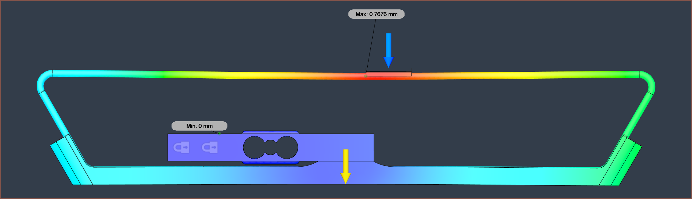
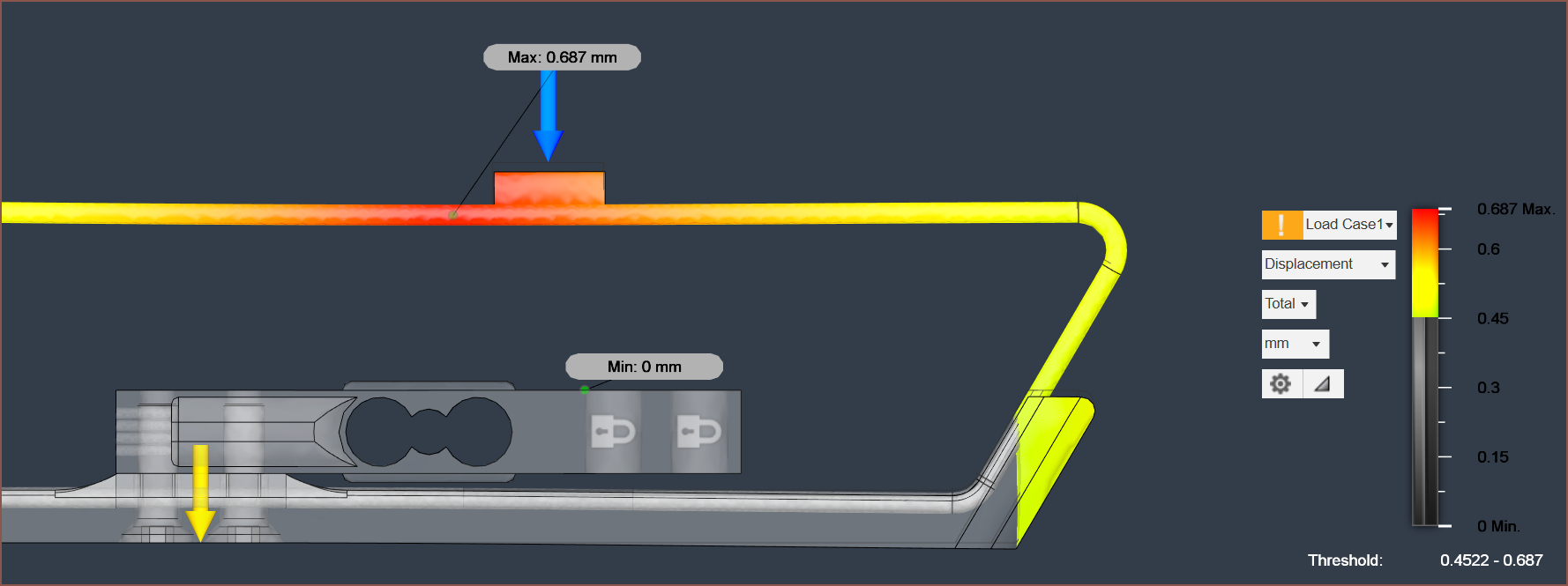
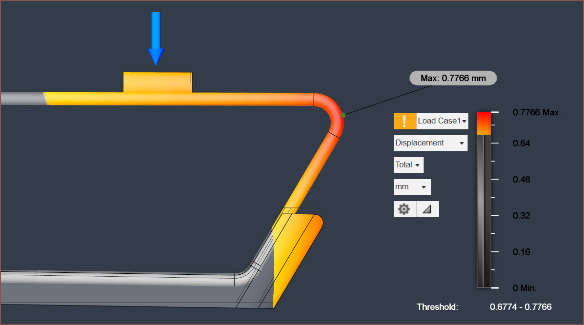
With this, I get a max displacement of 0.77mm and the base has a displacement of 0.34mm.
Considering print orientation, it's probably best if this face was horizontal instead of perpendicular to the tubes.
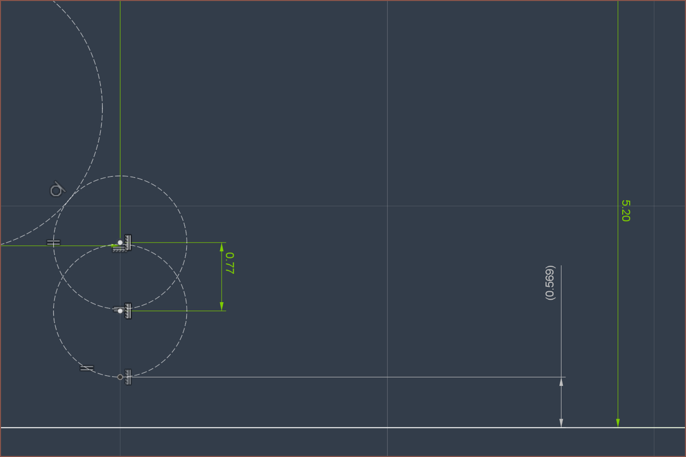
it seems that a height offset of 5.2 - 5.5mm would be required:
As will M3x10 countersunk screws:
So these bolts were actually causing the simulation to fail until I did a combine-cut to eliminate the geometric intersection between them and the load cell.
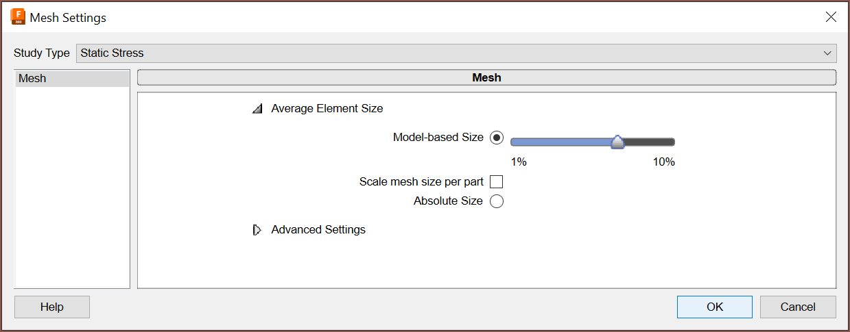
Now, for some reason, trying to simulate forces from distances over the 9.3mm set in the above simulation caused the simulation to fail. I tried a few different things and red the error logs, and I've been able to get a 25mm force sim to succeed by reducing the mesh setting to around 7%:
I simulated 50mm, and for some reason, only the "Displacement" view is glitched:
45mm worked though:
It does seem that I should also have a 0.75mm spacing below Tetrinsic to allow for this part to flex uninterrupted.
 kelvinA
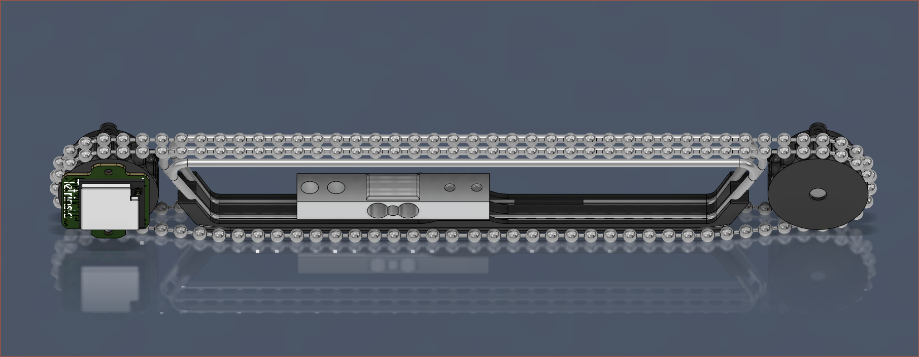

 Then I needed another run. I decided to go with a quote this time, and despite it being 5am without having slept yet, I managed to 100-accuracy it.
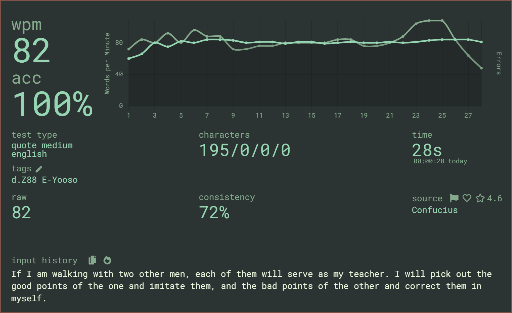
 As you can see, there is no movement of the finger and only 2 force levels were needed to input the quote. Perhaps that's actually the strat to understanding the data: looking at individual fingers instead of all of them at once.
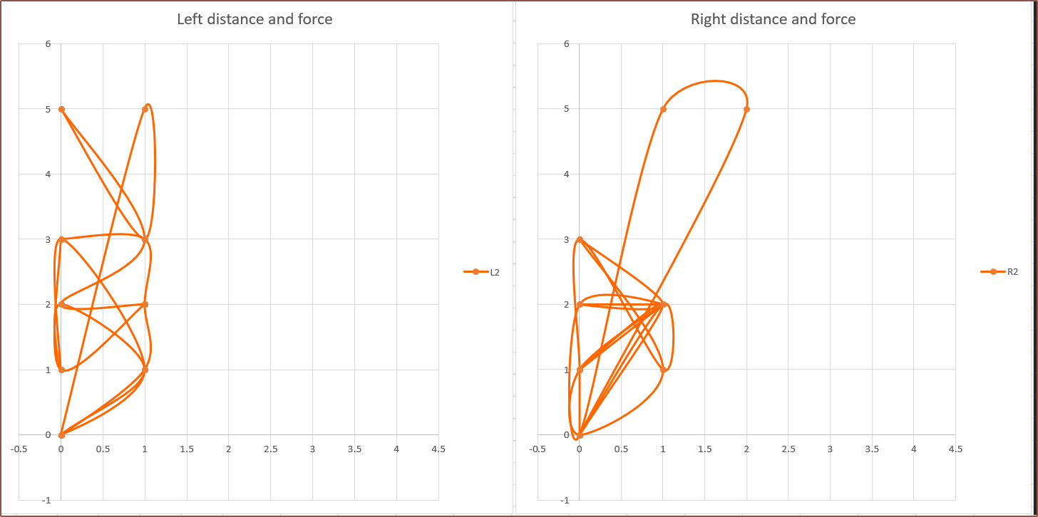 Finger2 is looking very promising, especially the right finger where most of the action is in the lower left corner. In contrast, Fingers 3 and 4 are looking less optimal, with 4 slightly worse overall:
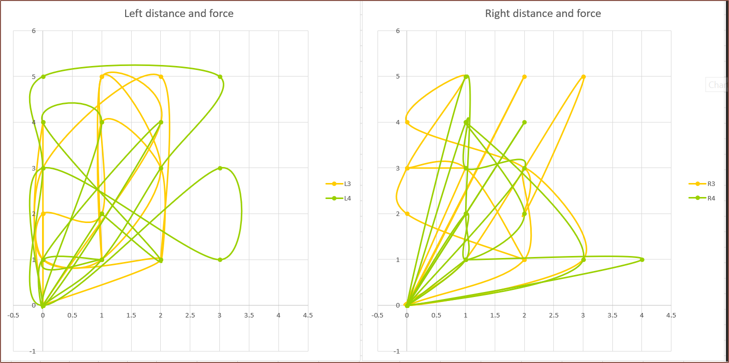


 The displacement is more balanced with the uncentered cutouts. I probably should go with the other solution, whereby the collector is on the "outside" of the loop.
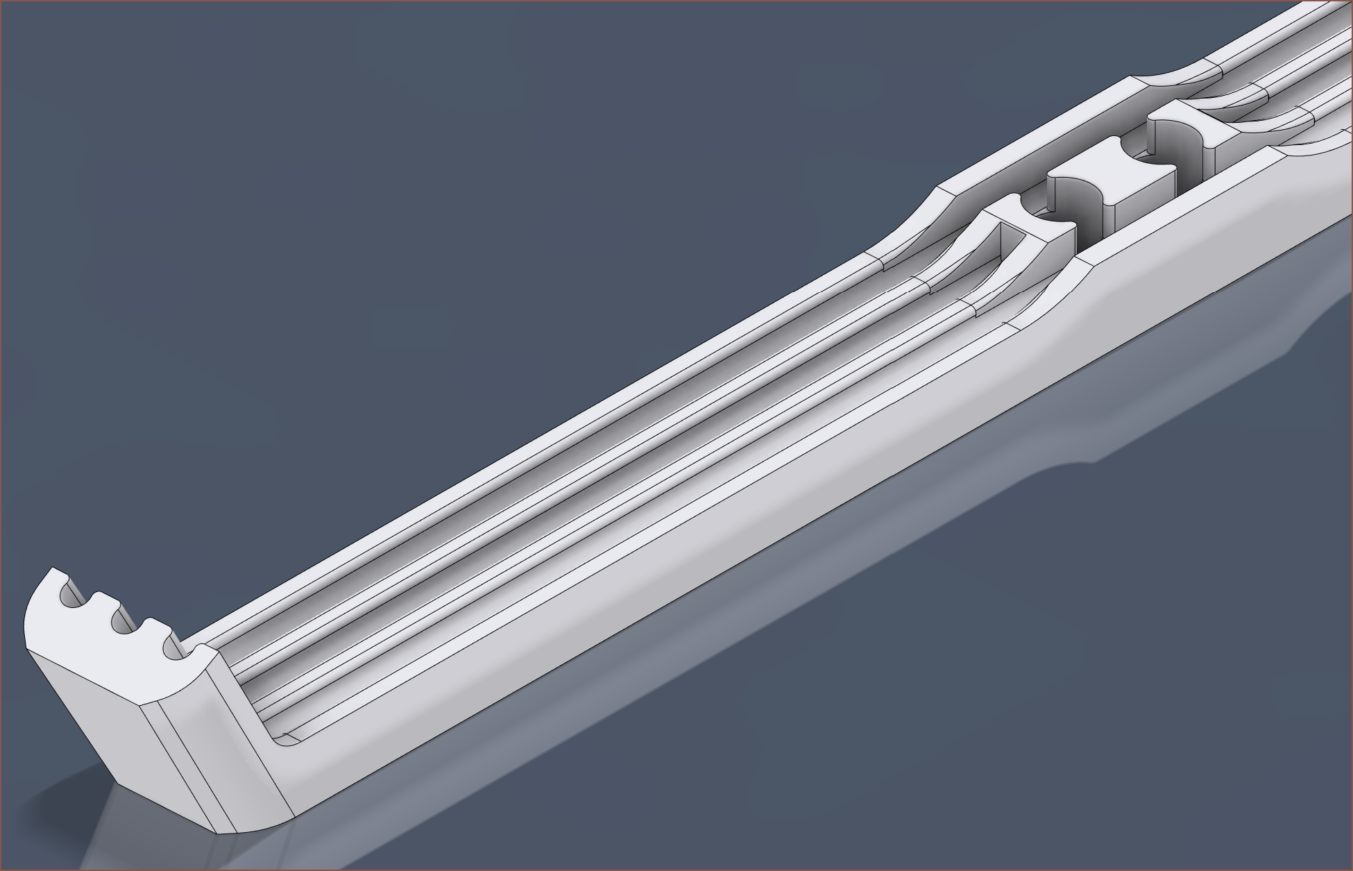 So this is it. It certainly looks more complex. The main benefit of this strategy is that the finger force pushes the tubes further into the collector, instead of pushing the tubes out of it.