Emilio P.G. Ficara
125KHz tag reader and contactless lock
The circuit, based on micro ATtiny2313, reads RFID tags at 125 KHz. The code of the first tag read after programming the micro is stored in the internal earom and subsequently produces a pulse of about one second on the relay contacts each time the tag is positioned near the reader. This allows you to create a simple contactless electronic lock.
The stored tag (and any other tag that is placed near the reader) also causes the serial output of the internal code, in ASCII format, which allows to implement a generic reader for access control.
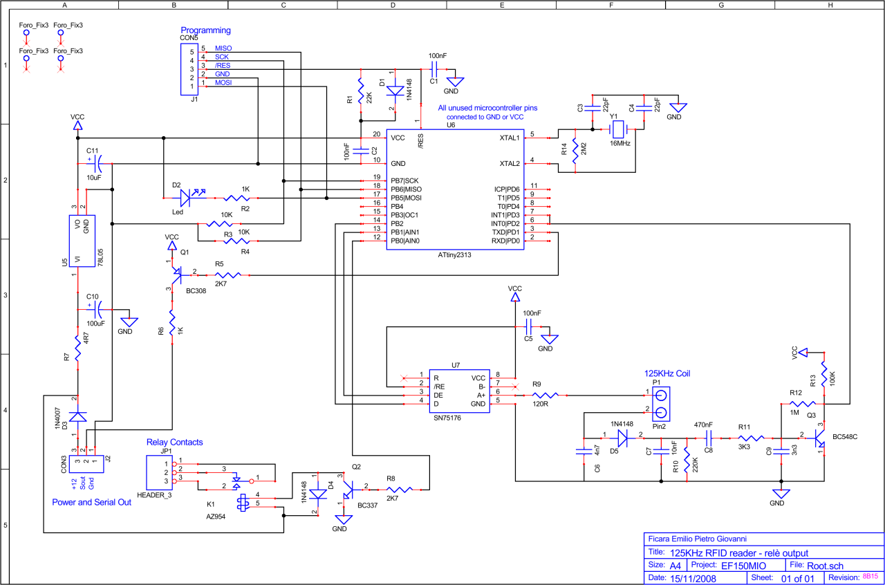
This circuit was published by me in the CQ Elettronica magazine in the May 2009 issue and entitled: “125KHz RFID reader”. More details on the circuit and implementation can be found in the article. Below, the wiring diagram:
For burning the micro, I used the freeware SP12, in the versions for WinXP or Win2K. The batch files included in the downloadable ZIP require the use of this software for programming the micro (you can easily find it with a search). If you have another tool for programming the micro, the configuration for the fuses in the described application is as follows:

The downloadable file ef150-hackaday.zip (with password: eficara) contains:
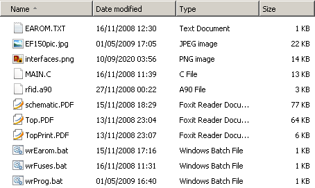
- MAIN.C - the C source
- schematic.PDF - the wiring diagram in PDF format
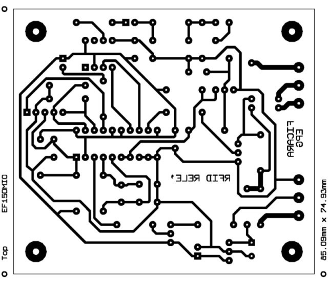
- Top.PDF - the PCB layout (single side) in PDF scale 1:1 (see below)
- TopPrint.PDF - the components layout
- rfid.a90 - the compiled HEX file ready to program the micro
- wrFuses.bat - the batch file to program fuses
- wrProg.bat - the batch file to program firmware
- wrEarom.bat - the batch file to overwrite the earom (delete the stored tag)
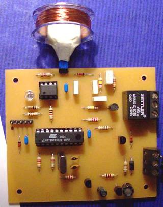
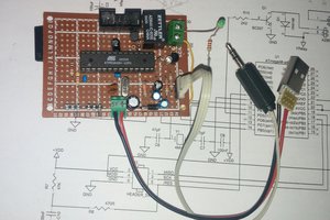
- EF150pic.jpg - a photo of the assembled circuit
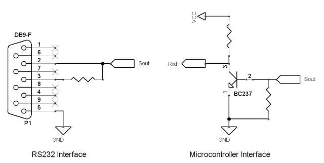
- interfaces.png - a couple of circuits to interface the card to a PC or to a micro (see below)
- EAROM.TXT - the text file containing the 5 bytes to clear the key tag in earom
The following notes are taken from the readers' comments on my old website.
Added Aug 30, 2009 The coil has 105 turns of 0.2mm wire wound on a 30mm diameter support; in the prototype I used the neck of a plastic bottle, visible in the figure.
Added Feb 28, 2010 Note: The SN75176 driver is used as a power driver ONLY, but the circuit works even if you remove the chip and simply put a jumper between pins 4 and 6 of the 8-pin socket. Obviously, the driver makes the PB2 output pin of the microcontroller more “relaxed”.
Added
March 1, 2010
Note: You can browse the AVR SP12
programmer project at this site / url:
http://www.xs4all.nl/~sbolt/e-spider_prog.html -- mmh, I tried now (July 30 2022) and unfortunately the site has not set the permission to access it as http. Try an internet search or use another tool, sorry
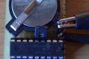
Added March 2, 2010 Oops, someone noticed that the photo of the circuit shows an ATTiny2313V-10PU cpu; well, the right chip is the one found in the circuit diagram: the ATTiny2313-20PU. The latter, in fact, can work with the 16 MHz crystal necessary for the application, while the former is only guaranteed up to 10 MHz. The reason for the 10 MHz version mounted on board is (simply) that not having the fast version, I tried (successfully) the slow one. Ok, don't look at the photo, look at the diagram!
Added April 14, 2010 Note: I have received many requests for the C or Assembler source for this program and have decided to make it available! It is located in the zipped file; the compiler used is the IAR Embedded Workbench KickStart Edition
Added on 10 September 2010 The action range is about 3 cm with the coil shown in the picture. Better results can be obtained by changing the diameter of the coil (and the number of turns, of course).
Have fun!

 Nick Bild