 Nikola Manolov
Schematic Description

The schematic for this project is quite simple.
There are two USB connectors. USB A - for a connection to the device under test and USB B - for a connection to the host. The two USB connectors are connected with a differential pair as denoted by D_P and D_N.
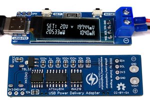
The USB A connector gets its power from the two 4mm banana jacks - one black and one red, in order to denote polarity. This allows the device under test to be powered from an external lab power supply with just 2 standard banana to cables, like the once showed in the photo.

PCB Description

The layout is equally simple. In order to route the USB traces at 90ohms impedance, the JLC7628 stack up was used. The traces were routed with a spacing of 0.127mm and width 0.2mm, as per JLC's impedance calculator. Layers 2 and 3 are ground plains.
Yes, this board work just fine as a 2 layer board, since the traces are short, but 4 layer boars are cheap and i wanted to get the required 90ohms impedance, as specified in the USB2.0 standard.
I designed the silk screen to be as descriptive as possible for anyone using the board. It describes both the power path and the data path.


 Stefan Wagner
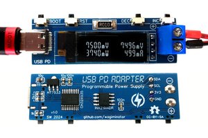
 Kn/vD
Kn/vD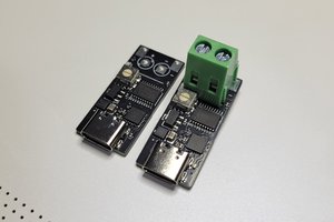
 CentyLab
Hello Nikola,
What value is used for C1 and C2?