Overview
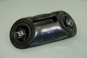
I have built a relatively small USB-C powered capacitive discharge spot welder, which can be used to build battery packs for various devices and avoid throwing old devices out just because it's not possible to buy an original battery anymore. I tried to design this spot welder in a bit different way than other spot welders.
The challenge
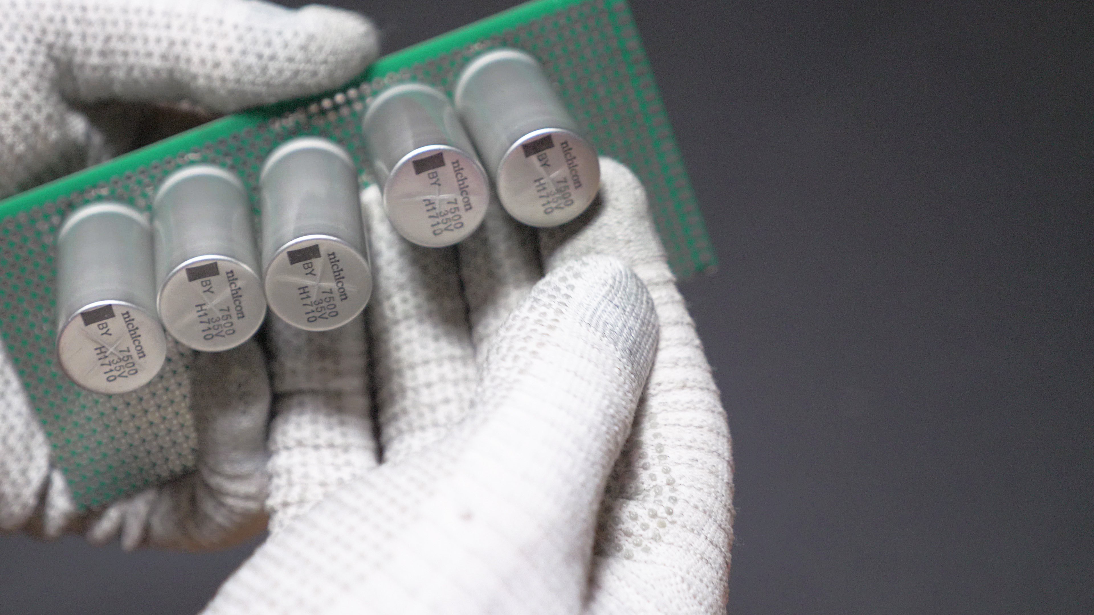
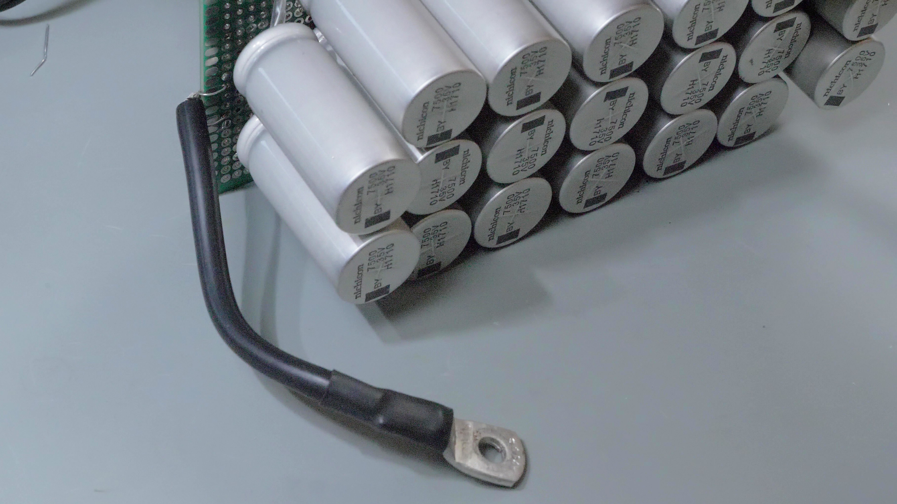
1. I wanted this spot welder to be relatively safe to use and safe to store. Other spot welders often use car batteries, microwave oven transformers, high-current li-po battery packs or supercapacitors as power source. All of these things seemed to be very powerful and somehow scary to me, so I decided to use an capacitor bank made of regular electrolytic capacitors. These capacitors can store enough energy to make a spot weld, but not much more than that, and there is less of an risk of something bad happening in case of a short circuit.
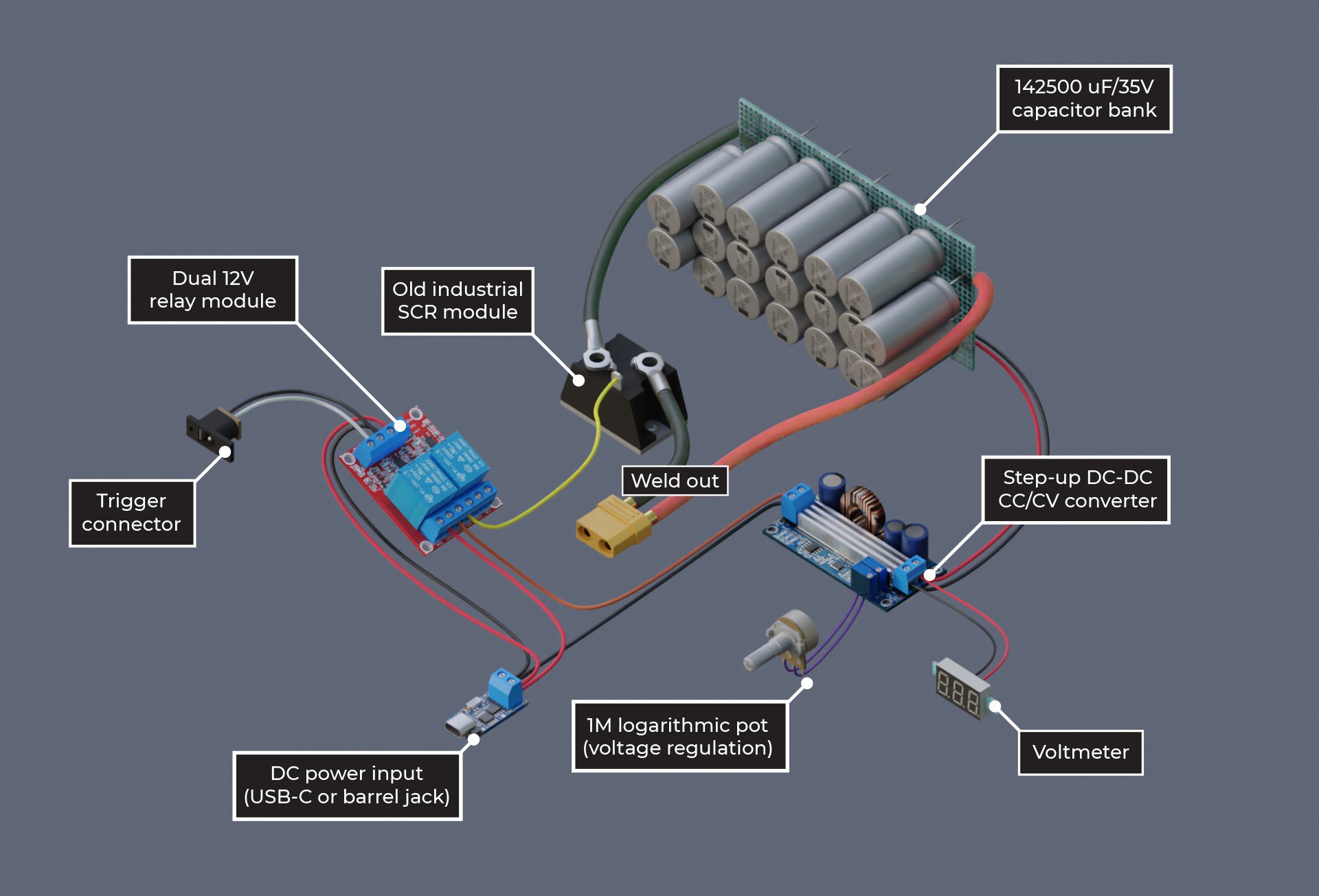
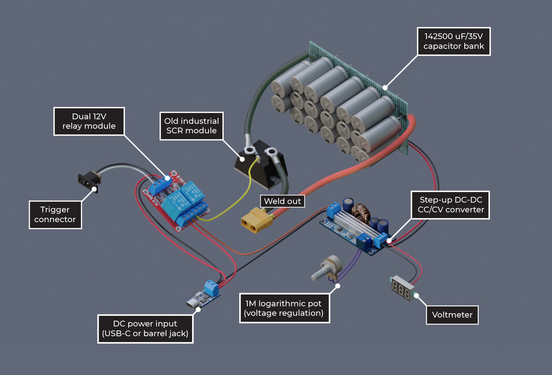
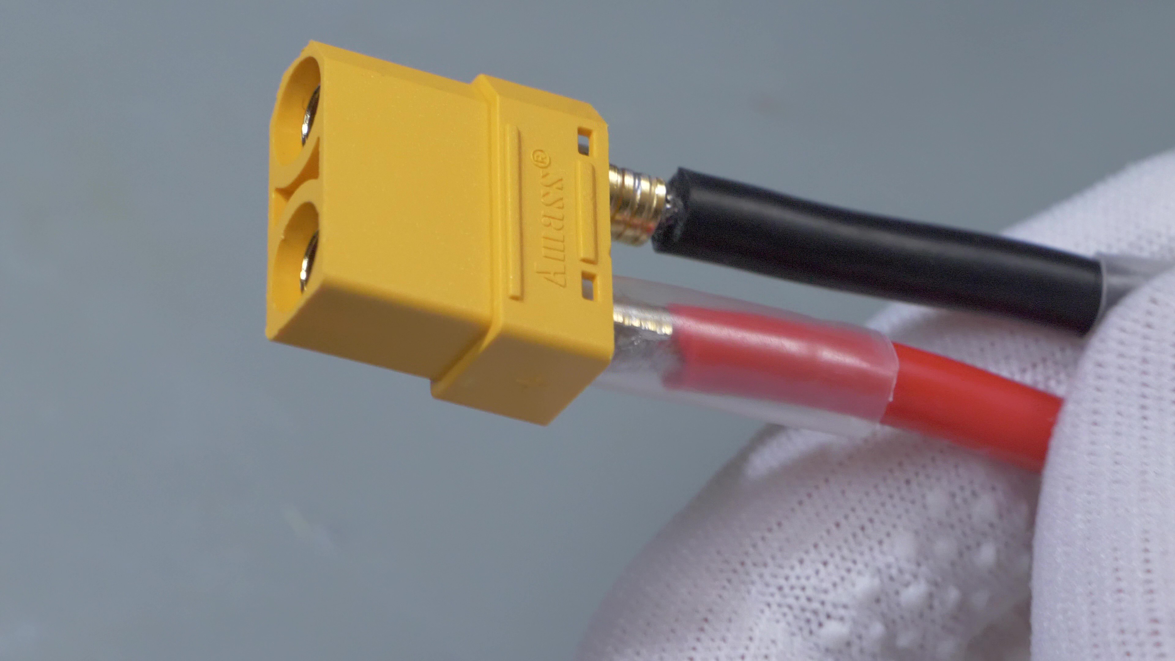
2. I wanted this device to be fairly easy to build and avoid the need to use custom PCB. Therefore I created it in a modular manned, and chose to use an old industrial SCR module to switch the welding current, off-the-shelf relay module with slight modifications to time the pulse triggering and charging right, step-up converter module with potentiometer added to control the pulse energy and USB-C PD trigger module (optional) to allow powering the welder with powerbanks.
3. No microcontrollers: a button, a panel voltmeter, a potentiometer and a relay module with timing capacitors should be enough. Might help a bit in times of silicon shortage.
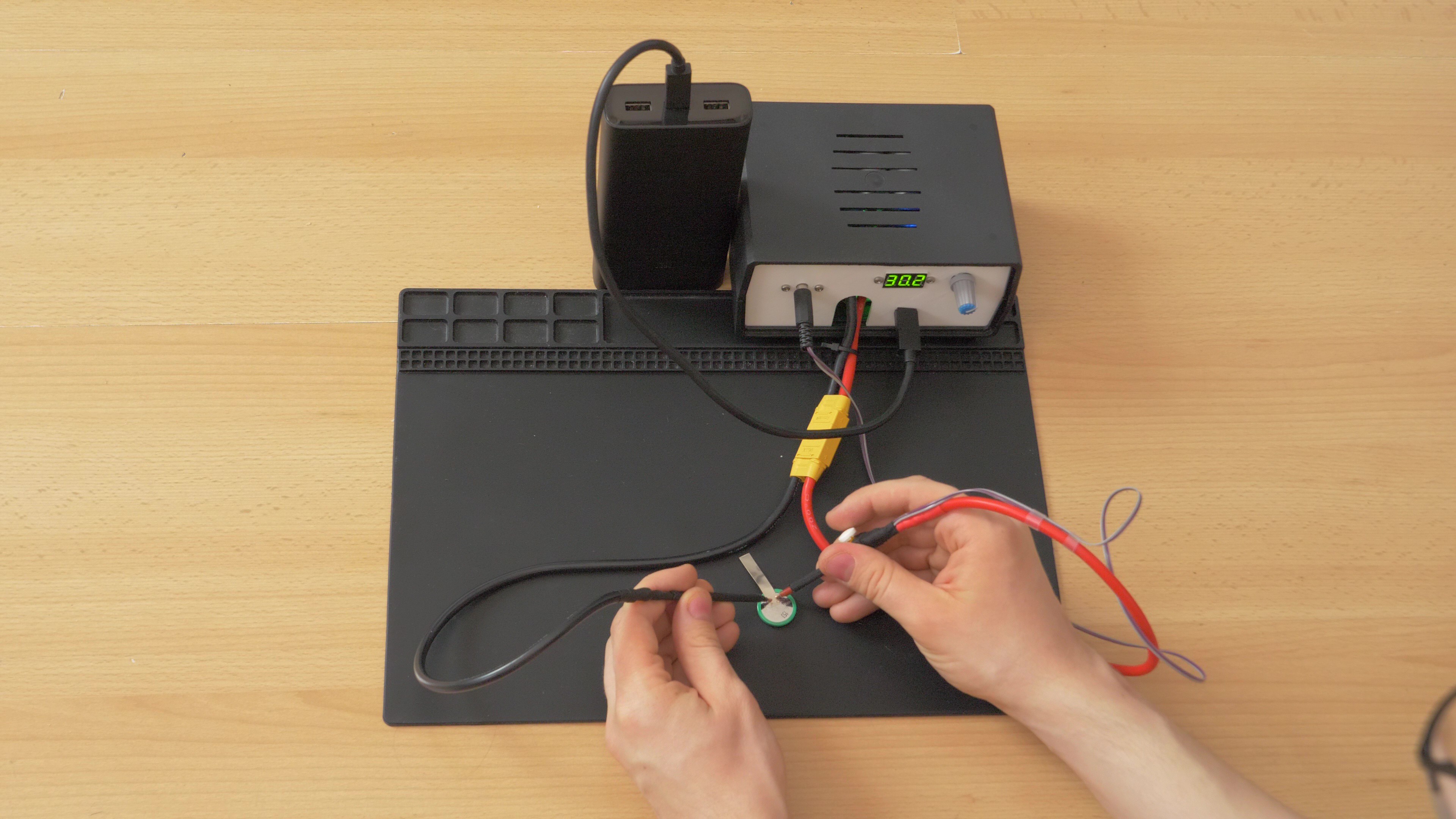
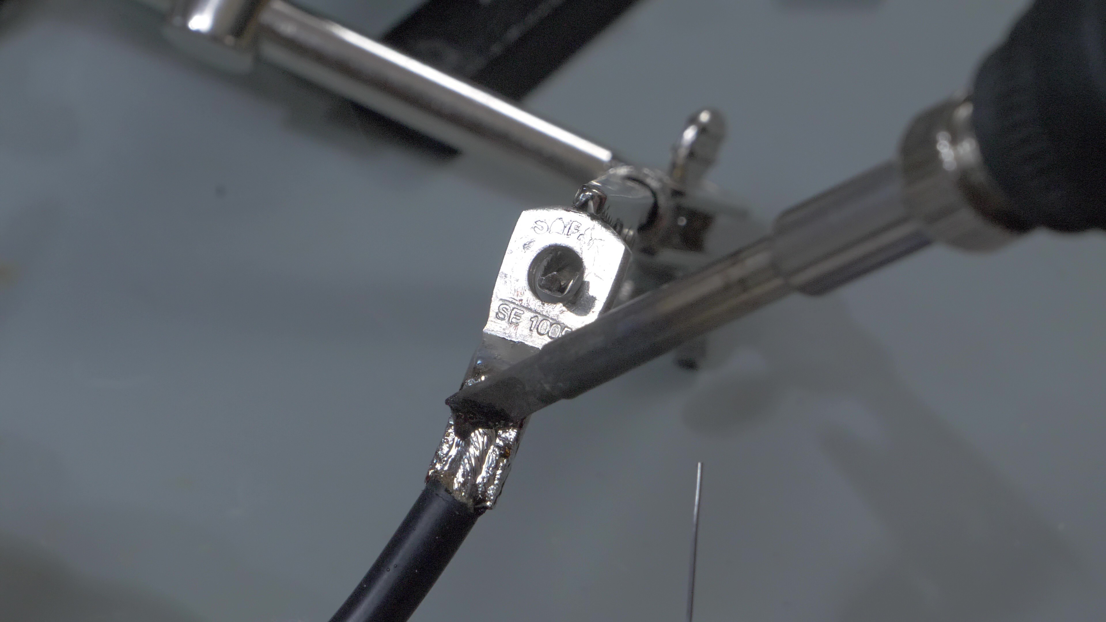
4. I wanted it to be compact. I made a custom 3D printed panel and packed everything tightly, but in a rather tidy manner into a plastic case. I didn't want to use a bulky footswitch, therefore the triggering button is placed right on the welding electrode, easily pressed with a finger.
What to do next
At the current stage, this spot welder uses mostly off-the-shelf modules and does not use a custom PCB. This is exactly what I aimed for and probably the most cost effective way to build this device. However, an ability to build it from scratch would also be nice, because it would allow a greater degree of customization of the device, and possibly making it even smaller. Therefore I am in the process of creating a schematic of this spot welder using discrete components to replace the relay module and step-up converter board.
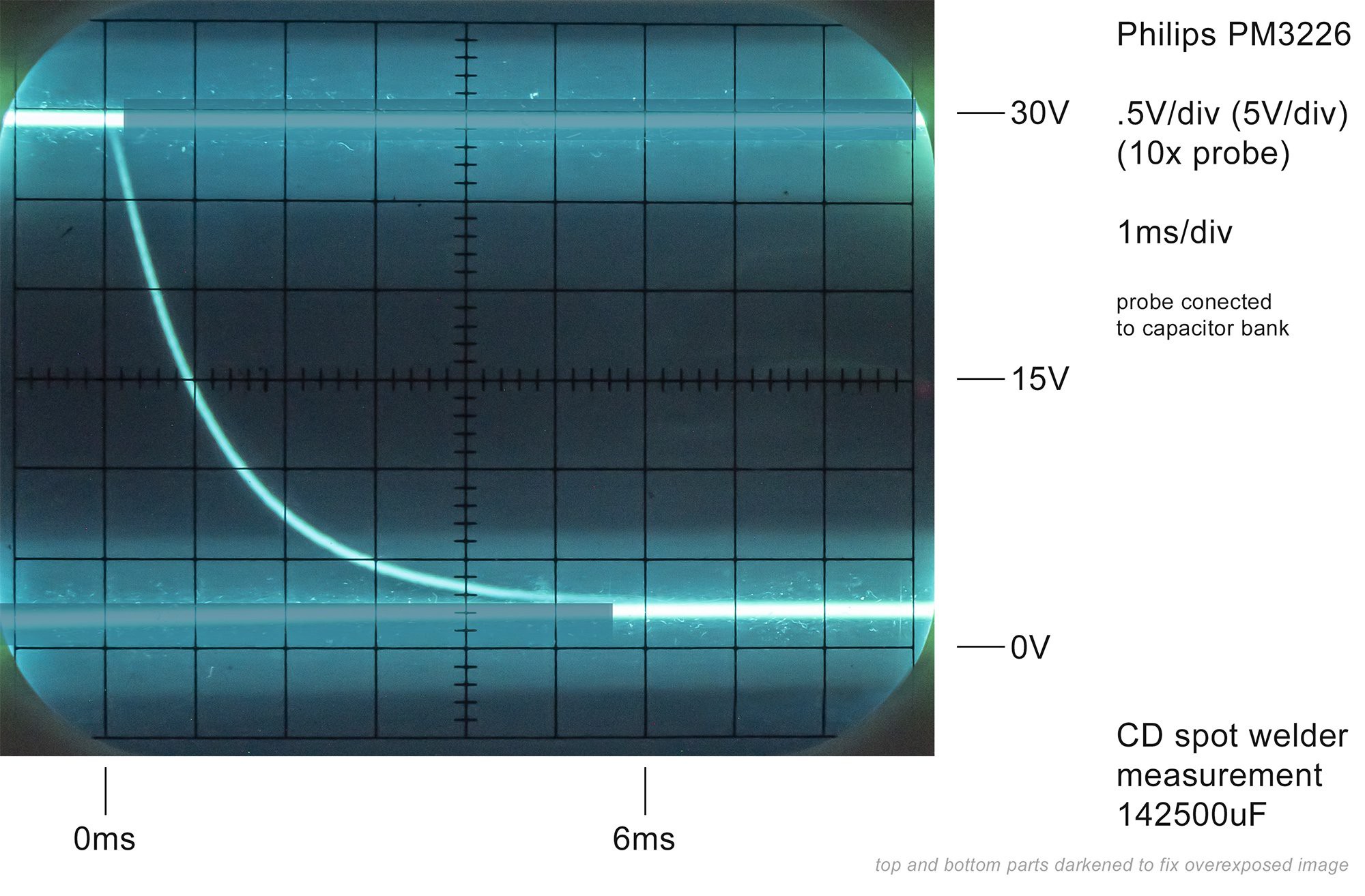
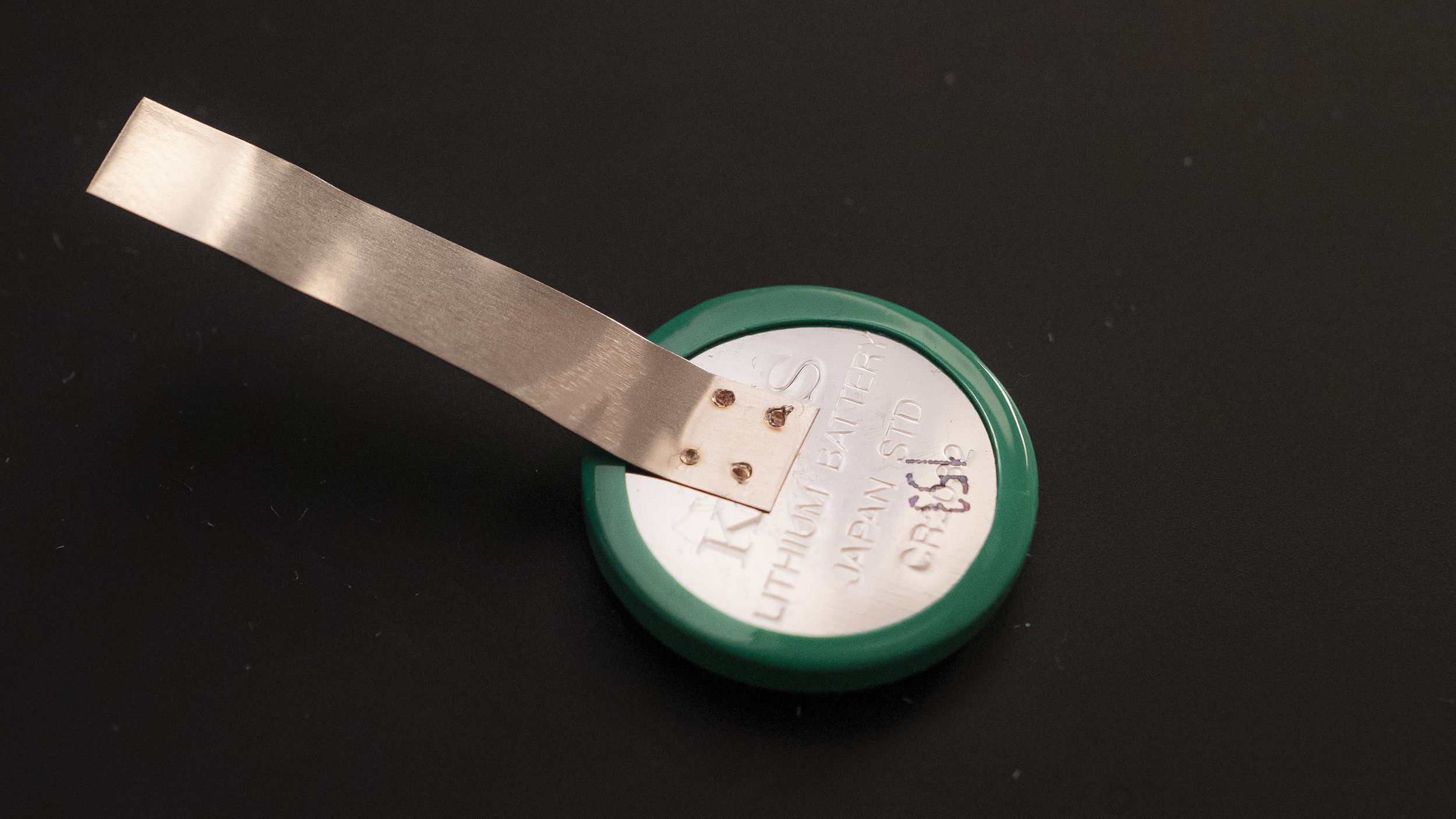
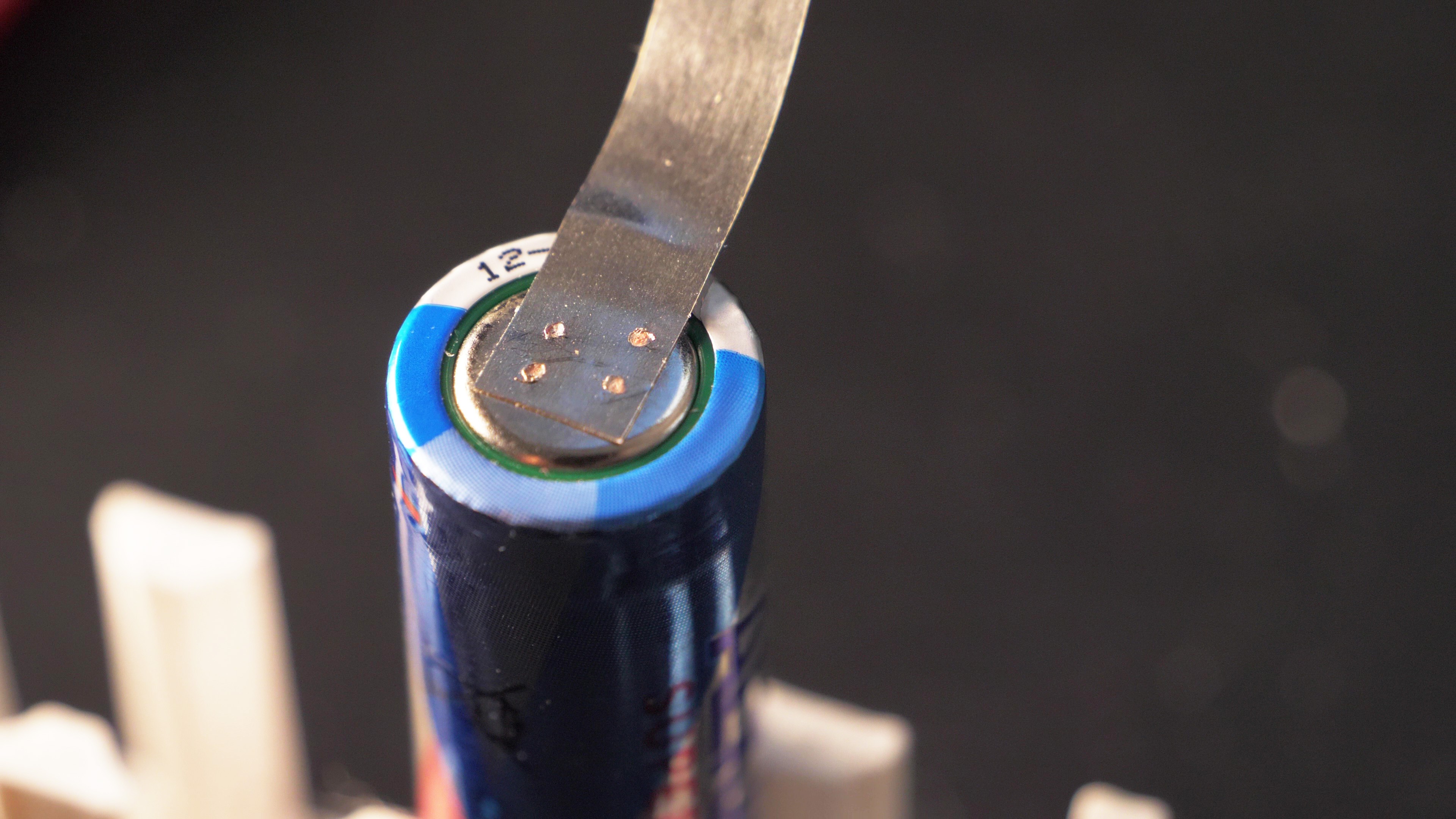
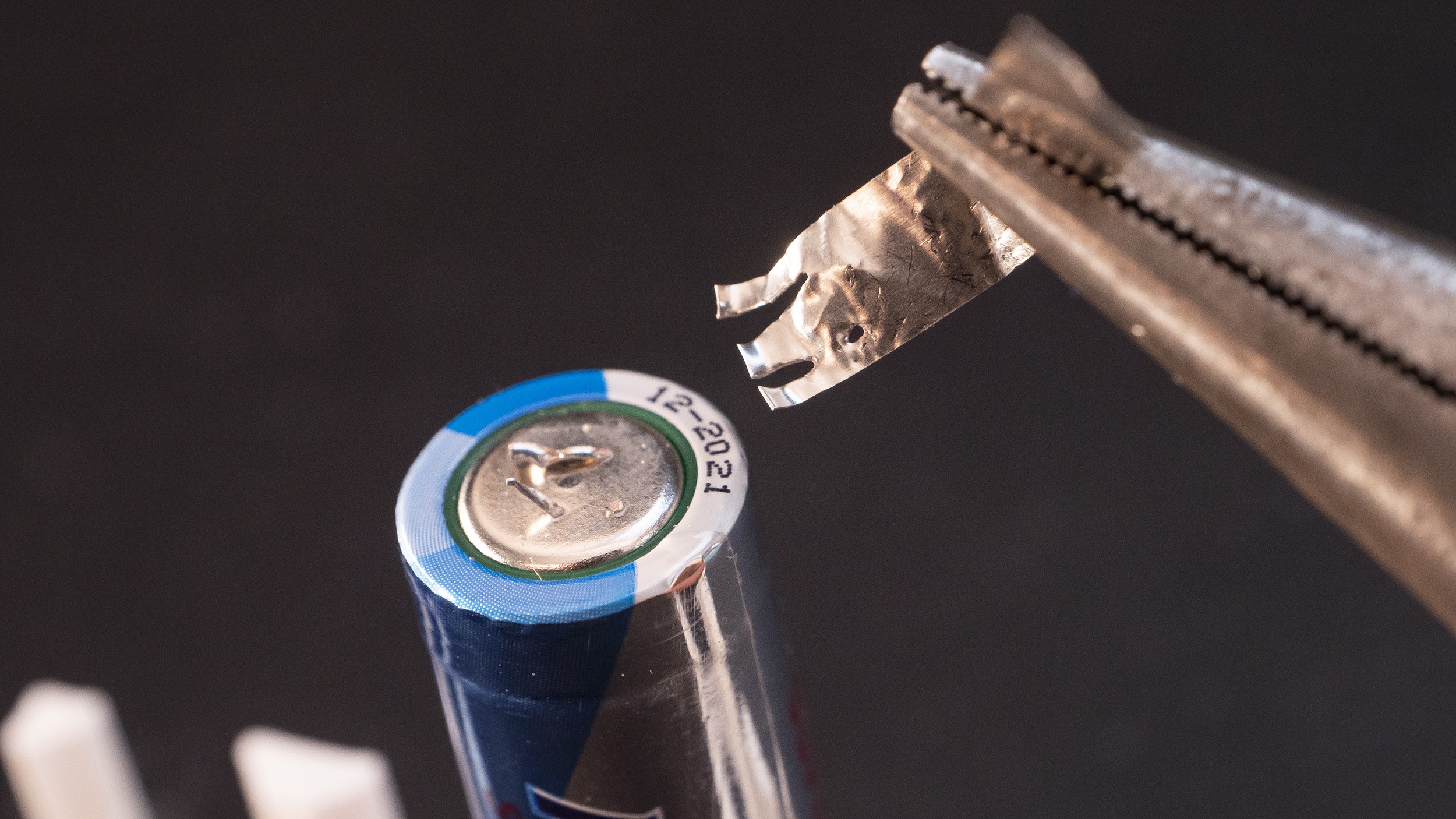
Initial tests already have shown that this welder is capable of creating usable welds of nickel stripes, but I need to do more tests with various voltages and strips of different thickness.
Currently this spot welder uses automotive grade Nichicon capacitors. It would be a good idea to check the feasibility of using cheaper capacitors, and test if it's better to use higher voltage ratings, or higher capacity.


 Moritz Walter
 mircemk
 Frédéric Druppel
 Simon Merrett
Using a 370000uF capacitor bank (37 cheap, unbranded Chinese 35V 10000uF aluminium electrolytic capacitors 18*35mm, low ESR) and the same 12v dual relay, DC to DC converter, timing capacitor and RC pulse control described in Adalbert's original project I am successfully spot welding .3mm pure nickel strips (with the capacitor bank charged to 30.7v), .2mm pure nickel strips (with the capacitor bank charged to 21v), and welding .15mm pure nickel strips with the capacitor bank charged to 15.8v; but the up-to 7kA pulse produced by the larger capacitor bank did cause the T90RIA120 thyristor to fail (probably because the max ITSM of the 90A thyristor was exceeded by ~ ×2, even though the pulse would have been ~1ms compared to the 10ms limit in the 90A thyristor specifications). The damage to the 90A thyristor caused it to be permanently switched on.
I replaced the damaged T90RIA120 thyristor with a stud thyristor (Semikron SKT300 series with an ITSM of ~11kA). It is bulky and therefore external to the 160 x 110 x 90mm plastic case into which I had squeezed the 37 x 10000uF capacitors, the original T90RIA120 thyristor and the other components, but it is effective. The stud thyristor is inserted inline with the negative probe cable, and the cathode cable is bolted to the same connector inside the case as the original T90RIA120 thyristor. The thyristor gate is triggered by the same 12v RC circuit described in the original project. The stud thyristor has further lowered the voltage required to spot weld (see my stats for welding .15mm nickel strips using the original 90A thyristor and 370000uF capacitance in my earlier comment). I suspect the discharge time using this larger thyristor has been reduced to <1ms (probably .00055ms), assuming the amperage needed to spot weld specific nickel strip thicknesses using Adalbert's design is much the same regardless of the size of the capacitor bank and capacitor bank voltage. I don't have an oscilloscope to confirm my theory.
To protect the DC to DC step up converter from unintended discharge from the capacitor bank I inserted a 40v 3A diode between the capacitor bank and the converter, notwithstanding the converter specifications include output reverse voltage protection, and the diode causes minor forward-direction voltage drop.
In conclusion, as Adalbert contemplated, I confirm it is feasible to use cheaper capacitors; and increasing capacitance by 250% enables spot welding of .3mm pure nickel strips at 30.7 volts, and thinner strips with significantly reduced voltage; however, increased capacitance has led to deviation from Adalbert's original imperatives of compactness and low cost; the heavy duty stud thyristor cost twice as much as the T90RIA120.