 Dave Collins
PCB Design is complete! wow that took a while.
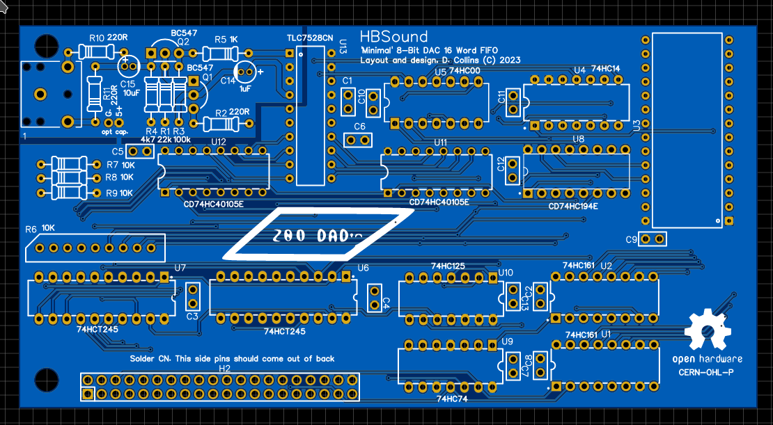
I thought I'd sit down and talk about the HBSound for a bit. If you don't know, HBSound is the DAC based sound card i've been developing for some months for my home brew computer, the HB6809. I haven't updated the Hackaday.IO site for a while and the reasons for this are varied but basically I am ready to share what I have for a few short falls at the end. I had a computer crash and had to re-establish a tool chain completely on my laptop. Its a better set up and I purchased a New old stock docking station to be able to un-dock my laptop and take it with me to work so I can update the project files on my lunch breaks. I didn't loose any important project files, most of this was in the cloud, but re-establishing a firm working set up was time consuming. I was planing on doing a video walk through of the control unit but as I've come down with a case of strep writing out my thoughts here may have to be good enough for a while.
First some caveats:
Every time I do a custom PCB design, I get feedback which I am very grateful for but here's a few things to keep in mind:
- Autodidact warning - I am self taught - this could be 100% wrong - but I did do testing on real hardware to determine its at least effectively working for my use-case.
- This is not a high speed design - it does not adhere to high speed design practices, it is meant to work at the maximum E value found in my computer which is 1.8432 MHz. I should mention Howard W. Johnson / Martin Graham's book on high speed digital design (It is very good if you are in to that sort of thing)
- This is a hobby, I do it for fun - I don't plan to mass produce or sell any of these things that I build and so the build quality is not always going to be what you would expect from a commercially provided, professionally designed product. Furthermore, I don't expect that I am the best source of information on the "right way to do something" -- you absolutely should take everything here with that grain of salt.
all of that in mind, I do from time to time take 'service in kind' sponsorships, every benefit I get from that is directly fed back into my projects and I greatly appreciate that support, as I don't think I would be able to do much of any of this with out it.
That out of the way here we go:
The control bit:
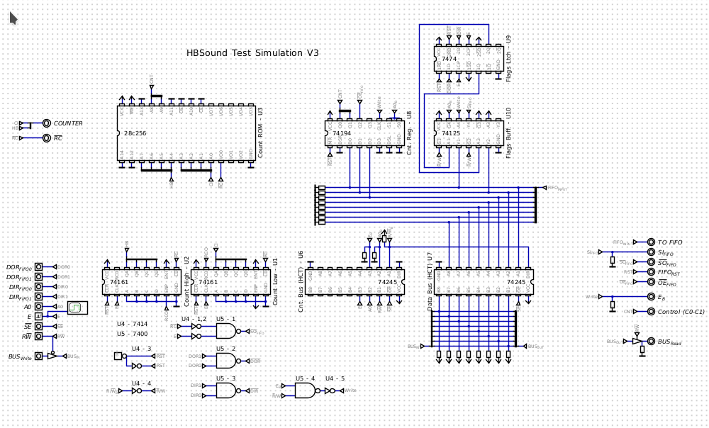
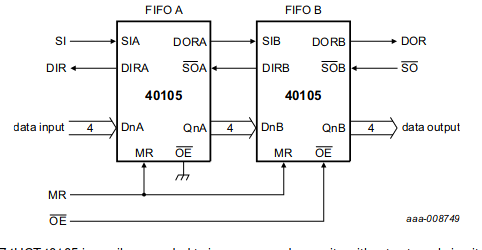
I spent a ton of time working on the control portion of the sound card. Several iterations of this design were assembled in H. Neemans Digital. I wound up going with this simplified design. I wanted to try to stick to discrete components that are mostly available still from digikey / Mouser - I could have most likely built the counter logic within a single or maybe to GAL's but for working with the parts I had on hand, and what I know I went with a Winbond W27E257 EEPROM as my only used / new old stock part. I had to use a 28c256 in the simulation but the actual part was the 12v eeprom. You can still get these in mass as pulls from 486 era PC motherboards on Amazon / Ebay and I have a ton -- I suspect many will also. The Fifo Selected is a standard CD74HC40105E, this allows the bit stream to be built in a buffer, which can give the programmer more time to do things while the slower DAC clock is shifting out the data. This technique was used in the famous (infamous? ) Disney Sound Source. Though, in that case a 555 timer was used to shift out the data at around 7kHz. The inevitable problem with this previous design is that the clock was inconsistent due to using a RC / 555 driven count (which would change the pitch off of a baseline), and many have argued that the similar COVOX sound adapter was a better solution as considerable better bit rates could be achieved even using a 8088 to control the timing.
Essentially the control piece does four things. First, it allows a set of flags from the 2 16 word FIFO's to be read by the user which allows the user to set the DAC bit rate between approx 7.2kHz and 32kHz in half step increments:
| System CLK | Sample Rt | Dec Count | HEX Count | BIN Count | OPCODE | HEX Address For Bit |
| 1843200 | 32000 | 56.6 | 38 | 0011 1000 | 00 | 38 |
| 16000 | 114.2 | 72 | 0111 0010 | 01 | 172 | |
| 8000 | 229.4 | E5 | 1110 0101 | 10 | 2E5 | |
| 7200 | 255 | FF | 1111 1111 | 11 | 3FF |
this is set by sending a write to the memory mapped address of the interface +1 using the above OP code chart. The 3rd bit on the same address enables and disables the output of the FIFO (effectively halting the audio). For this I used a CD74HC194E Universal shift register, wired as a standard 4 bit register. A large reason for this is its load on high control, made the select logic for the overall build much simpler. (also I have a ton, waste not want not)
Second, the control system passively creates a DAC clock, using the system clock a pair of counters and an effective OR gate to or the System clock (E), with the counter reset signal which is determined by counting through a dirt simple FSM stored in the EEPROM. The reason the DAC clock has to be OR'd with the system clock is so that the FIFO shift out only occurs on the falling edge of the system clock, as the status flags of the registers are clocked into the d-latches on the rising edge of E. This asures the flags do not get latched while a shift out operation is happening, as the flags on the specific fifo are dual purpose depending on when you look at them.
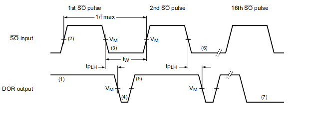
Marked Vm - during this period if both the SO and DOR are low, the resulting reading is that the FIFO is "BUSY", however if it is still low, after the SO returns high, the resulting reading is "EMPTY". This was done so that multiple parts could be stacked together:
Third the control unit has a 2 bit latch which stores the NAND'ed flags from the two FIFO registers. The Flags being NAND'ed provide /DIR and /DOR from the two FIFO's. This latch is pulsed by the system clock (the fastest time domain on the system) so when read it should represent the status of the registers based off the most recent SI or /SO. The register is mapped to the base address for the device, and reading from it will deliver these results to the system bus.
The fourth simply allows latching values into the on board FIFO. I tried to keep all of the write functionality very similar to the DSS, so that people familiar with this interface can program its operation or port code that they've already written to this interface simply.
FIFO / DAC & analog section:
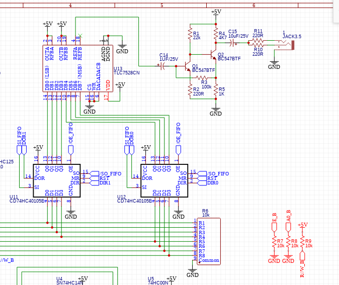
The FIFO is different, the DAC is a discrete one, but from this point the sound card is basically a Disney sound source. The DAC hooked up to use +5V for both the Digital & analog source. Its likely this will cause some distortion from digital switching but I've tried to minimize by separating the ground planes:
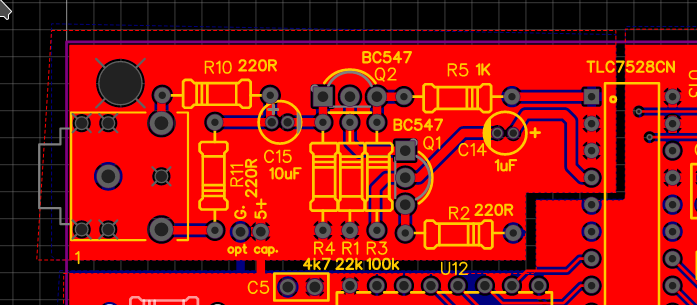
I did end up building a discrete pre-amp, instead of the weird powered speaker bit that the DSS uses. Even on a bread board this provides a fairly noiseless line output for a set of amplified speakers I feel most people will be using. I did wire both the left and right channels on the line out to the single channel output I just used a simple divided resistor network. With a set of headphones hooked up the volume level seems comfortable to me. I put a few pads on the power and ground planes for the audio section to filter some of the noise but I don't think it will be needed. I kept all of the traces on one side to try to keep the planes as solid as possible (only in the audio section), this was mostly done for noise reduction end to end in the analog section. Obviously I will know more when i get the boards back from the manufacturer.
Thanks for those of you who stuck with me thus far. Today I will try to get all the project files updated. I am working with getting the boards for the initial prototype to the manufacture. There is a bit of a time crunch as we come up on lunar new year, which effects getting boards back quickly. If you come back later this afternoon (CST) they will possibly be up to date.
Any questions or comments feel free to let me know what you think below or on Facebook. Thank you!
Discussions
Become a Hackaday.io Member
Create an account to leave a comment. Already have an account? Log In.