0%
0%
 Scott
ScottBecome a Hackaday.io member
Already have an account? Log in.
Just one more thing
To make the experience fit your profile, pick a username and tell us what interests you.
Pick an awesome username
hackaday.io/
Your profile's URL: hackaday.io/username. Max 25 alphanumeric characters.
Pick a few interests
Projects that share your interests
People that share your interests
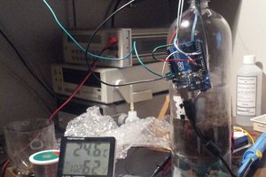
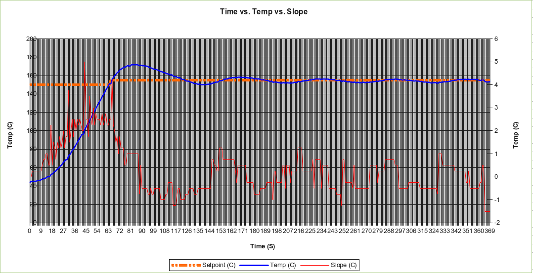 Tuning the “soak” stage


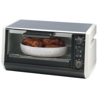 BLACK & DECKER Model TRO355
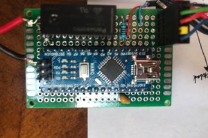
 Various PID Controllers
 TECHFX Reflow Controller


 W5FCX
W5FCX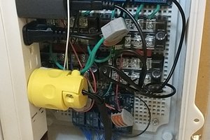
 Jonathan
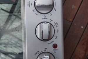
 Darren Blaxcell, aka Pork
Reflow-oven controller PID and performance tuning - https://smdreflowoven.wordpress.com/2016/12/06/reflow-oven-controller-pid-and-performance-tuning/