Introduction and direction
Introduction video describes an approach that is different from the current project:
- Active transmitter is a 1D array, used to focus "energy" or sound is a specific direction.
- Receiver is a simple mic that captures the echos from the direction of the transmitter.
- Transmitter is sweeping across the area of interest. The larger the area, the more "pings" is needed, the longer time it takes to generate a full image of the area of interest. This means that number of pings required to generate an image, limits the fps.
The current project uses a different approach:
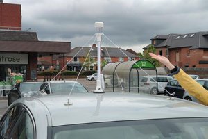
- Transmitter is either a loudspeaker or a ultrasonic 40kHz transmitter.
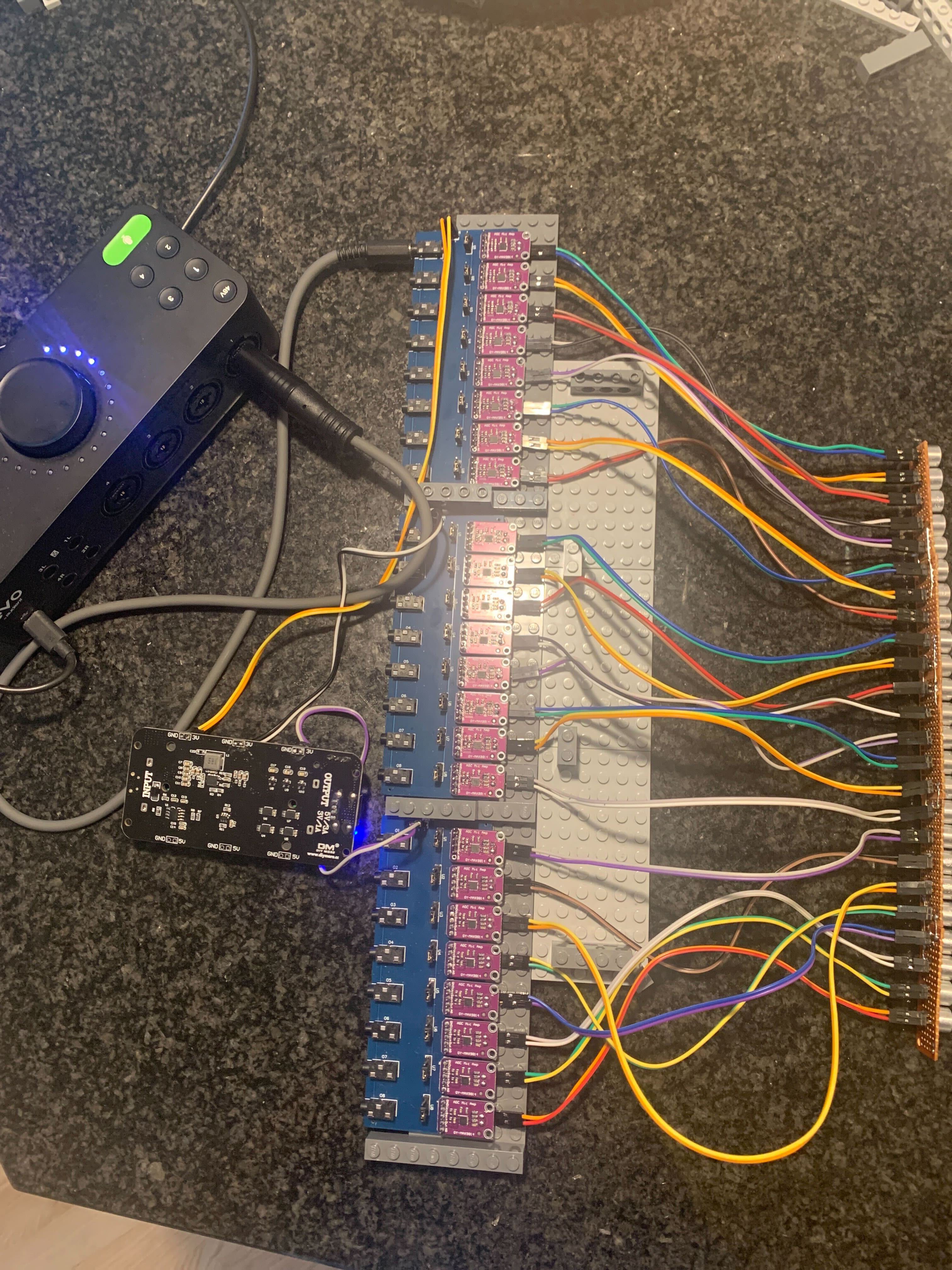
- Receiver is a 1D array, consisting of 8-24 elements. The larger array is, the more narrow beams, but also more processing time.
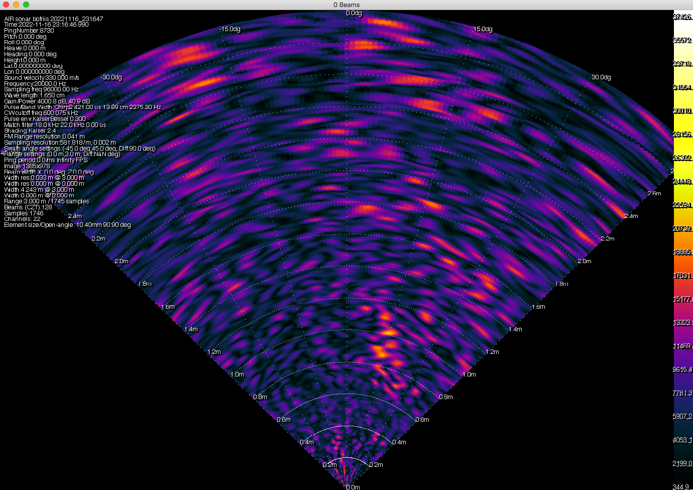
- Receiver is recording all channels, converts data in IQ, beamforms and shows the result. Processing is heavy, which is why I use the Nvidia GPU to do the heavy-lifting. By using the GPU, we can achieve FPS around 10, meaning near realtime imaging.
- Transmitter can be replaced with an active array. If placed perpendicular to the receiver array, it will allow for capturing data in 3D. Either via sweeping or via multi pings combined. This is done by constructing the FM sweeps (pings) with different frequencies and using match-filtering to separate the pings in the resulting echos. Computational load will increase by the number of transmitter beams.
Phased array design
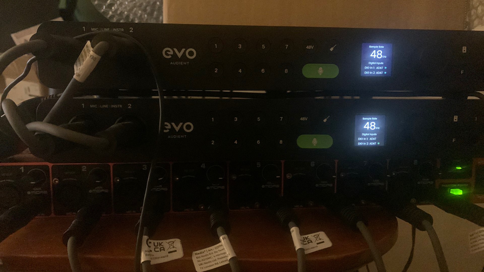
Hardware

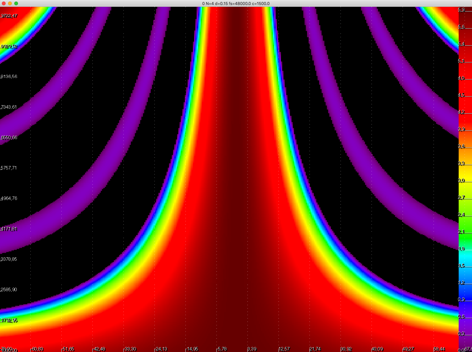
Pulse design

Signal processing

Beamforming tests


 Jianjia Ma
 Brett Walker
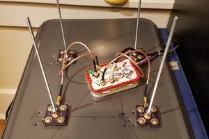
 Martin
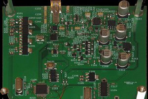
 MS-BOSS