joaquin dassori
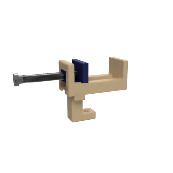
This 3D printed bench vise has a lot of exchangeable parts which can be modified by the user or replaced in case of a failure or breaking.
The printing parameters of this 3D printing are as follows:
- Standard resolution: 0.2mm
- Infill: 15% triangles
- Wall thickness: 0.8 mm
- Wall line count: 2
- Print speed: 50-60 mm/s
- Total printing time: 31h 51min
- Total weight: 258g
Parts:
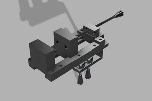
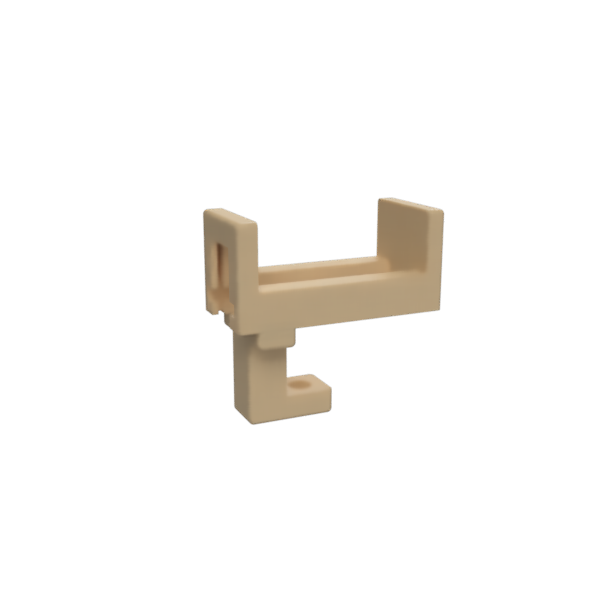
1) Body
Printing time: 12h 52min
Weight: 108g
2) Base
Printing time: 4h 48min
Weight: 44g
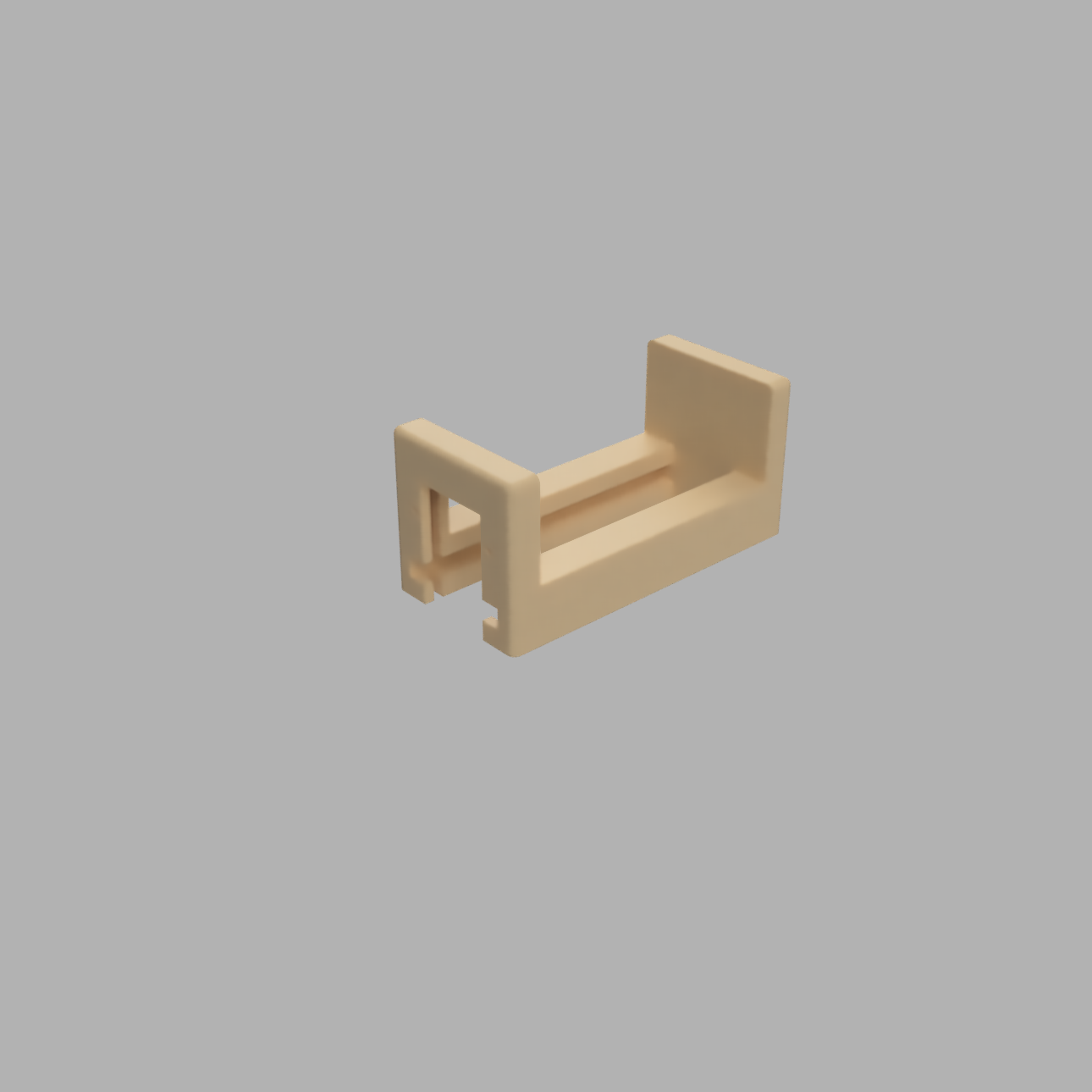
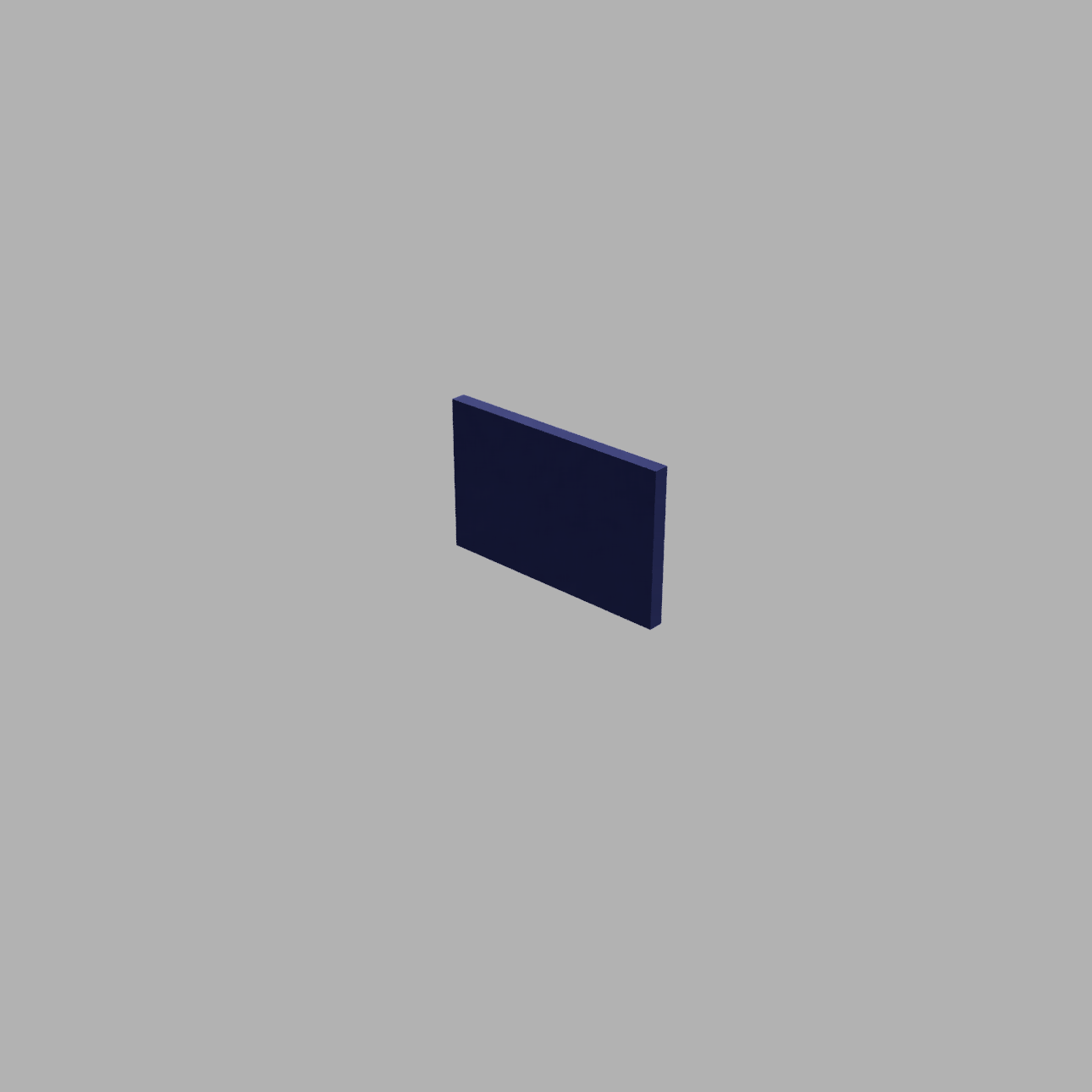
3) Wall
Printing time: 2h 12min
Weight: 21g
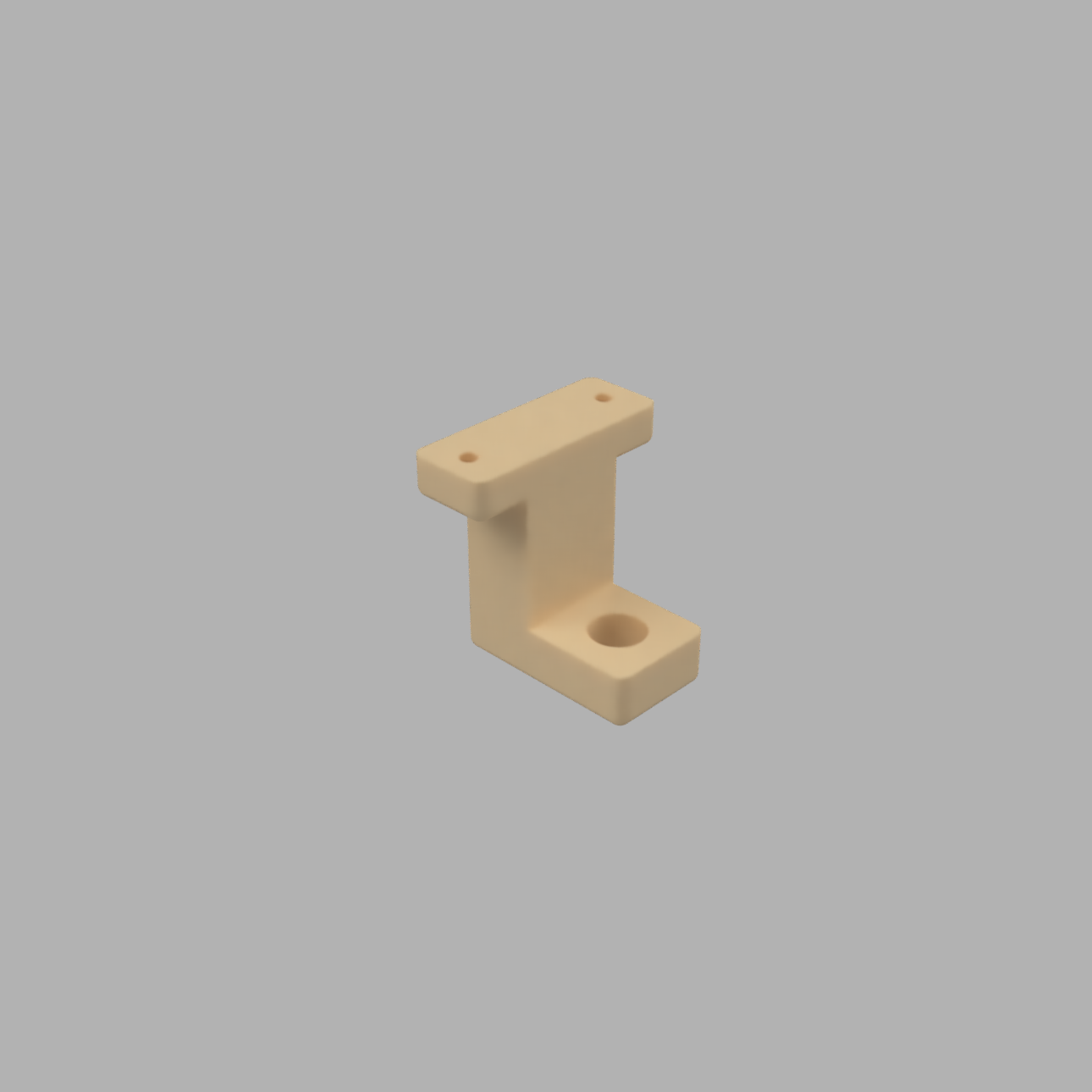
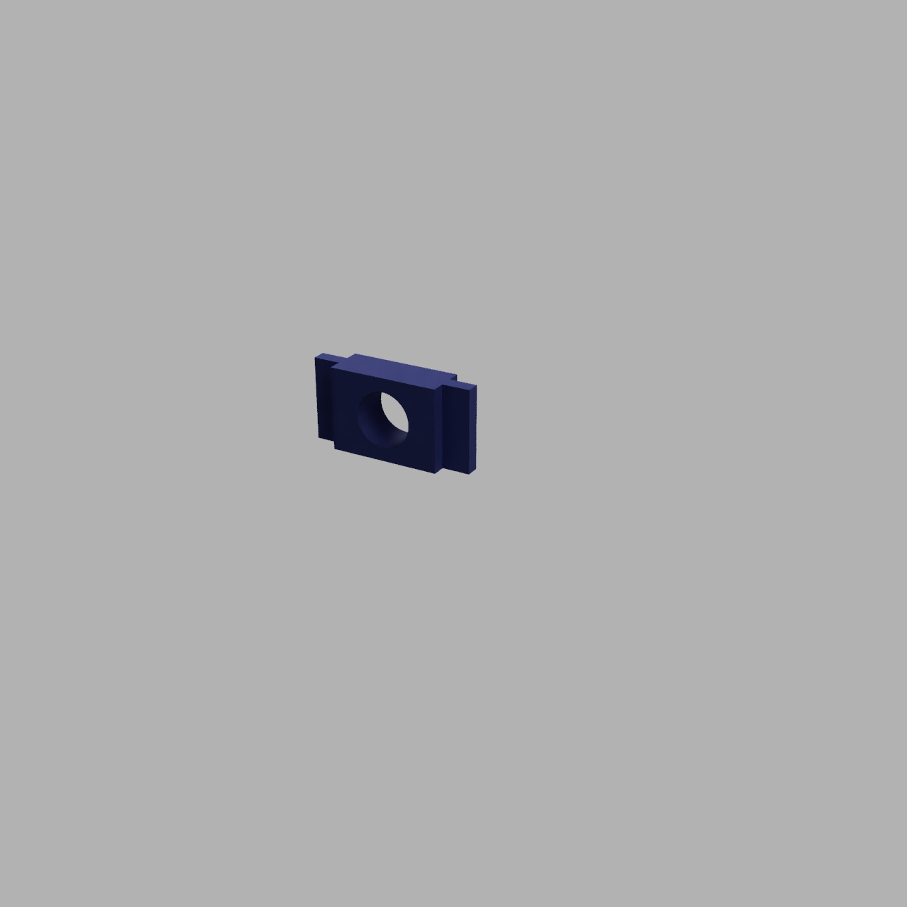
4) Face x2
Printing time: 2h 33min
Weight: 23g
5) Pin
Printing time: 1h 8min
Weight: 8g
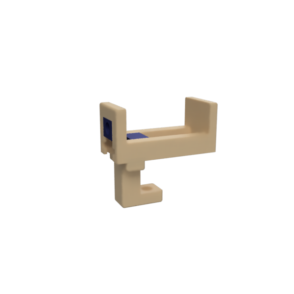
6) Slider
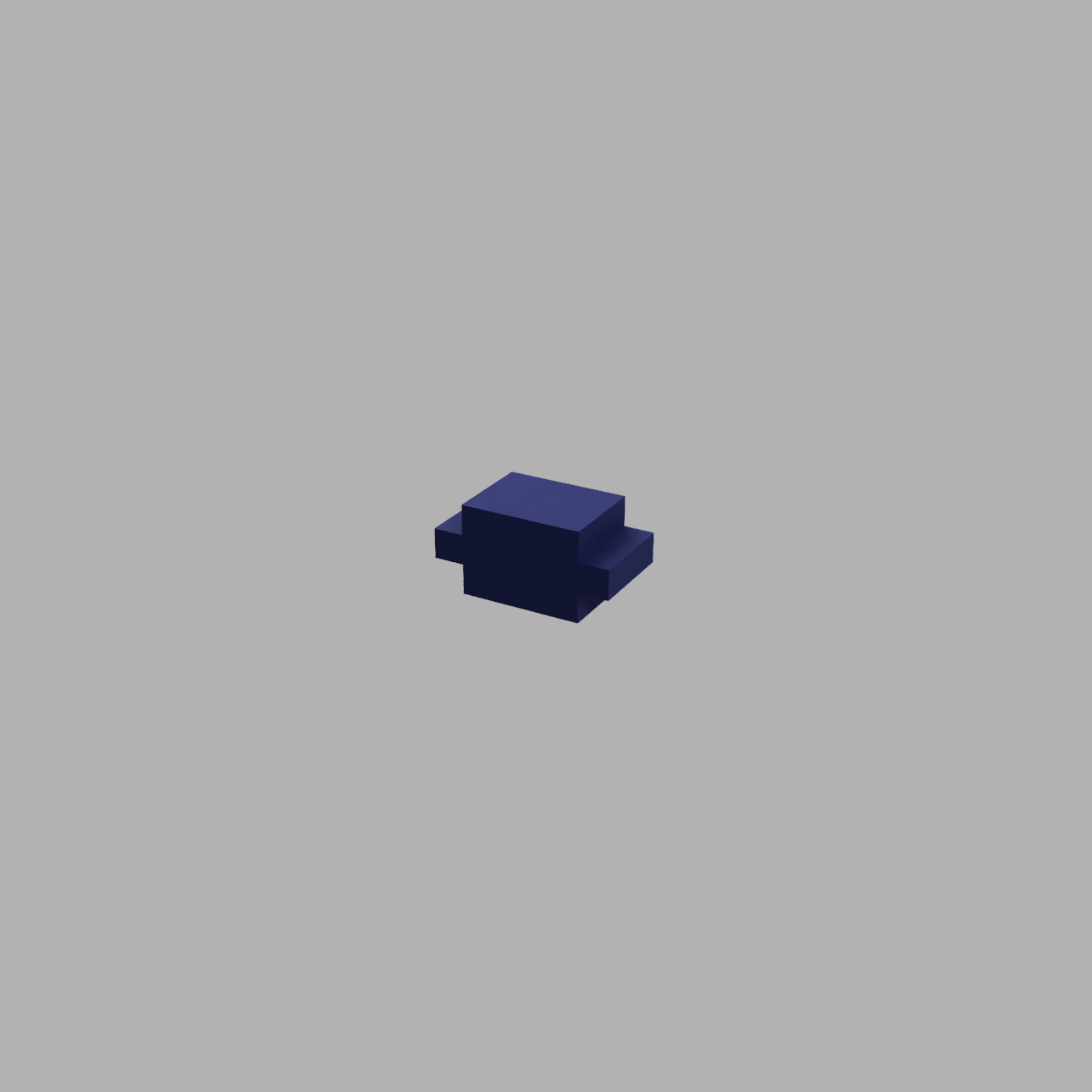
Printing time: 1h 35min
Weight: 15g
7) Screw 1
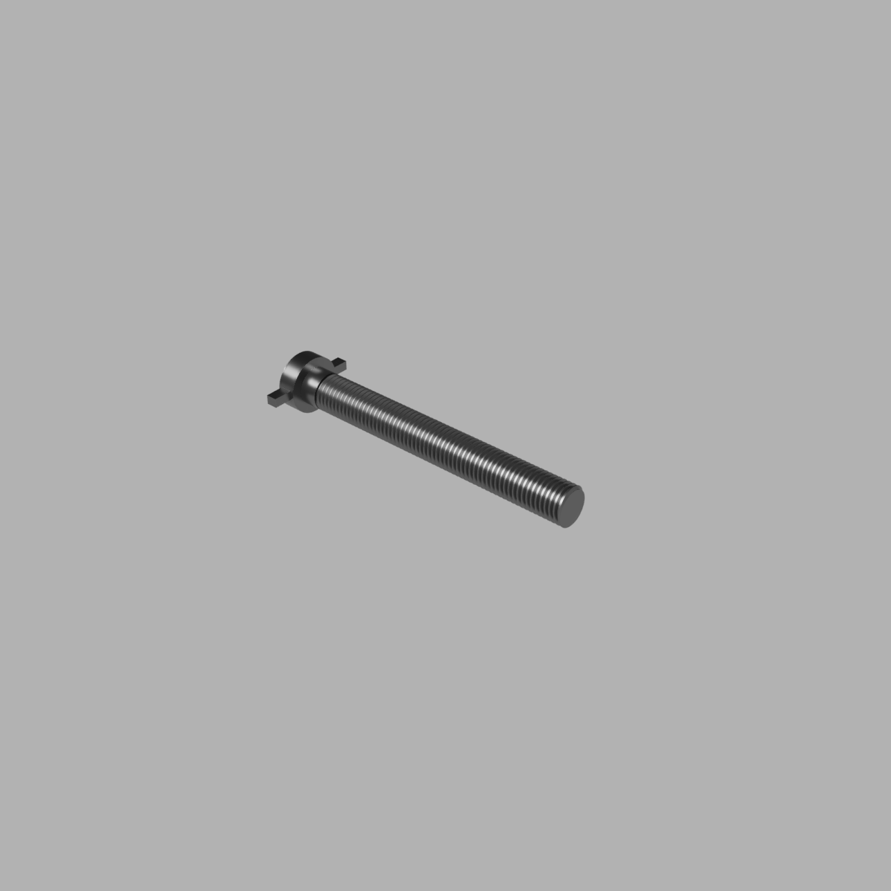
Printing time: 4h 12min
Weight: 24g
8) Screw 2
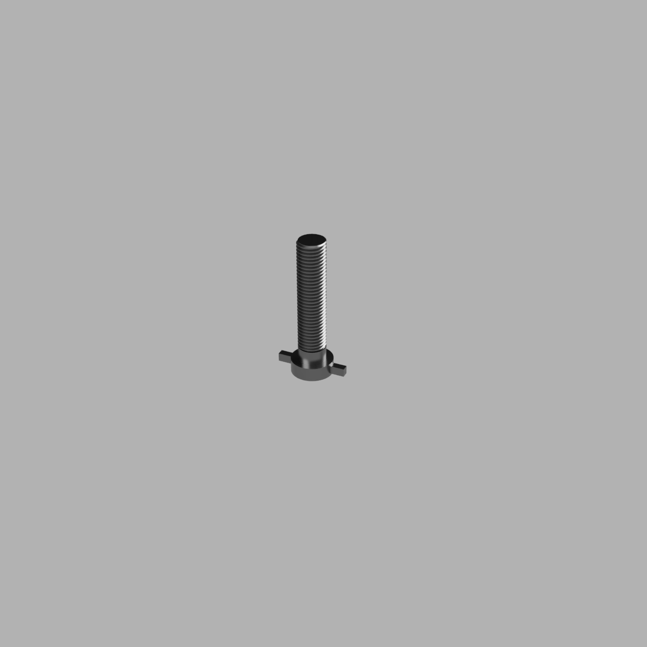
Printing time: 2h 31min
Weight: 15g

 Michał
 Bram
Bram
 Robert Mordzon